
Abstract
In this paper, a non-stationary enhanced swing angle suppression control strategy is proposed to address the issue of excessive swinging angles during the transportation process of a three-dimensional overhead crane. Firstly, in response to the substantial non-stationary initial swing angle resulting from the abrupt increase in driving force during the startup of the overhead crane, we have devised a time-varying damping resistance model. This model is specifically designed to curtail the rapid force surge, subsequently diminishing the swing angle of the payload. Secondly, during the transport phase of the overhead crane, we have established an augmented coupling signal between the displacement tracking error and the payload swing angle tracking error. Drawing upon the principles of energy dissipation, we have devised a nonlinear sway controller. Next, the closed-loop stability of the control system is validated through the use of Lyapunov’s method and the LaSalle invariance principle. Finally, the proposed control strategy’s effectiveness has been substantiated through simulation analysis and physical experiments. This approach not only proves capable of effectively suppressing excessive payload swing angles during the transportation process of the overhead crane but also facilitates the rapid and precise positioning of the payload. This significantly enhances the efficiency of the overhead crane’s transport operations.
Keywords
Introduction
Overhead cranes are widely employed in various sectors of the national economy, including construction, logistics, and manufacturing, due to their ability to efficiently transport large and heavy cargo between two points.1–3 When the overhead crane starts, the payload exhibits non-stationary initial swinging. Throughout its operation, the crane also encounters a combination of self-inertia and external uncertainties, resulting in unpredictable nonlinear oscillations of the payload. However, there are no actuators for payload swing control, so the actions of actuators like trolley and bridge must eliminate them.4,5 It is clear that the overhead crane swing angle control system, an example of an underactuated control system, has substantially fewer actuators than degrees of freedom. It is challenging for standard control methods to produce adequate control outcomes for such systems in this underactuated system.6–8 To mitigate the swing of the payload in overhead cranes and facilitate automated, efficient, stable, fast, and safe cargo transport, designing effective swing suppression controllers presents a substantial challenge for underactuated swing control systems.9–11
In the past few decades, researchers both domestically and internationally have made significant progress in the study of underactuated swing suppression control methods for overhead cranes. Most of these studies have focused on two main directions: open-loop control12,13 and closed-loop control.1,14–18 In the realm of open-loop control, Maghsoudi 12 used a nonlinear model of a three-dimensional overhead crane and a particle swarm optimization algorithm to design a shaper that combines the best unit amplitude zero vibration shaper parameters and cable length relationship. This shaper successfully adapts to the changes in cable length and crane dynamics during lifting to reduce the sway. Wu and Xia 13 designed several motion trajectories using the optimal control method for the transportation process energy efficiency issue. By comparing these, they discovered the best motion trajectory for swing angle suppression while considering safety, logistical considerations, and time constraints. While these open-loop control systems have been successful in reducing payload swing in overhead cranes, they have limitations due to the lack of closed-loop feedback and control to counteract external disturbances, thus limiting their ability to eliminate swing amplitudes.
Recognizing the limitations of open-loop swing control systems, researchers and practitioners have shifted their focus to closed-loop control. Huang et al. 14 studied adaptive anti-sway control for underactuated overhead cranes, ensuring transient performance guarantees. They improved the applicability of feedback techniques in crane system control and ensured that position errors and swing angles converge to zero at a given exponential rate through variable transformation. Zhang et al. 15 used error tracking control methods to derive error tracking control laws for any initial payload swing angle, effectively suppressing swing oscillations caused by different initial swing angles, payload masses, desired positions, and external disturbances. To increase the overhead crane swing angle’s control performance, stability, and trajectory tracking efficacy, Bessa et al. 16 integrated fuzzy control with sliding mode control. To accomplish the exact placement of the trolley, proper lifting and lowering of the payload, and efficient suppression of payload swing. Li et al. 1 proposed a coupling-based swing suppression control method that achieved precise trolley positioning, accurate payload lifting and lowering, and effective suppression of payload swing. Zhang et al. 17 addressed the problem of reduced transportation efficiency due to initial swing angles. They proposed a swing suppression control strategy for overhead cranes based on an energy analysis method, reducing the impact of initial swing angles on control performance.
The previously proposed underactuated anti-swing control method is suitable for two-dimensional overhead cranes. However, in real-world transportation scenarios, the trolley and bridge often exhibit interdependence, giving rise to a three-dimensional dynamic model for the overhead crane. In this paper, dealing with the three-dimensional overhead crane’s dynamic model, which involves a larger state vector and stronger coupling, poses a higher level of difficulty in suppressing swing angles. Therefore, investigating nonlinear control models for the anti-swing of three-dimensional overhead cranes, especially under non-stationary conditions, presents a more challenging endeavor. Fang et al. 18 combining decoupling control and PD control, proposed a nonlinear controller to improve transient effects. Tuan et al. 19 addressing the strong coupling problem in the state variables of three-dimensional overhead cranes, introduced a control method that combines partial feedback linearization and sliding mode control to enhance robustness in payload suppression. Zhang et al. 20 designed a model-independent proportional-derivative sliding mode control method that achieves both trolley positioning and payload swing suppression in the presence of external disturbances, unmodeled dynamics, and parameter uncertainties. In the context of swing suppression control for three-dimensional overhead cranes, the aforementioned methods have played a role, but their control precision is still lower than that of energy-passive control methods, which are adept at addressing strong coupling issues. For three-dimensional underactuated overhead cranes, Wu and He 21 suggested an upgraded coupling control approach to guarantee that the payload swing amplitude is almost constant at various transport lengths. This method is based on energy rectification and passive control methods. To address the issue of the regulation control method’s longer transport distance leading to an increase in payload swing angle amplitude, Zhang et al. 22 proposed an enhanced coupling underactuated three-dimensional overhead crane model. This model also improved the robustness and transient performance of the controller. By adding a second damping component, Zhang et al. 23 suggested a passive-based partially saturated nonlinear controller for underactuated overhead cranes that could respond to variations in production and transport distances without changing the control gain. Wu et al. 24 have proposed an energy-coupled nonlinear control method for an underactuated three-dimensional overhead crane system to address the issue of payload swing caused by trolley acceleration. This method effectively suppresses payload swing and achieves precise positioning of both the trolley and bridge. Zhang et al. 23 addressed the issue of poor passivity in three-dimensional overhead cranes by proposing an energy-coupling control strategy to improve the system’s passivity. They achieved this by injecting damping through a closed-loop system, enhancing the system’s passivity and ensuring effective suppression of payload oscillations and robustness.
In response to the aforementioned challenges, this paper presents a three-dimensional overhead crane swing suppression control strategy that is effective in addressing the swing suppression problem during the non-stationary operations of the crane from the starting point to the end point.
Firstly, to tackle the non-stationary swing suppression problem of the overhead crane’s initial position, a time-varying damping resistance model based on the displacement and swing angle decay trajectory is designed. Secondly, for swing suppression during the transportation process of the overhead crane, an enhanced coupling signal is established that combines trolley displacement error with the integral term of swing angle amplitude. This signal is used to design an energy-passive swing suppression controller based on energy dissipation principles. Using Lyapunov’s method and LaSalle’s invariance principle, the stability of the controller is rigorously proven from a mathematical perspective. The proposed non-stationary enhanced swing suppression strategy for three-dimensional overhead cranes is thoroughly validated through simulations and experiments on the respective platforms.
In summary, the main contributions of this article are as follows:
Due to the increased payload swing resulting from the abrupt velocity change during the startup of the overhead crane, a time-varying damping resistance model is proposed based on the positional error signals of the trolley and bridge. This model effectively suppresses the magnitude of the driving force during the startup of the overhead crane, smoothes the velocity change curve, reduces the amplitude of payload oscillations, and ensures the smooth operation of the overhead crane.
An improved coupling signal for the trolley and bridge has been introduced by incorporating trigonometric and logarithmic functions. Based on this enhancement, the proposed energy-coupling controller can rapidly suppress the load swing throughout the entire transportation process, eliminating residual oscillations in the load.
The proposed control strategy exhibits notable robustness, demonstrating its capacity to sustain high performance even in the presence of varying system parameters.
The proposed control strategy greatly mitigates payload sway during the transportation process of the overhead crane, consequently lowering safety hazards.
The remainder of the paper is structured as follows: In Section 2, the dynamic model of the overhead crane system is presented. Anti-swing control strategies with non-stationary enhanced swing angle suppression is proposed in Section 3. A thorough theoretical analysis of the stability of the proposed controller is provided in Section 4. The simulation results are displayed to demonstrate the viability and efficiency of the suggested controller in Section 5. The paper’s conclusions are presented in Section 6.
Three-dimensional overhead crane dynamics model
A simplified model of the three-dimensional overhead crane is shown in Figure 1, and its dynamics are modeled using the Euler-Lagrange equations:
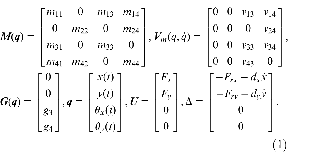
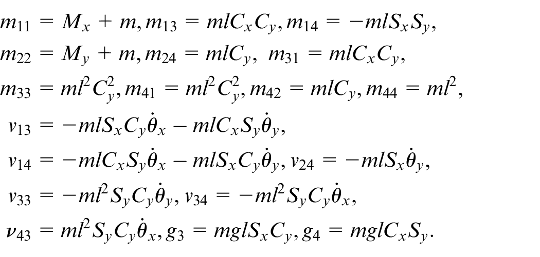
Where
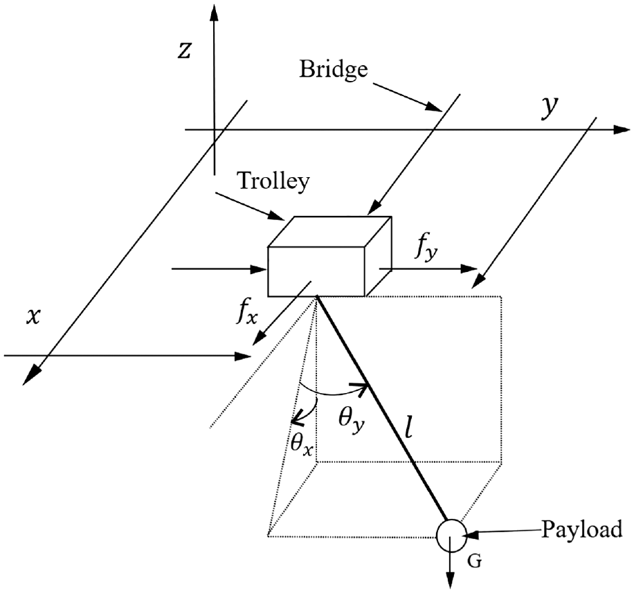
Simplified model of the three-dimensional overhead crane.
When the trolley and the bridge move along the track, the frictional forces they experience exhibit a non-linear relationship with velocity. The expressions for the non-linear frictional forces on the X and Y axis tracks are as follows:


Where
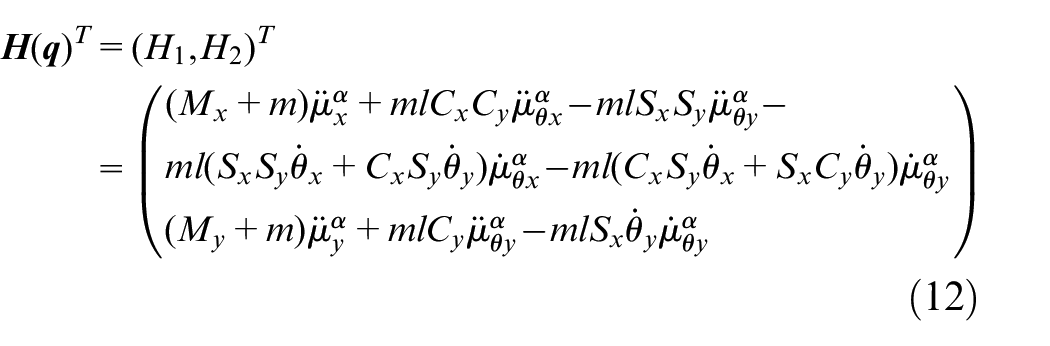
The following model may be used to determine a vector expression for the overall input to the system:
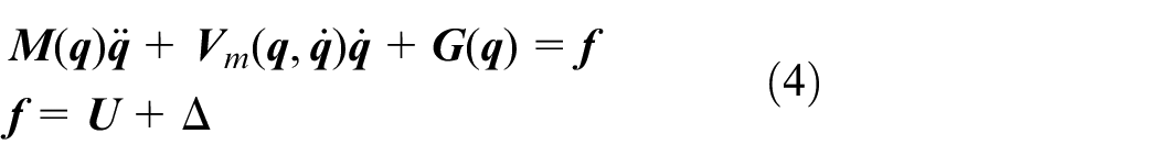
Where
Further division of the vector form of the total system inputs into actuated and underactuated variables gives:
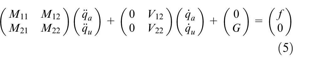
The three-dimensional overhead crane dynamics system exhibited in equations (1)–(5) has the following properties and assumptions:

Main results
In this section, addressing the issue of mitigating the angular displacement of the three-dimensional payload for an overhead crane, we first designed non-stationary angular displacement damping models for the trolley and the bridge crane, respectively. These models are aimed at reducing the non-stationary angular displacement during the initiation of the trolley and bridge crane. Subsequently, to enhance control over underactuated state variables via actuated state variables, we employed the energy dissipation principle. Specifically, we formulated distinct positioning error signals for both the trolley and bridge components. These signals were integrated into the overhead crane system enabling the construction of an energy-passive controller. This controller serves to decrease the three-dimensional angular displacement of the payload during the operation of the trolley and bridge crane. The control model of a three-dimensional overhead crane is shown in Figure 2:
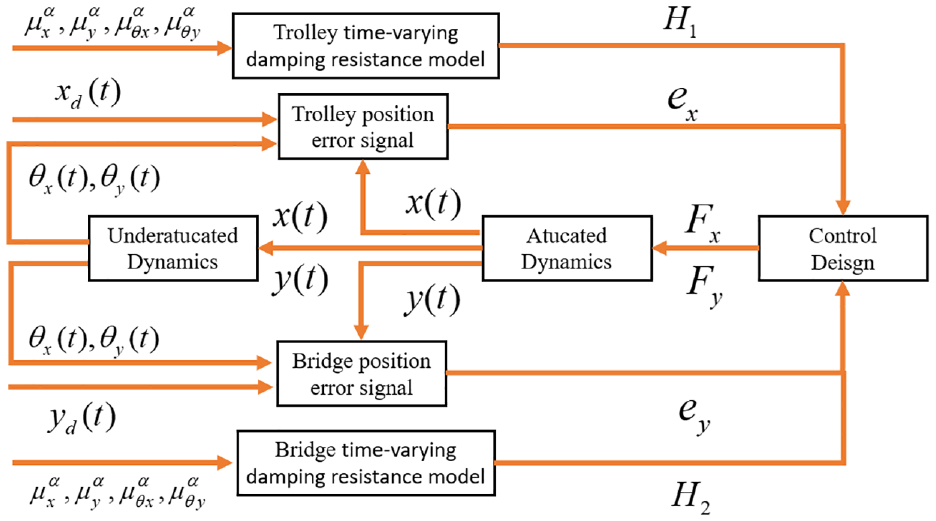
The control model of a three-dimensional overhead crane.
Time-varying damping resistance model design
When the overhead crane is initially started, sudden changes in the driving force can result in a significant initial swing angle for the payload, severely affecting the efficiency of equipment startup. To address this issue, displacement damping trajectories and swing angle damping trajectories can be designed in the X and Y axis directions. Based on these trajectories, an estimate of the payload swing angle decay can be planned. Using the Euler-Lagrange equation, the reverse driving force can be calculated to limit the magnitude of the initial swing angle.
The target position of the trolley in the direction of X axis is set as
In the three-dimensional space, combined with the exponential function decay speed and smooth curve characteristics, the design of suppression of the payload starting swing angle displacement decay trajectory and angular decay trajectory, as shown in equation (8).
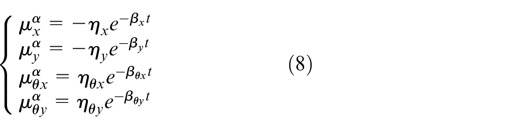
Where
Next, the position error tracking signal and the swing angle error tracking signal for the initial swing angle of the three-dimensional overhead crane are calculated using the displacement and angle designed in equation (8) as the tracking targets, combined with equation (7), as shown in the following equation.
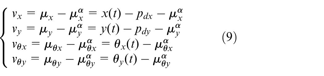
Where
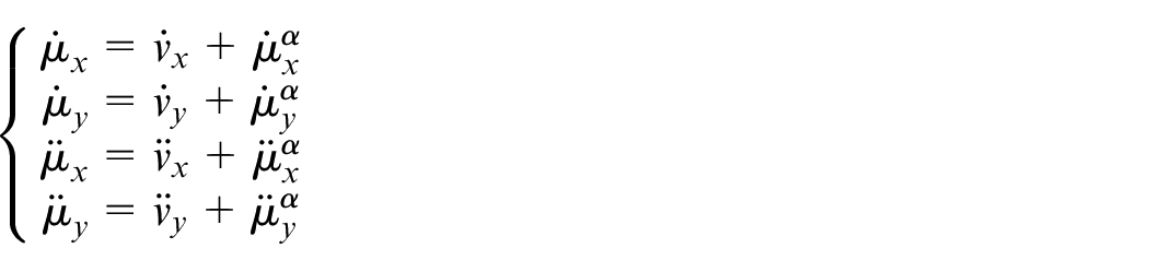
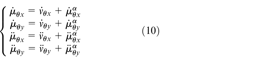
Variation of the above-generalized displacement and angle tracking error signal model and derivation of the transformed model gives:
Taking equation (10) into the Euler-Lagrange dynamics model of the three-dimensional overhead crane shown in equation (5), the collation gives:
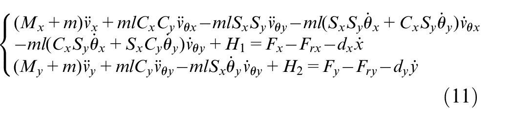
Where
The proposed time-varying damping resistance model can be adjusted by modifying its self-coefficients to control the magnitude of the resistance, thereby mitigating the rapid increase in driving force. This adjustment serves as a preventive measure against significant payload oscillations resulting from the abrupt increase in driving force, ultimately enhancing the suppression of payload swing angles.
Controller design
When the overhead crane is in operation, it is subjected to various factors and forms of interference in a three-dimensional environment, such as operating distance, system parameters, disturbances, and uncertainties, which significantly impact the stability and positioning accuracy of the overhead crane. To address this, an energy dissipation method can be employed to dissipate the energy associated with the disturbance-induced payload swing, thereby limiting the magnitude of the swing angle.
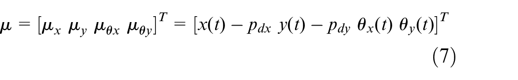
Regarding fixed rope lengths, the three-dimensional overhead crane swing angle control system with four directional degrees of freedom
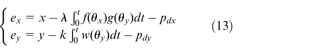
Derivation of the above position error signal yields:
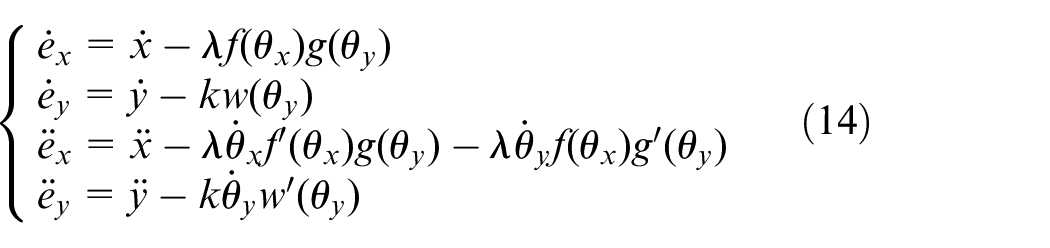
Where
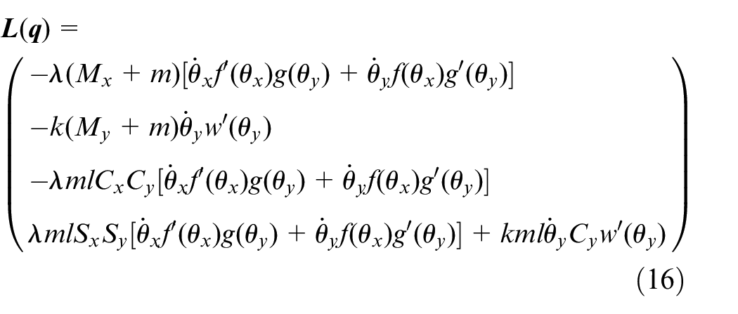
Combining equations (2), (12), and (14) yields the improved kinetic equation as shown below:

Where
The energy of a three-dimensional overhead crane system is composed of kinetic energy and potential energy, and its energy storage function is represented as follows:
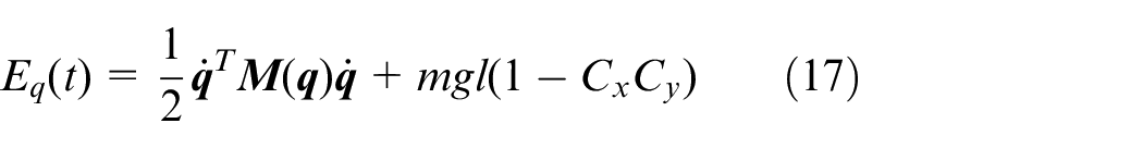
Using the error signal described by equation, equation (17) is rewritten as a new energy storage function:
Where
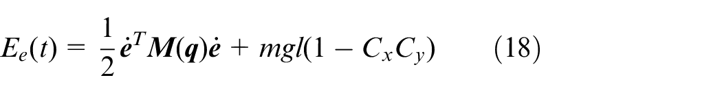
The effective payload swing angle is suppressed if the system’s kinetic energy decays to zero when the trolley and bridge transport the payload to the specified position. At this point, it is necessary to make the energy storage function
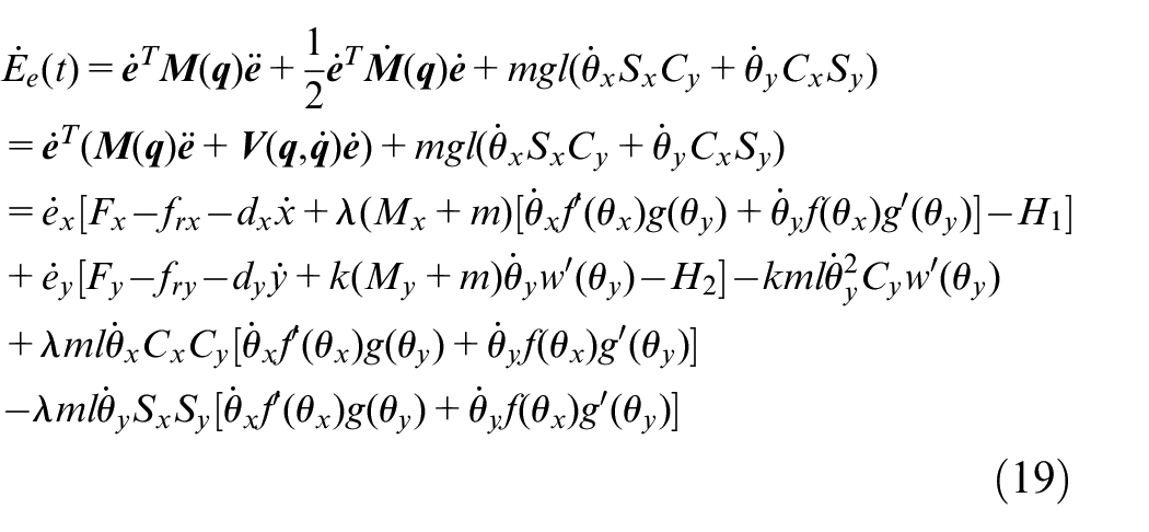
Using equation (19) as a basis and introducing the PD control term, the controller form for suppressing the three-dimensional swing angle is obtained as follows:
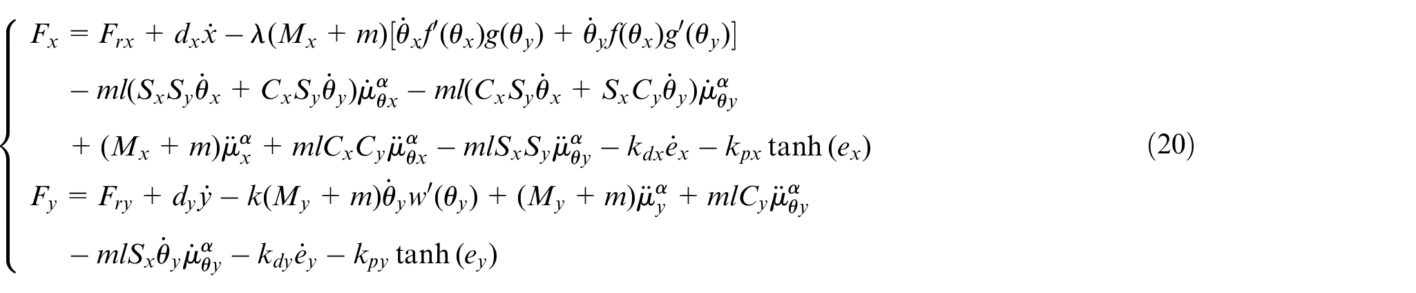
Where
To meet the requirements of the three-dimensional overhead crane system to transport the payload to the specified position, it is necessary to ensure that the last three terms of
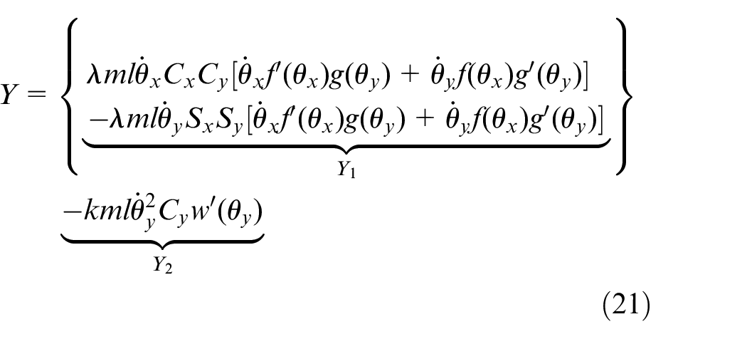
To ensure that
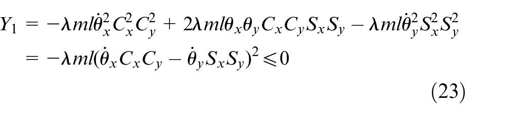
Select the functions to be designed

Taking equation (22) into
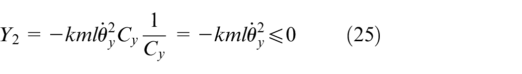
Similarly, Select the function to be designed

Taking equation (24) into
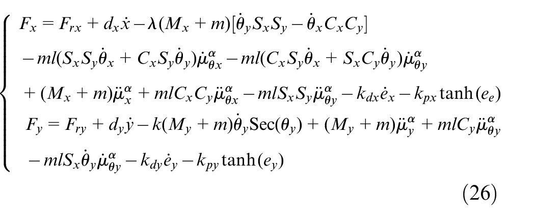
In summary, by combining equations (20), (22), and (24), the design of the proposed controller can be completed as shown below:
Stability analysis
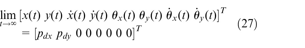
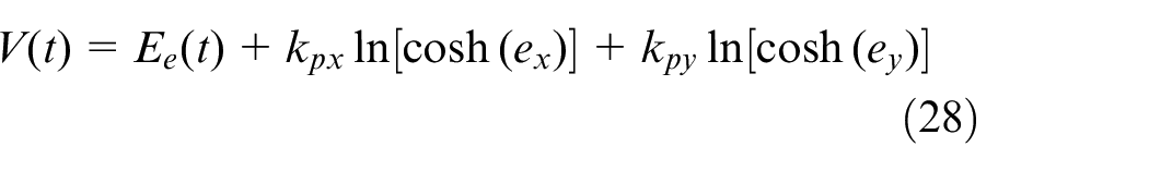
Where
In equation (28), the system energies
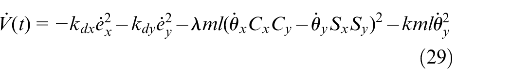
Based on equations (21), (23), and (25), it can be seen that when

From equations (18), (28)–(30), we have:

From equations (14), (18), (22), and (31), it follows that:

From equations (2), (3), and (32), it follows that:

From equations (13) and (32), it follows that:

From equations (1), (20), and (32)–(34), it follows that:

The asymptotic stability of an anti-swing control model for overhead cranes with non-stationary three-dimensional initial swing angles can be proved using the LaSalle invariance principle. Define the following set

Defines the maximum invariant set

Combining equation (14), it is obtained that:
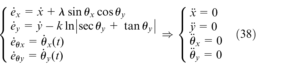
From equation (38), it follows that:

Where
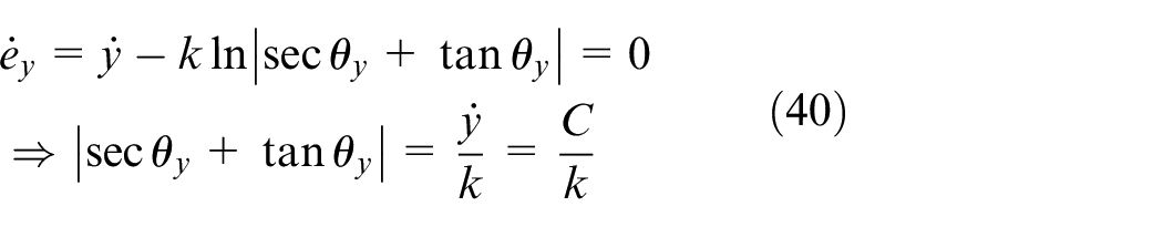
When
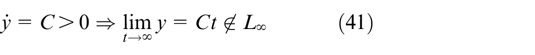
It follows that equation (41) is contrary to equation (34), and therefore, the above condition is only satisfied when

According to equations (14), (38), and (42), it can be seen that:

Similarly, from equations (38) and (43), it follows that:

From equations (2), (3), (42), and (44), it follows that:

Combining equations (11), (12), (15), (16), and (37)–(45), it follows that:

Combining equation (13) yields:

From equations (36)–(47), it follows that the equilibrium points of the system all contain the invariant set
Simulation analysis and physical verification
To verify the effect of the proposed control strategy on the pendulum angle in all aspects, experiments are then carried out for different cases of payload swing from both simulation and experimental perspectives, and the experimental effects are compared and analyzed.
Simulation analysis
To assess the effectiveness of the proposed control strategy, we conducted simulation validation in the Matlab/Simulink environment. The control strategy was subjected to verification using a variable step-size mode and the ode15s numerical solving method. Specifically, we start by determining the parameters for the proposed control strategy, the energy coupled controller, and the nonlinear tracking controller as mentioned in this paper. In the subsequent set of simulation experiments, we focus on comparative experiments. We compare the proposed control strategy with the energy coupled controller and the nonlinear tracking controller to analyze the superiority of the proposed control strategy. In the second set of experiments, the emphasis is on robustness testing. Following the principle of controlling a single variable, we systematically alter factors such as payload mass, cable length, desired position, and external disturbances to validate the advantages of the proposed control strategy in terms of robustness. In the third set of experiments, the focus is on testing the ability to suppress non-stationary three-dimensional initial swing angles. By introducing different initial payload swing angles, we verify the effectiveness of the proposed control strategy when dealing with initial payload swing angles.
Set the initial parameters of the three-dimensional overhead crane, as shown in Table 1:
Table of initial parameters of the three-dimensional overhead crane.
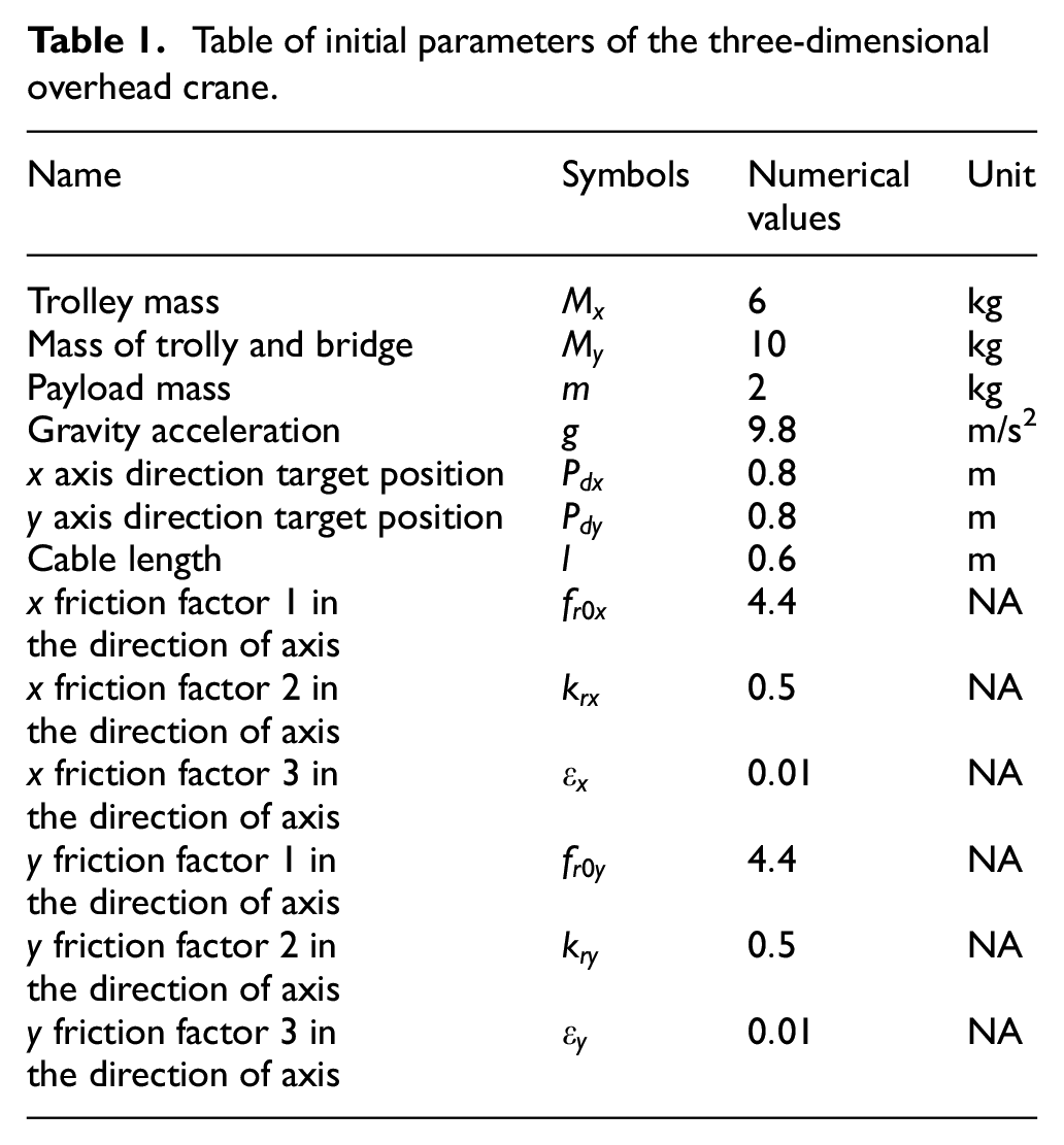
To reduce the influence of the non-stationary three-dimensional overhead crane starting swing angle, the parameters in the displacement deviation and angular deviation are set as
To ensure the integrity of the simulation under three-dimensional conditions, expressions for the energy coupled controller are given in equations (48)–(51), and expressions for the nonlinear tracking controller is shown in equations (52)–(59).
1) Energy coupled controller 24


Where
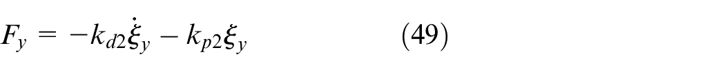
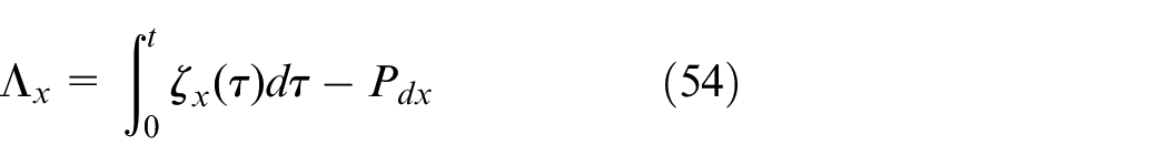
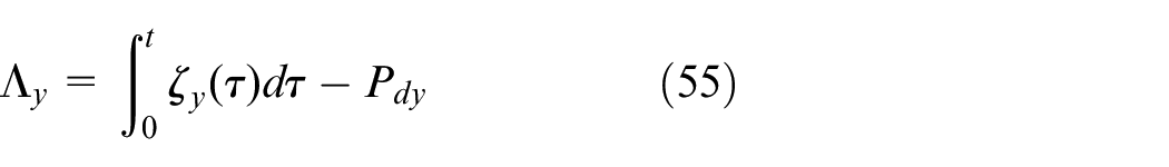
2) Nonlinear tracking controller 22
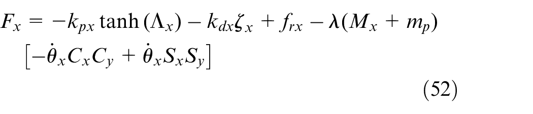
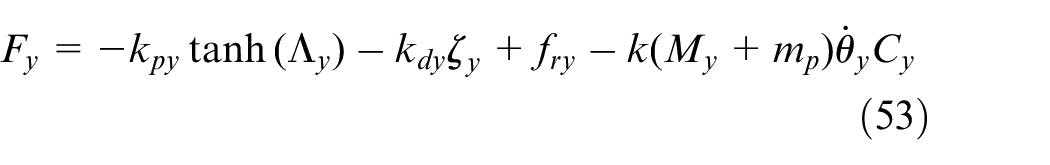
where


To effectively reduce payload swing, an S-shaped transport trajectory has been designed based on appropriate trolley and bridge velocities, accelerations, and adjustment parameters. This trajectory is then applied within a nonlinear trajectory tracking controller to achieve the desired smooth transport path for both the trolley and bridge. The design of the S-shaped transport trajectory for the trolley and bridge is as follows:
Where

After simulation and debugging, all three controllers were tuned to their optimal state. The control gains of the proposed controller, the enhanced coupled nonlinear tracking controller, and the nonlinear energy coupled controller are shown in Table 2.
(1) Comparative simulation analysis
Control gains of the three controllers.
In order to better demonstrate that the proposed control strategy exhibits superior control performance, we conducted simulation experiments on the controllers presented in this paper, the nonlinear tracking controller and the energy coupling controller. The comparative simulation results are illustrated in Figure 3, and specific parameter metrics are presented in Table 3.
Compare simulation results.
Control performance of the three controllers.
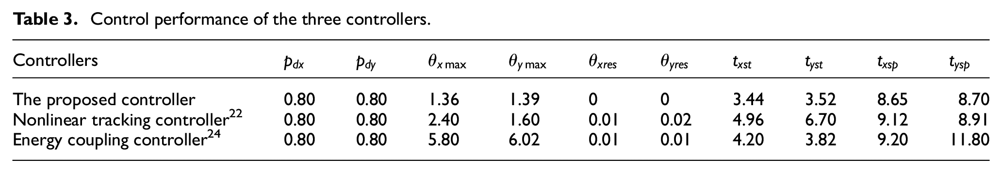
In Table 3,
From Table 3 and Figure 3, it can be observed that all three controllers effectively drive the trolley and bridge to the desired positions with minimal residual oscillations. In terms of the maximum payload swing angles, the proposed controllers yield 1.36° and 1.39° in the X and Y directions, respectively. These values are lower than the payload swing angles achieved by the nonlinear tracking controllers, 22 which are 2.40° and 1.60° in the X and Y directions. Furthermore, they are significantly less than the payload swing angles of 5.80° and 6.02° in the X and Y directions obtained with the energy coupling controller. 24 The thorough validation confirms that, compared to the other two controllers, the proposed controller, leveraging the time-varying damping resistance model, effectively suppresses the rapid surge in driving force of the overhead crane. It smoothens the velocity change curve, consequently restraining the significant load swing observed during the initial stages of the overhead crane operation. Additionally, the proposed controllers swiftly eliminate the payload swing angles, reducing them to within 0.5° within 3.44 and 3.52 s, outperforming the other two controllers. Further examination of Table 3 and Figure 3 reveals that the proposed controllers completely eliminate payload oscillations in the X and Y directions, transporting the payload to the desired positions in 8.65 and 8.70 s. This is in contrast to the nonlinear tracking controller, 22 which take 9.12 and 8.91 s, and the energy coupling controller, 24 which take 9.20 and 11.80 s, to dampen payload swing. Due to the introduction of the improved coupling signals, the displacement of the trolley and bridge has been strengthened to be more coupled with the corresponding load swing angles in both the X and Y directions. This ensures that the proposed controller can rapidly suppress payload swing during the transportation process, eliminating residual oscillations in the payload. The validation confirms the strong angular suppression capabilities of the energy coupling controller designed based on the improved coupling signals.
In summary, both in terms of swing suppression and driving the trolley and bridge during transport, the proposed controller demonstrates superior control performance compared to the other two controllers.
(2) Robust simulation experiments
Taking into consideration the practical environment, overhead cranes need to adjust their system parameters to adapt to various transportation requirements, which poses a significant challenge to the robustness of the proposed control strategy. To validate the strong robustness of the proposed controller, this paper conducts four sets of simulation experiments from four aspects: payload mass, cable lengths, transportation distance, and external disturbances. While keeping the system control gains unchanged, the simulations experimentally compare the effects of changing a single variable in order to verify the robustness of the proposed control strategy. The following are the four sets of simulation test cases:
1)
From the simulation results shown in Figure 4 for different payload masses, it can be observed that the proposed control strategy is still able to drive the trolley and bridge to the desired positions, with minimal changes in swing angles. Specifically, as the payload mass increases from 1.0 to 2.0 and 3.0 kg, the trolley transports the suspended payload to the desired position in less than 8.65 s, and the bridge transports the suspended payload to the desired position in less than 8.70 s, both without any positioning errors. During transportation, the maximum allowable payload tilt angle for the trolley’s transport direction is limited to 1.53°, and for the bridge’s transport direction, it is limited to 1.62°. Therefore, the proposed control strategy exhibits good robustness even when the payload mass varies.
1)
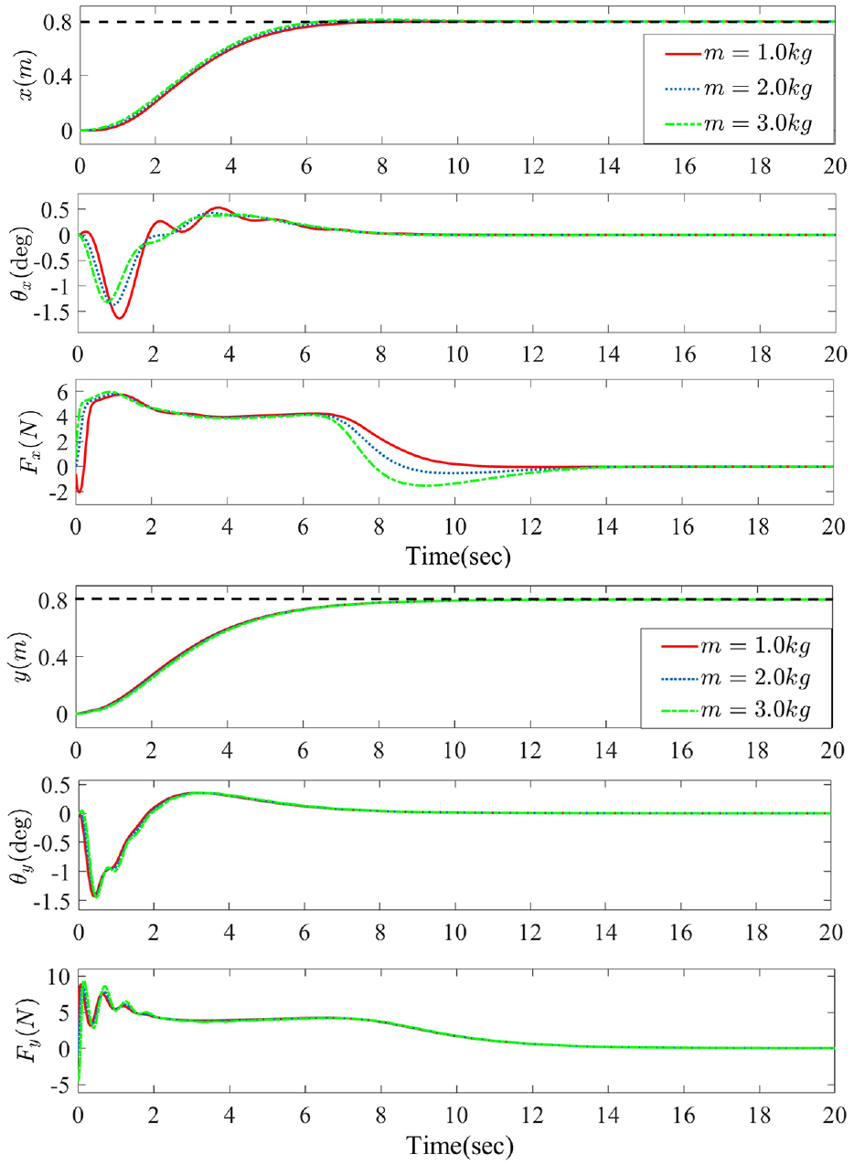
Simulation results for different payload masses.
From the simulation results shown in Figure 5 for different cable lengths, it can be observed that when the cable lengths vary, specifically increasing from 0.6 to 0.8 and 1.0 m, the trolley and bridge transport the suspended payload to the desired positions almost unchanged in time, all within 8.70 s, with no positioning errors. The swing angles for both the trolley and the bridge may increase with an increase in cable length, but they not exceed 1.8°, which fully demonstrates the strong robustness of the proposed control strategy during variations in cable lengths.
1)
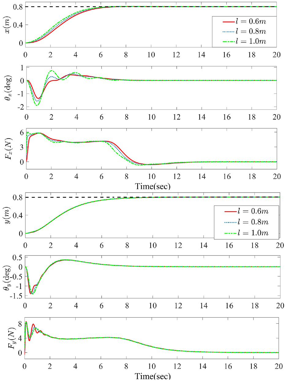
Simulation results for different cable lengths.
From the simulation results shown in Figure 6 for different transportation distances, it can be observed that as the transportation distance increases from 0.8 to 1.2 and 1.6 m, the time required for the trolley and bridge to reach the desired positions also increases. The trolley reach the desired position in 6.6, 7.0, and 7.4 s, while the bridge reach the desired position in 7.8, 8.4, and 8.8 s, respectively. However, both the trolley and the bridge are able to transport to the desired positions without any positioning errors. As for the maximum swing amplitude during transportation, it is controlled to be within 2.2° for the trolley direction and within 2.7° for the bridge direction. The proposed control strategy effectively eliminates payload swing and leaves no residual swing angles. Therefore, even when the desired transportation distance varies, the designed control strategy still exhibits good robustness.
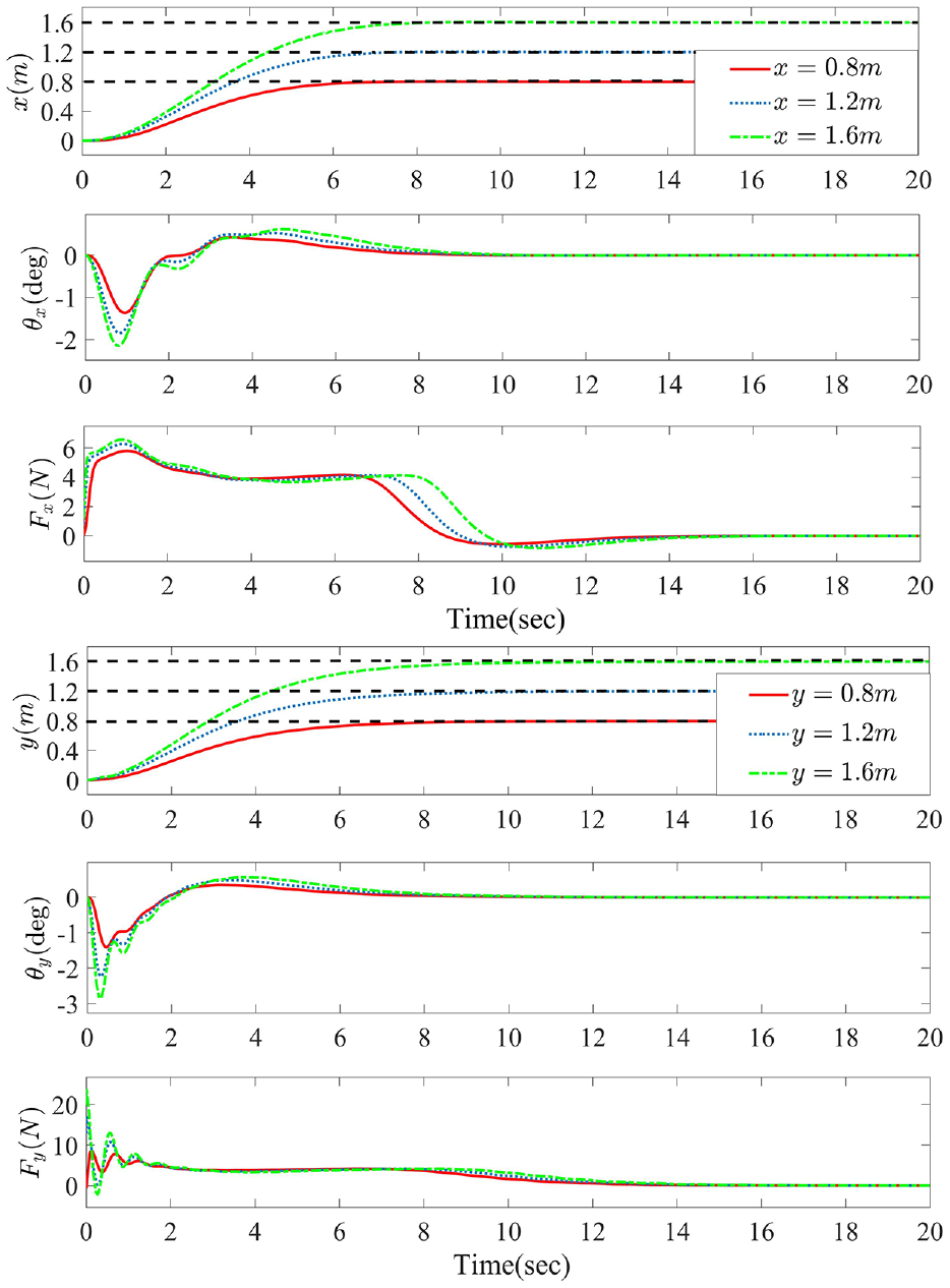
Simulation results for different transport distances.
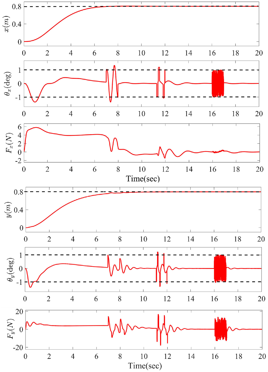
Simulation effect of different external disturbances.
From the simulation effect of different external disturbance in Figure 7, The amplitudes of both sinusoidal disturbances, pulse disturbances, and random disturbances are currently limited to approximately 1°. Furthermore, the designed control strategy rapidly restores stability after the disturbance ceases, and any residual tilt angles are promptly eliminated. This demonstrates that the proposed control strategy maintains good robustness in the presence of external disturbances.
(3) Non-stationary three-dimensional initial pendulum angle simulation experiments
Non-stationary three-dimensional initial swing angles can seriously affect the transport efficiency of overhead cranes. Different three-dimensional initial swing angles, including 3°, 6°, and 9°, are used to verify the proposed control strategy’s ability to suppress non-stationary initial swing angles without changing the control gain.
The simulation results are shown in Figure 8. For different non-stationary three-dimensional initial swing angles, the control strategy proposed in this paper can quickly control the swing amplitude within 0.5° within 3 s. By adjusting the reverse drive force, not only the non-stationary three-dimensional initial swing angle is effectively suppressed, but also the time to reach the set position and the positioning accuracy of the crane is not affected. This shows that the control strategy proposed in this paper has good initial swing angle suppression capability.
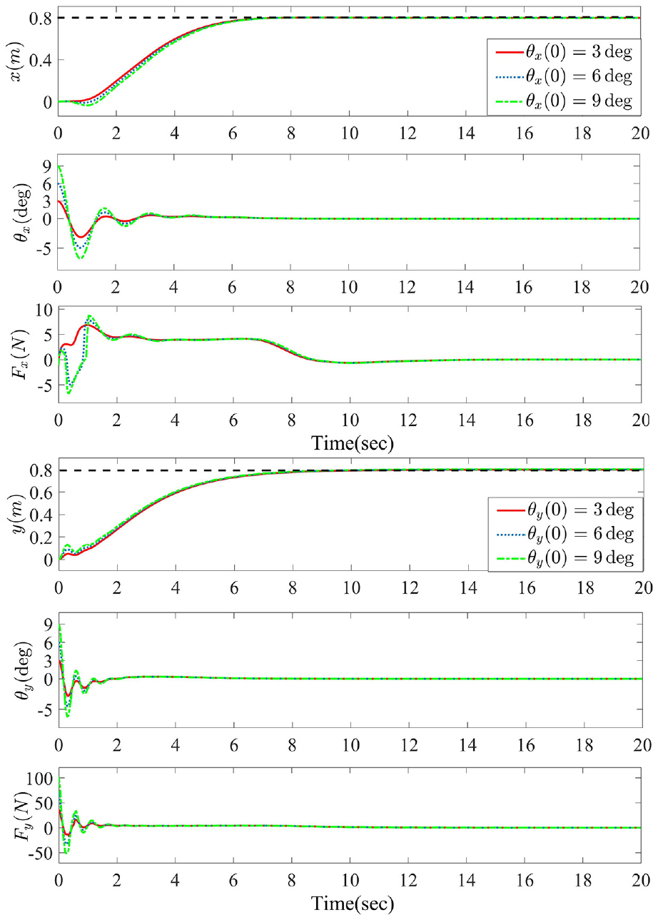
Simulation of different non-stationary three-dimensional initial pendulum angles.
Physical verification
To further verify the control performance of the control strategy proposed in this paper on a physical experimental platform, a three-dimensional overhead crane experimental system was built. The mechanical components of the experimental platform mainly consist of guide tracks, trolleys, bridges, hoisting ropes, payloads, and drive motors, among others. as shown in Figure 9. The experimental platform interfaces with the Matlab /Simulink program of the designed controller on the PC side, transmitting control commands to the motion control board (cy7c68013) via Ethernet. Simultaneously, it continuously receives real-time status information from the control board. The motion control board translates the control commands from the host computer into signals that can be executed by the DC servo motor drivers, driving the DC servo motors (MLDS3810) to move the mechanical components. The displacement of the trolley, hoisting rope, and bridge can be measured using encoders that are coaxial with the servo motors. The angle of the payload is measured by two mutually perpendicular optical encoders. These measurements, including displacement and angle information, are transmitted to the motion control board, which subsequently uploads the data to the host computer, enabling closed-loop control. The physical experimental effect of the proposed control strategy is derived under the premise that the crane system parameters remain unchanged and the control gain remains unchanged, and this effect is compared with the simulation experiment, as shown in Figure 10.
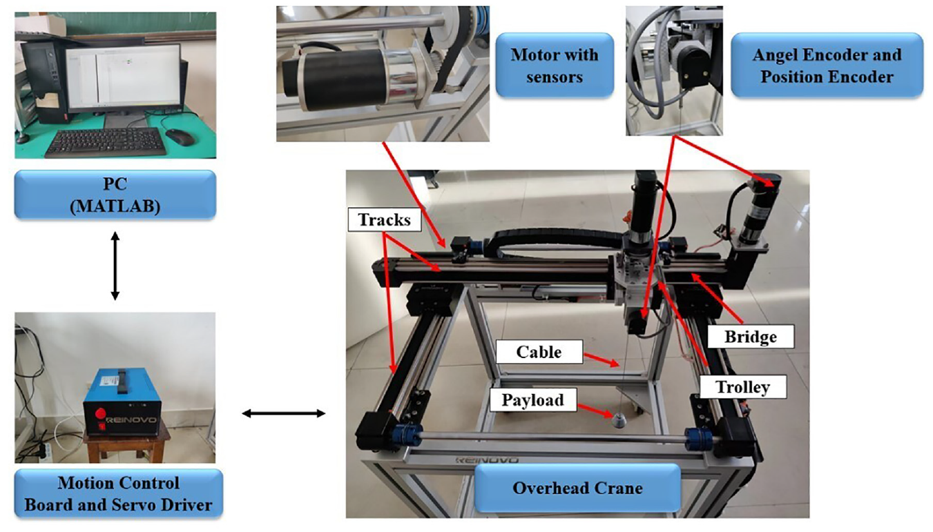
Three-dimensional overhead crane experimental system.
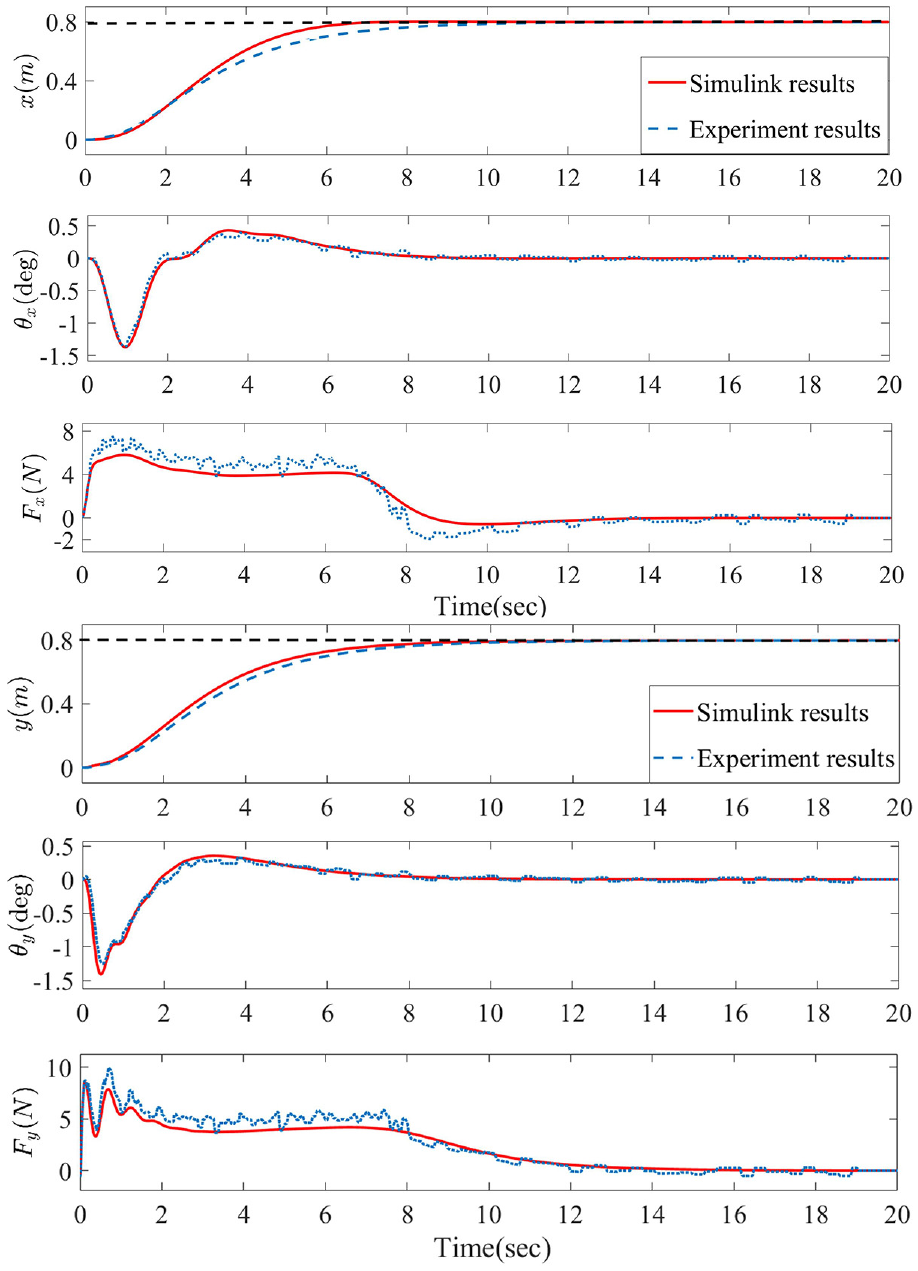
Comparative effect of physical and simulation experiments.
Figure 10 illustrates that, whether in the simulation or experimental curves, both the trolley and bridge achieve precise positioning of the specified payload. However, in the X-axis direction, the experimental curve takes 1.1 s longer to reach the desired position compared to the simulation curve, while in the Y-axis direction, the experimental curve lags behind the simulation curve by 0.6 s in reaching the desired position. In both the X-axis and Y-axis directions, the payload oscillation amplitudes of the experimental and simulated curves are nearly identical, at approximately 1.4°. In terms of the driving force in the X-axis and Y-axis directions, the experimental curve exhibits a difference of approximately 2N higher than the simulation curve during transport. However, when reaching the desired position, both of them nearly remain the same.
It can be observed that the trends of various physical quantities in both physical experiments and simulation experiments are consistent. Although the curves in physical experiments exhibit minor fluctuations, they do not affect the effectiveness of payload suppression. The reason for these small fluctuations in the physical experiments is attributed to unavoidable external disturbances and hardware limitations. In the physical experiments, the influence of factors such as the mass of the hook, the mass of the cable, and the superimposed effects of payload swinging during transport cannot be ignored, leading to a slightly higher driving force. Overall, based on the results of the comprehensive physical experiments mentioned above, the designed control strategy demonstrates good control performance and practical application value.
Conclusion
In this paper, we have proposed an improved anti-sway control strategy for a three-dimensional overhead crane with non-stationary enhanced pendulum angle suppression. Utilizing the devised displacement decay trajectories and angular decay trajectories, Tracking error trajectories for the initial position and initial angular displacement are strategically planned, leading to the establishment of a time-varying damping resistance model for the system. In addition, we have separately introduced coupling signals between the trolley’s displacement error and the payload swing angle, as well as the bridge’s displacement error and the payload swing angle. Based on these signals, we have designed an energy coupling controller. We have also demonstrated the asymptotic stability of the proposed control strategy through the application of Lyapunov methods and the LaSalle invariance principle. Finally, the proposed control strategy was validated for its favorable control performance, robustness, and adaptability through both simulation analysis and physical experiments. In general, the proposed sway control strategy effectively suppresses the initial swing angle of the overhead crane and provides efficient control of payload swing throughout the entire transportation process. This significantly improves transportation efficiency, reduces safety risks, and holds substantial practical value. However, the designed control strategy can only be applied to the single pendulum model. In actual transportation processes, the weight of the hook cannot be ignored, often resulting in a double pendulum model with significant and challenging-to-control oscillations. In the future, we will dedicate our efforts to constructing a more complex double-pendulum model to enhance the robustness of the sway control system and reduce the energy consumption of the overhead crane system.
Footnotes
Declaration of conflicting interests
The author(s) declared no potential conflicts of interest with respect to the research, authorship, and/or publication of this article.
Funding
The author(s) disclosed receipt of the following financial support for the research, authorship, and/or publication of this article: This work was supported by the Basic Scientific Research Project of Liaoning Provincial Department of Education (LJKMZ20220923) and Liaoning Provincial Department of Education 2023 Basic Scientific Research Project(JYTMS20231604).
Data availability statement
The data that support the findings of this study are available from the corresponding author upon reasonable request.