
Abstract
Unmanned aerial vehicle (UAV) has great application prospect because of its capability of three-dimensional space operation. The reliability of attitude and heading reference system (AHRS) for UAV attitude estimation is crucial for the application of UAV. When a UAV is subjected to unknown electromagnetic interference and force interference in flight, its attitude detection system can suffer from reduced accuracy or even failure. In this paper, a fuzzy adaptive complementary filter (CF) for attitude estimation based on norm judgment is proposed to solve the problem that the sensor is easily disturbed by the complex flight environment and the fixed filter parameters are difficult to obtain the UAV attitude accurately under different flight states. Firstly, the correction model of the gyroscope, which includes four filter parameters, namely accelerometer weight, magnetometer weight, proportional gain P and integral gain I, is established. Secondly, the influence of the four parameters on the estimation accuracy is analyzed. Finally, the adaptive adjustment rules are designed to adjust the filter parameters online and thus achieve the accurate and reliable measurement of UAV attitude. The feasibility of the proposed algorithm is verified through static, dynamic and interference experiments with the specially designed AHRS test platform. And the results show that the attitude estimation algorithm designed in this paper can ensure the high accuracy of the system in both steady state and high-speed rotation, shield the pitch and roll angles from the acceleration of motion, and keep the yaw angle from the external magnetic field.
Keywords
Introduction
Compared with other unmanned equipment, UAV can upgrade the working space from two-dimension to three-dimension, so the UAV technology and its application have developed rapidly in recent years. 1 However, at present, most of UAVs are mini-micro and mainly aimed at the consumer market while few of them are used in professional fields, such as material transportation, high-altitude fire protection, power line inspection and so on. The main reason is that the flight reliability, which is straight affected by the accuracy and the stability of AHRS, is difficult to meet the requirements.
AHRS is a multi-sensor system including Micro-Electro-Mechanical System gyroscope, accelerometer and magnetometer. 2 In the real flight, UAV is affected by the following factors. (1) The poor low frequency characteristics and serious temperature drift of gyroscope tend to accumulate the error quickly when the UAV is in low speed or steady state. (2) Although the magnetometer and accelerometer have good low-frequency characteristics, the measured value of the former is easily disturbed by the surrounding magnetic field, and the rotation angle around the geomagnetic line cannot be detect. Besides, the measurement accuracy of the latter is only effective in steady state and the rotation angle around the gravitational acceleration direction cannot be detect. The factors mentioned above make it difficult to give accurate attitude information of UAV because of its complicated dynamic characteristics. To improve the accuracy of AHRS, many researchers adopt the method of fusing the signals of gyroscope, accelerometer and magnetometer, in which Kalman Filter (KF)3–5 and Complementary Filter are the two most popular sensor fusion schemes. Besides, the neural network-based pose estimation algorithm 6 is also a future-oriented development in the field of pose estimation, but since it requires more computational resources and a richer dataset, 7 it needs further development of microcontroller hardware and dataset before it can be practically and effectively applied.
However, KF requires that the system is linear and the noise is white noise, which is difficult to realize in many cases. To deal with the large amount of colored noise in sensors, many scholars have developed various extended and derived algorithms based on Kalman filter algorithm. Sabatelli et al. 8 designed a novel two-stage filter based on extended Kalman filter (EKF). Accelerometer data are used in the first stage, and Magnetometer data for angular position correction, which effectively improves the flexibility of calculation and robustness to magnetic anomaly, are used in the second stage. However, the accuracy of EKF is limited because it approximate nonlinear function by linear ways. For nonlinear systems, unscented Kalman filter (UKF) has more advantages. 9 Simulation results show that UKF has faster convergence speed, higher filtering accuracy and more stable estimation performance when compared with EKF. The algorithm based on Kalman filter requires UAV to have stable flight state, which is difficult to achieve, resulting in poor long-term reliability in practical application. In view of the defects of Kalman filter used in attitude estimation, Mahony et al. 10 proposed an explicit complementary filter (ECF) for UAV attitude estimation. In this method, the accelerometer was used to compensate the gyro drift, and then the compensated angular velocity was integrated to obtain the attitude angle. The algorithm has good performance on roll angle and pitch angle estimation, but the yaw angle correction is low.
Therefore, on the basis of Inertial measurement unit (IMU) compensation filter, Sheng and Zhang 11 introduced magnetic field sensor for yaw angle calibration, gave a complementary filtering scheme in the form of direction cosine, then established a complete AHRS three-dimensional attitude measurement system, and finally acquired good feedback. achieved good results. In essence, these algorithms used the low-frequency characteristics of accelerometer and magnetometer to compensate the cumulative error of gyroscope, but the fixed filter coefficient in the algorithm is difficult to ensure that the system has high accuracy both in high-speed and low-speed situations. To address this issue, Poddar et al. 12 designed an adaptive complementary filtering algorithm (ACF) based on the Eulerian angle description, which solves the problem that the complementary filtering algorithm is difficult to obtain the optimal motion attitude angle in multiple motion situations due to fixed parameters; and Yan-Jun et al. 13 verified the relative superiority of the algorithm in filtering accuracy in static and dynamic filtering effect experiments. However, the method does not address the problems of external non-geomagnetic magnetic field interference and motion acceleration interference.
In light of the above research, a norm-based fuzzy adaptive complementary filter attitude fusion algorithm is proposed to solve the long-term reliability problem of AHRS. Compared with the shortcomings of traditional complementary filtering, that is, it is difficult to meet the pose estimation in all states when the complementary parameters of the filter PI controller are fixed, the introduction of fuzzy control algorithm can fuzzy adaptive adjustment of PI parameters for the characteristics of different motion states to achieve adaptive complementary filtering and improve the adaptability and reliability of the algorithm. In this paper, we innovatively propose to incorporate the real-time evaluation criteria of the reliability of accelerometers and magnetometers (mainly the judgment of the parity of the measured values of the two sensors) into the fuzzy control rules of the attitude estimation algorithm in the case of acceleration disturbances caused by unknown forces and external non-geomagnetic magnetic field disturbances to ensure the reliability and accuracy of the attitude estimation algorithm in complex flight environments. The basic idea is to firstly adaptively adjust the accelerometer weight according to the accelerometer measurement value norm to deal with the influence of UAV’s unsteady motion on the accelerometer information; then, adaptively adjust the magnetometer weight according to the magnetometer measurement value norm to deal with the interference of the external non geomagnetic magnetic field on the magnetometer; lastly, the PI coefficients are adjusted adaptively to make the filter have appropriate cut-off frequency and damping coefficient in different motion states of UAV, according to the measurement value norm of the gyroscope and the system deviation obtained by the complementary filter. The algorithm both considers the interference of complex environment on sensing and overcomes the adaptation problem of fixed filtering parameters under the dynamic change of UAV, providing a theoretical basis for highly reliable attitude feedback.
The structure of remaining of this paper is as follows: in the second section, the quaternion based space attitude description method of UAV is deduced and the initial alignment of AHRS is completed; in the third section, the complementary filter based on quaternion is designed; in the fourth section, adaptive adjustment rules are designed according to accelerometer norm, magnetometer norm and gyroscope norm; in the last section five, AHRS and the test platform are built, and static state dynamic and interference experiments are designed.
Attitude representation and initial determination
Attitude representation
Defining the global North-east-down (NED) reference frame as the navigation frame (
And the orthogonal axis set of the body frame (
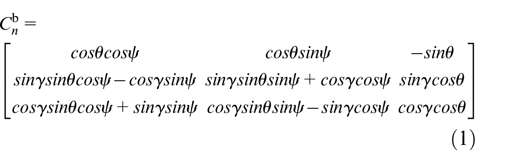
The formula (1) is not suitable for full attitude estimation for there exist a lot of trigonometric functions, which increase the difficult on real time calculation, and the degradation phenomenon may appears when the pitch angle θ closing to 90°.
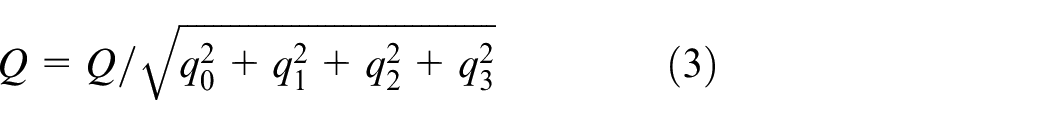
In the attitude angle expressing, the quaternion is more flexible than Euler function and could avoid the angle singularity problem, which make the system better linearized. Moreover, it’s easy to transform quaternion into other rotation representation methods, such as rotation matrix or Euler angle sequence, and all of these features popularize the quaternion in the robot field.
A quaternion
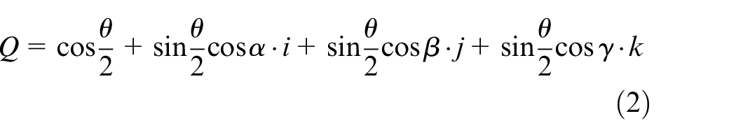
Since
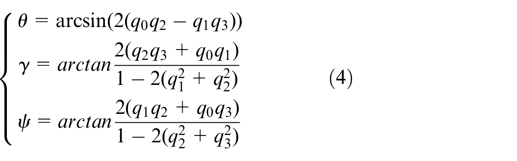
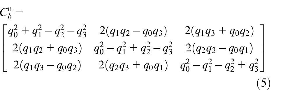
According to the X-Y-Z sequence of Euler angle, a standard formula is used to convert the quaternion angle rotation representation to Euler angles. The roll θ, pitch
According to equations (1) and (4), the rotation matrix from
Attitude initialization
The data measured by each sensor fixed on the UAV are based on
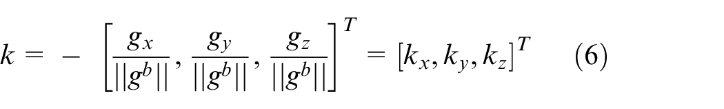
Before taking-off, the UAV is in a static state and the measured data of accelerometer is the projection of the supporting force which is opposite to gravity on
Let
The measured value of magnetometer
Considering the magnetic inclination, the geomagnetic field vector
Vector projection of magnetometer.
Therefore, the vertical downward gravity vector obtained by the accelerometer would be in the same direction with the

Then the vectors
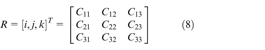
The quaternion representing the initial attitude of UAV can be obtained from the following equations.
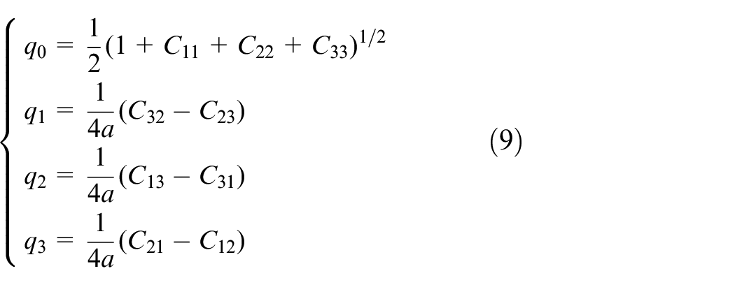
According to the WMM geomagnetic model provided by National Oceanic and Atmospheric Administration, the magnetic declination
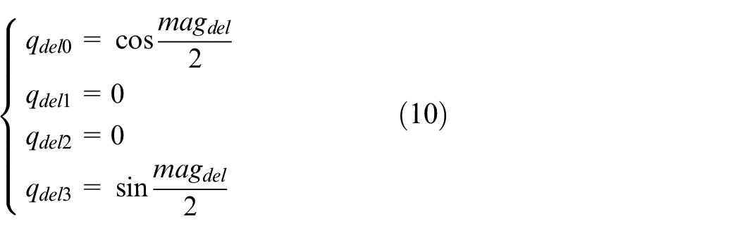
The quaternion of magnetometer offset could be defined as
According to the definition of quaternion, the quaternion variation after yaw is as follows:
The quaternion transformation is multiplied by the initial quaternion. According to the physical meaning of quaternion multiplication, it is equivalent to the rotation of
Quaternion differential equation
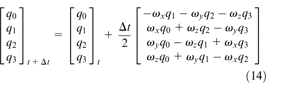
The gyroscope data is used as the input of quaternion differential equation to update quaternion. According to Coriolis theorem and quaternion multiplication representation of coordinate transformation, the quaternion differential equation using gyroscope data as input is obtained:
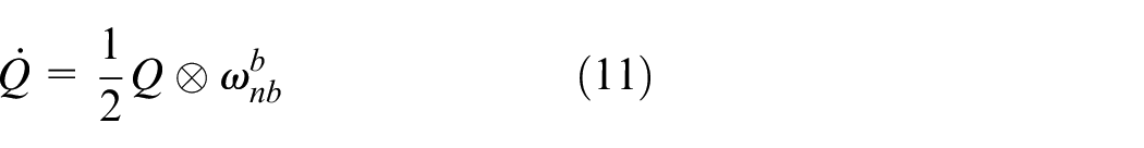
where,
⊗ represents quaternion multiplication.
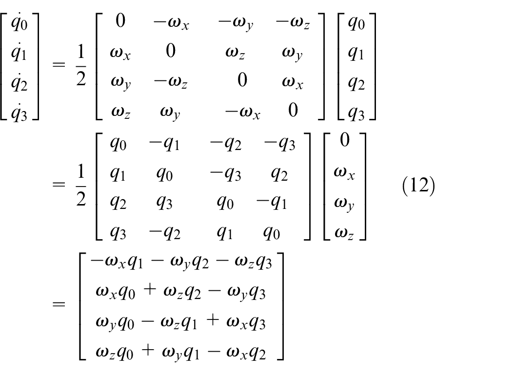
Matrix form:
Through the first order Runge Kutta method:
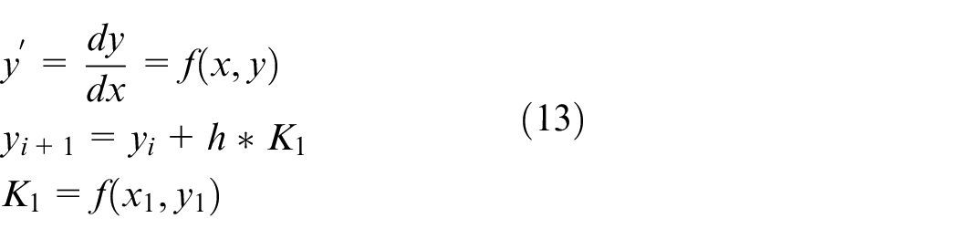
The iterative equation of quaternion can be obtained
Matrix form:
Where,
The updated quaternion is obtained and the next iteration is carried out.
Complementary filter
Complementary filter principle
Taking advantage of the good high-frequency characteristics of gyroscope and the good low-frequency characteristics of accelerometer and magnetometer, complementary filter uses accelerometer and magnetometer to compensate the drift of the gyroscope and then improves the attitude measurement accuracy. The specific methods are as follows:
The gyroscope data
In order to reduce the influence of sensor noise, eliminate the static error and improve the response speed, PI control is added to compensate
Based on quadratic complementary filter principle.
Fusion of gyroscope and accelerometer
The measured
The calculated value
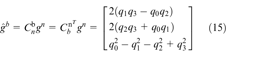
Where,
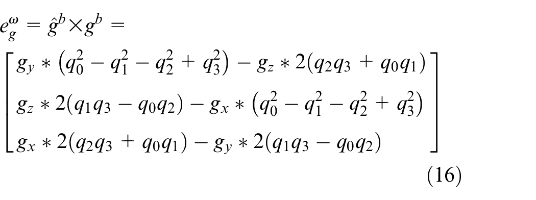
The error between vectors can be calculated by the cross product of vectors. With the vector product of gravity vector
Fusion of gyroscope and magnetometer
The measured
In
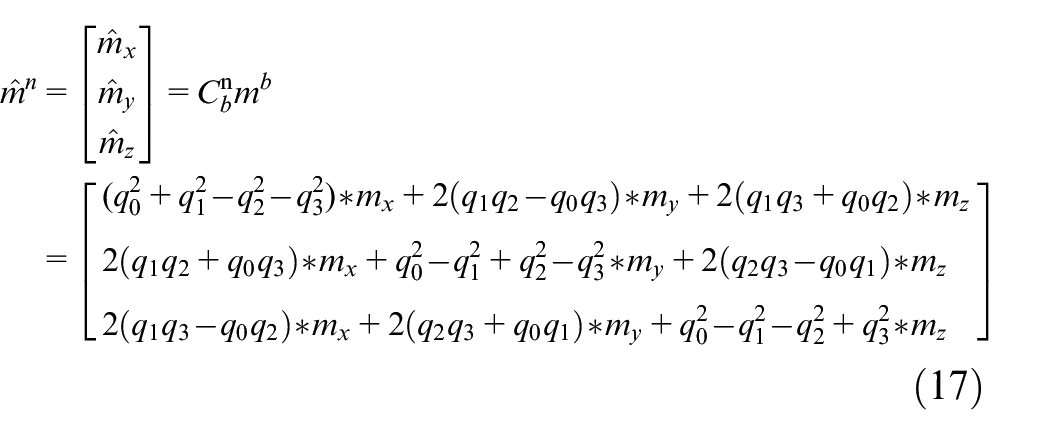
Where,
The magnetic deflection angle could be estimated from the calculated tangent value of

A new vector is constructed, and
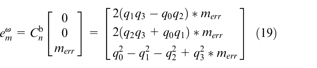
Compensation of gyroscope
The calibration weight of accelerometer is defined as

PI control is applied to the compensation
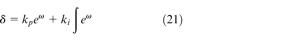
where
Finally get the corrected gyroscope data as:

where,
The modified gyroscope data
The above complementary filter based on quaternion can effectively reduce the calculation amount of attitude estimation, and better realize the data fusion of AHRS sensors. However, in practical engineering applications, it is difficult to obtain satisfactory results by using a set of fixed filter parameters to adapt to various flight states and complex environmental disturbances. Therefore, it is necessary to adjust the filter parameters online adaptively according to the environmental interference and the dynamic changes of UAV to improve the accuracy and robustness of the solution.
Fuzzy adaptive complementary filter
Correction model
Substituting equations (20) and (21) in (22), a correction model of gyroscope is proposed:
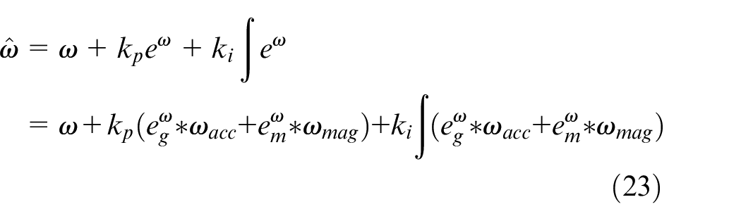
According to the solution principle and the gyroscope correction model, three factors affecting the accuracy of the solution are summarized here:
(1) If the aircraft is in the variable speed flight state, the accelerometer would be disturbed by the motion acceleration, and the magnitude and direction of the measured acceleration vector might deviate from the gravity vector that is required for the measured value in the process of calculating the pitch and roll compensation
(2) If there is non-geomagnetic interference in flight environment, the magnitude and direction of the measured magnetic field vector may deviate from the geomagnetic vector that is required for the measured value in the process of calculating the yaw compensation
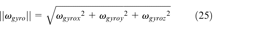
(3) The
The larger
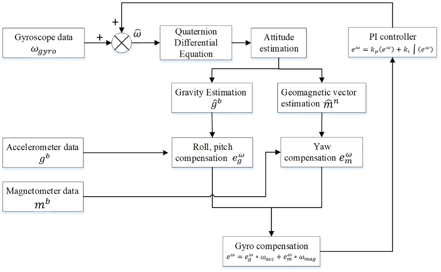
Therefore, a fuzzy control adaptive complementary filter based on norm judgment is designed in this paper. The algorithm structure diagram is shown in Figure 3. Firstly, a weight adaptive adjustment scheme is designed, which can adjust the accelerometer calibration weight adaptively according to the accelerometer measurement value norm
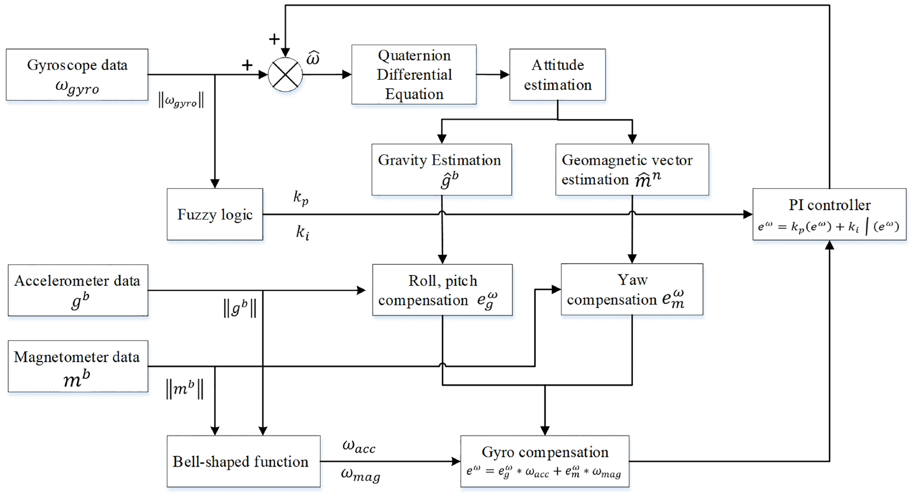
Fuzzy control adaptive complementary filter based on norm judgment.
Tuning of
and
When the UAV has motion acceleration, the problem described in the factor (1) will arise. Therefore, as the accelerometer norm
Let
Considering the sensor noise error
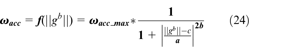
where,
The curve of the bell-shaped function
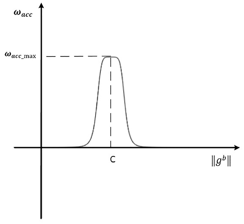
Curve of bell-shaped function.
The bell-shaped curve describes the variation of the accelerometer weight
Similarly, when there is external magnetic interference around the system, the problem described in the factor (2) will arise.
Tuning of PI coefficients
When the filter coefficients
Tuning of proportional gain P
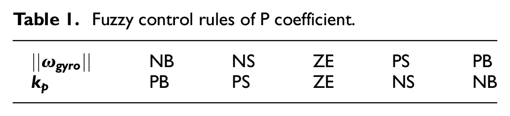
In this section, the fuzzy control rules are used to adjust the coefficients
Taking the
The membership function for engineering applications is not unique. In this paper, the triangular membership function is selected as the membership function of the input and output variables based on the factors of the time for the microprocessor to realize fuzzification and defuzzification in the design, the memory space occupied by the rule look-up table, and the control effect.
In this section, fuzzy control rules, the basis of fuzzy reasoning, are established as follows:
When the system runs in low rotate speed or keeps steady, the
When the system rotates in high-speed, the
Thus, the fuzzy control rules of P coefficient are shown in Table 1:
Fuzzy control rules of P coefficient.
Tuning of integral gain I
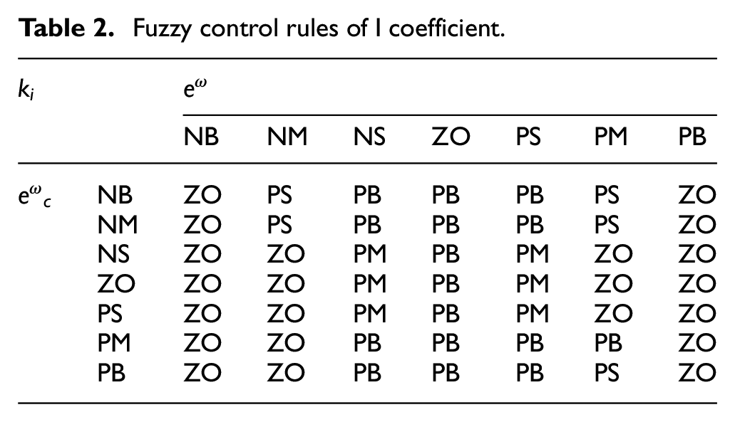
The integration coefficient also determines the calibration effect of the direction cosine matrix in the complementary filtering algorithm and affects the performance of the attitude solving algorithm. A larger integration factor can quickly eliminate the steady-state error of the system in the steady state, but it leads to a larger overshoot when the system deviation is large. In this section, according to the system deviation
The absolute value of the system deviation
The membership functions of input and output variables are still the triangular model function. The fuzzy control rules established in this section are as follows:
When
When the
When the
According to the above principle, PID coefficients adaptive principle and operation experience, the fuzzy control rules of I coefficient are shown in Table 2:
Fuzzy control rules of I coefficient.
The core design of PI coefficient fuzzy controller has been completed so far. The last thing needed for obtaining the specific value of the optimized PI coefficient and completing the adaptive adjustment of the PI coefficient is clarifying the output of the fuzzy. This method overcomes the attitude error caused by the measurement of high frequency part of accelerometer sensor and low frequency part of gyroscope.
Experimental methods and results
In this section, the test platform and UAV hardware platform based on open source flight control Pixhawk are built. The static, dynamic and interference experiments are designed and conducted to verify the stability and accuracy of the algorithm by comparing the results of adaptive complementary filter, traditional complementary filter, in which the best parameters of the adaptive complementary filter is fixed, and simple gyroscope integration.
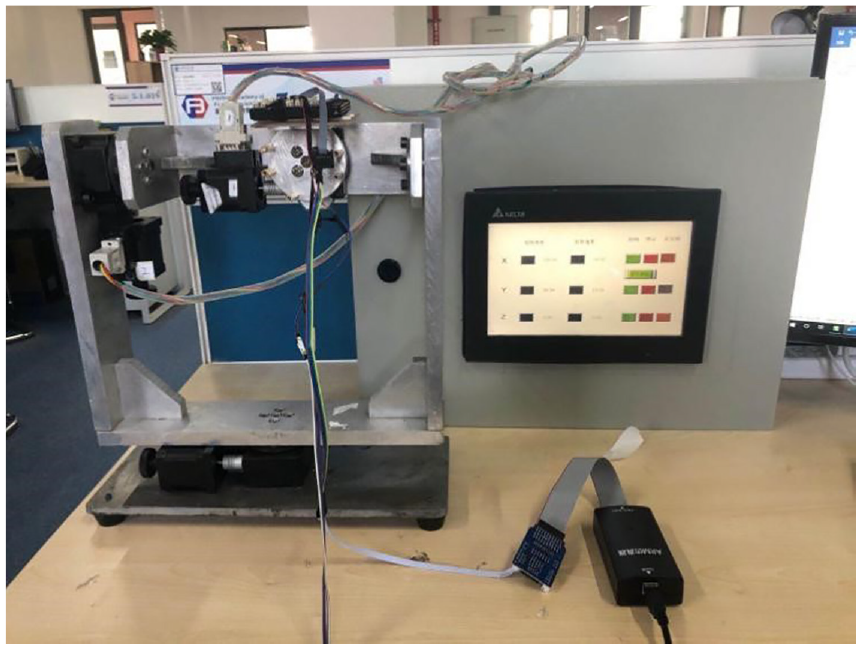
Construction of AHRS hardware platform
The open source flight controller Pixhawk, which uses a 32-bit STM32F427 chip with FPU as the main controller and has a fault coprocessor chip with a type of STM32F103, is adopted for the platform. The sensors embedded in Pixhawk include ST’s MicroL3GD20H 16-bit gyroscope and Micro LSM303D 14-bit accelerometer/magnetometer, InvenSense Corp.’s MPU 6000 series 3-axis accelerometer/gyro, and MEAS’s MS5611 barometer.
By spi communication, the raw data from the sensor is transmitted to the main controller, in which the attitude solution is completed. Pixhawk transmits the experimental data (including sensor data and settlement results) back to the host computer in real time by J-link simulator. The serial port drawing software is installed in the host computer, so that the data returned by Pixhawk can be displayed in real time in the host computer.
Construction of test platform
The test platform is composed of three electric rotating turntables: yaw axis, pitch axis and roll axis and its overall structure is shown in Figure 5.
Triaxial electric test turntable.
Its driving part includes three stepper motors, which is control the rotation of the yaw, pitch and roll direction of the experimental table from the bottom to the top respectively. Through the test, the error of the test bench is about 1° per rotation of 100 laps, so the accuracy of the test bench is 1/36,000° per degree, as shown in Figure 6. The PLC control box is designed to realize the constant speed and the fixed point rotation of the experimental table. The hardware platform is fixed at the connecting plate of the experimental platform, and the various flight attitude of the aircraft can be simulated by controlling the turntable motion.

Laboratory dials.
Dynamic and static experiments
The experiment in this section compares three algorithms of traditional complementary filter, gyro direct integration and adaptive complementary filter. And among them, the dynamic and static tests are used to verify whether the adaptive algorithm can maintain a good and consistent attitude detection accuracy in different motion states of the body.
Static experiments
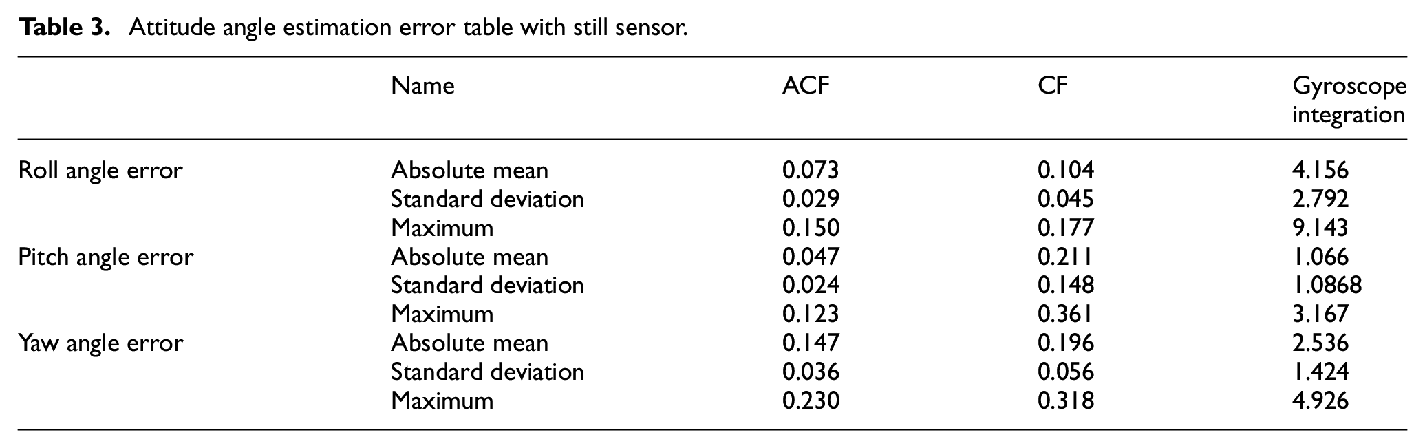
Set the sensor in static position and hold the sampling frequency at 200 Hz and the sampling time at 300 s. Since the actual angle does not change under static conditions, the solution error is the difference between the estimation result and the initial angle. The standard deviation and the maximum value of attitude angle error calculated by three algorithms under static condition are listed in Table 3.
Attitude angle estimation error table with still sensor.
The roll angle, pitch angle and yaw angle errors solved by the three algorithms are shown in Figures 5 to 7, respectively.
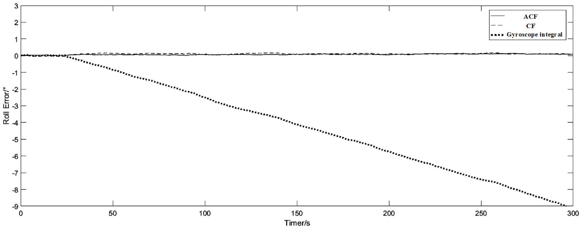
Static roll angle estimation error.
From Table 3, it can be concluded that the mean value of the solution error of adaptive complementary filter in roll, pitch and yaw direction are 0.073°, 0.047°, and 0.147° respectively, and the corresponding standard deviation is 0.029°, 0.024°, and 0.036° respectively, which are smaller than the other two algorithms. From Figures 7 to 9, it can be seen that there is no attitude drift in solution results of traditional complementary filter and adaptive complementary filter, while the cumulative error of gyroscope integration increases and deviates from the real angle quickly.
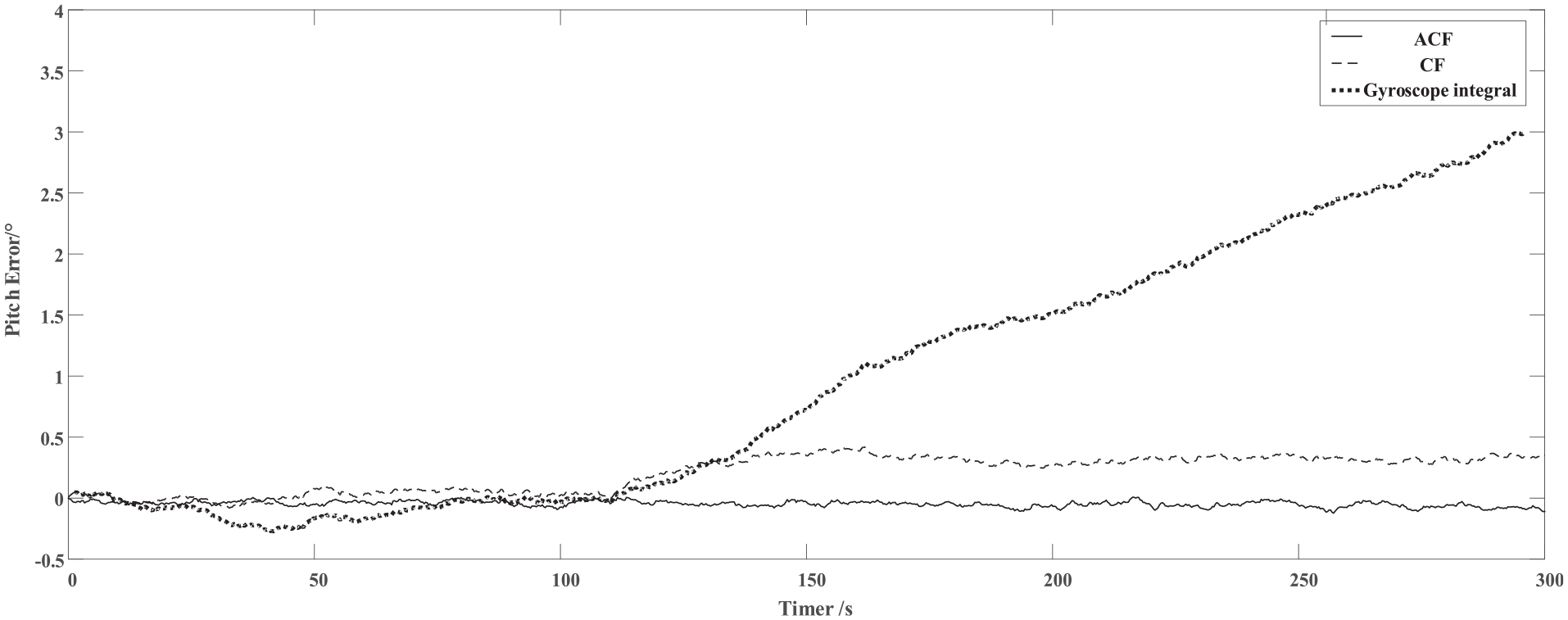
Static pitch angle estimation error.
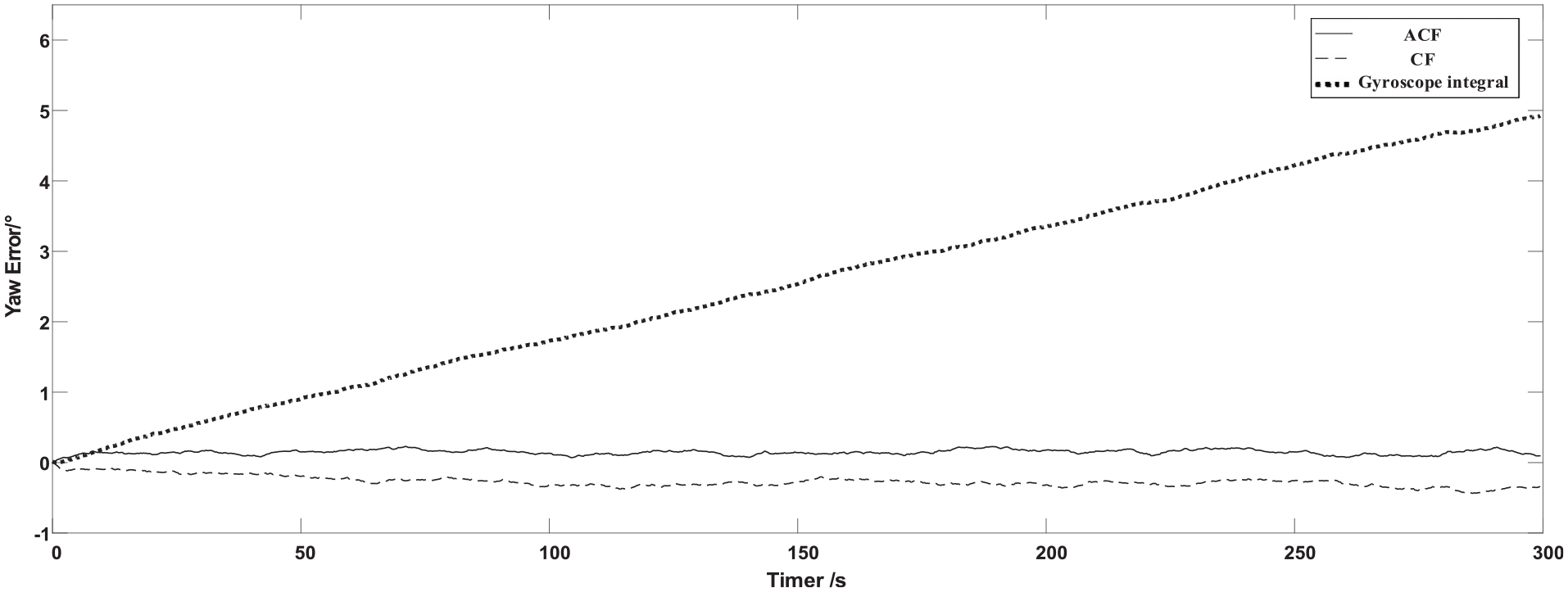
Static yaw angle estimation error.
Dynamic experiments
The dynamic test is divided into two cases including the case of slow attitude change (setting the test turntable speed of 0.5°/s) and the case of fast attitude change (setting the test turntable speed of 20°/s).
For most aircrafts, their pitch and roll control angle is smaller than 45° in the real flight process. Thus the measurement range of roll and pitch angle is −45∼45°, and the measurement range of yaw angle is 0–360°. Since the electric turntable can operate at a uniform speed, it is not difficult to deduce that the function curve of the real angle

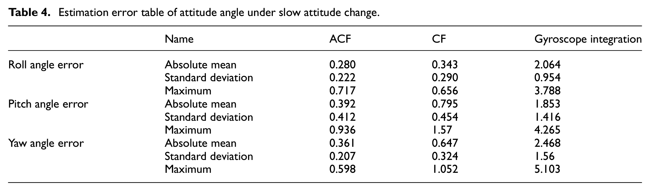
From equation (26), we can get the real angle of the whole process. By subtracting the estimated angular position from the real angular position, the solution error of the whole process can be obtained. The absolute mean value, standard deviation and maximum value of attitude angle error calculated by the three algorithms in slow attitude transformation rate of 0.5 °/s are listed in Table 4.
Estimation error table of attitude angle under slow attitude change.
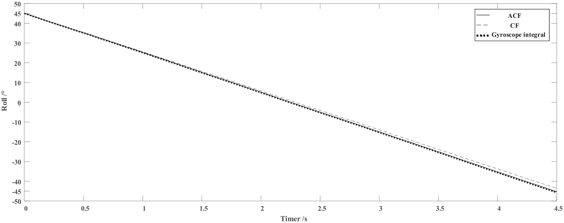
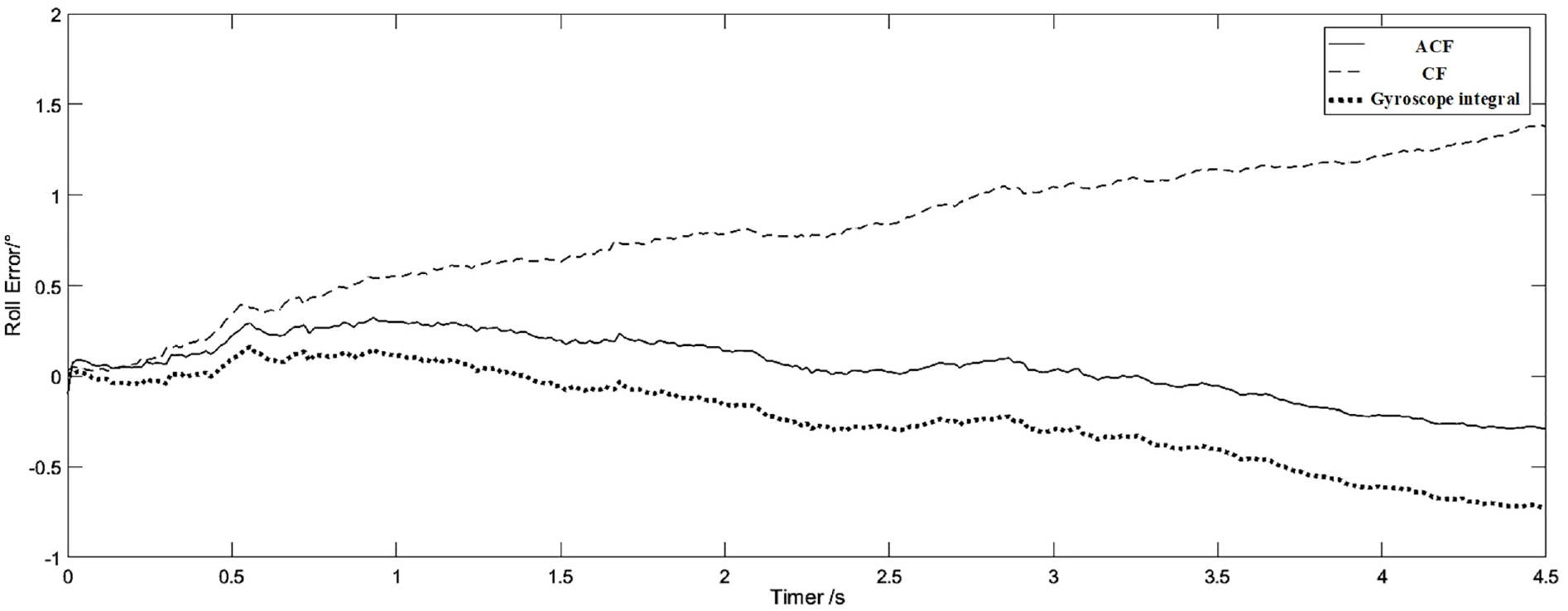
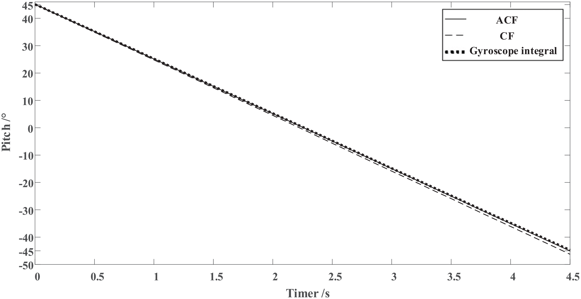
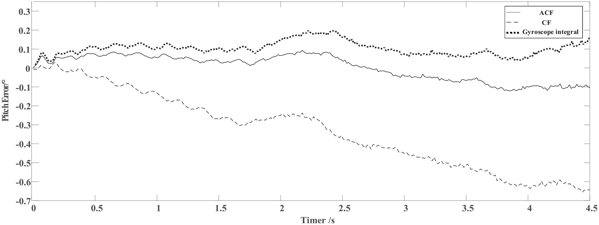
As the attitude changing slowly, the data and error of roll angle solution obtained by the three algorithms are shown in Figures 10 and 11, respectively; the data and error of pitch angle solution are shown in Figures 12 and 13, respectively; and the data and error of yaw angle solution are shown in Figures 14 and 15 respectively.
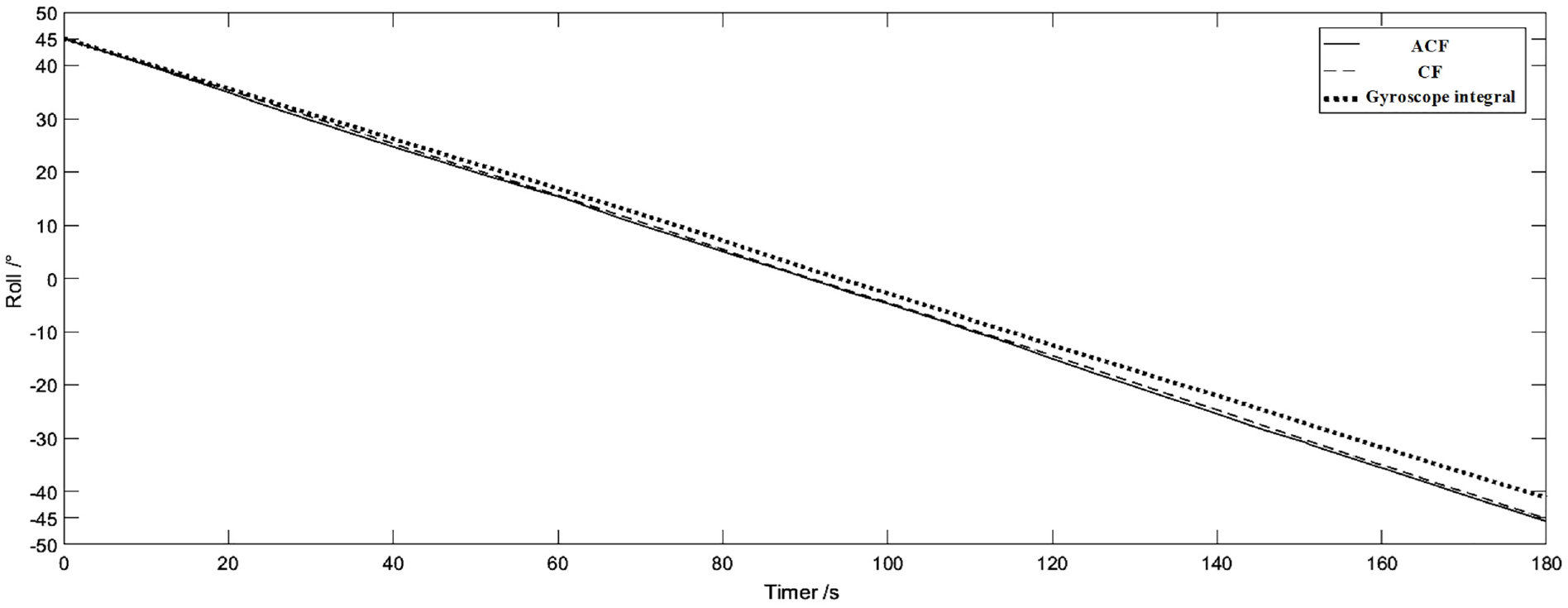
Roll angle estimation data.
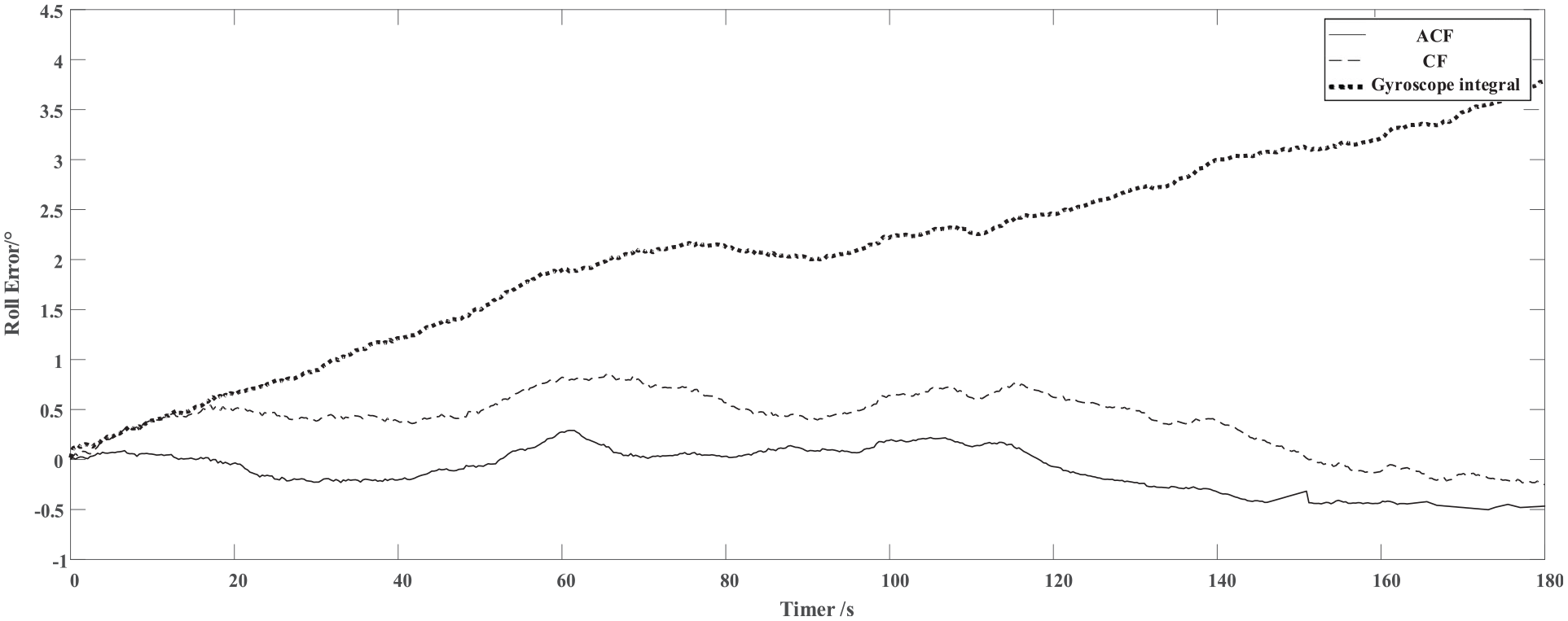
Roll angle estimation error.
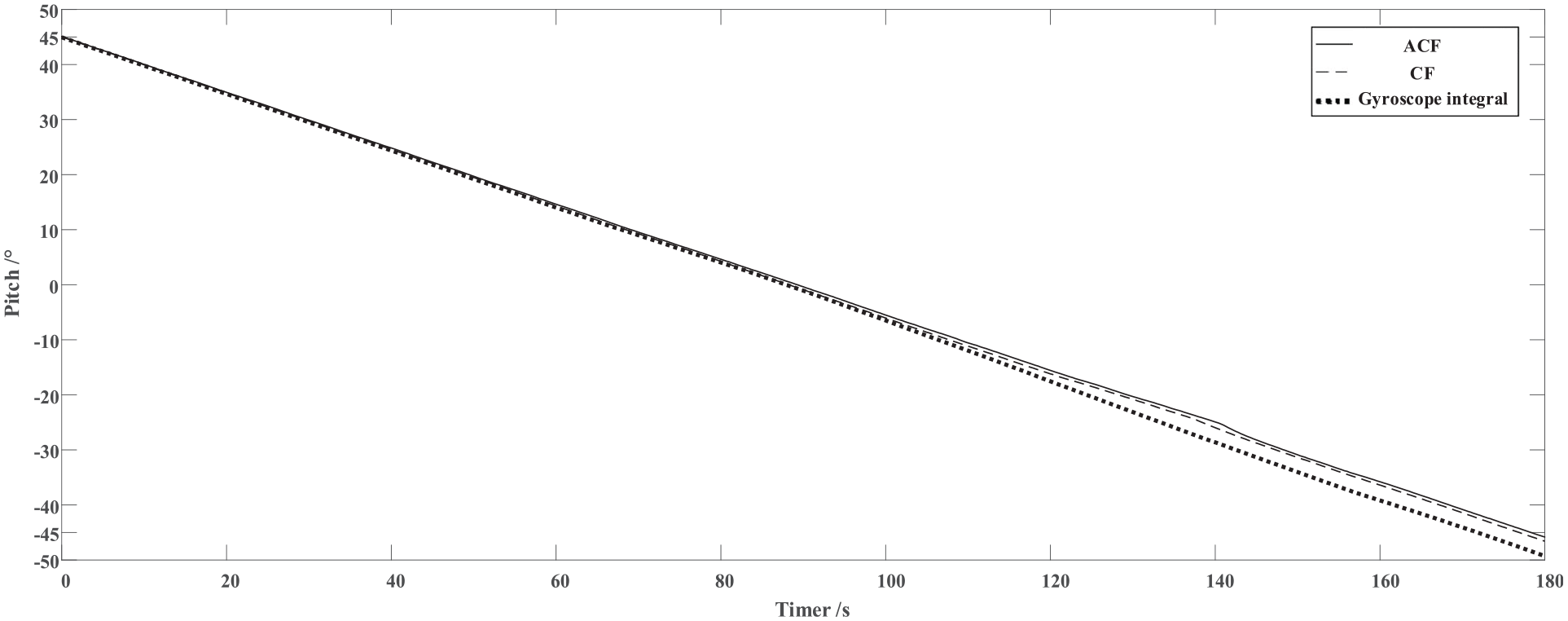
Pitch angle estimation data.
Pitch angle estimation error.
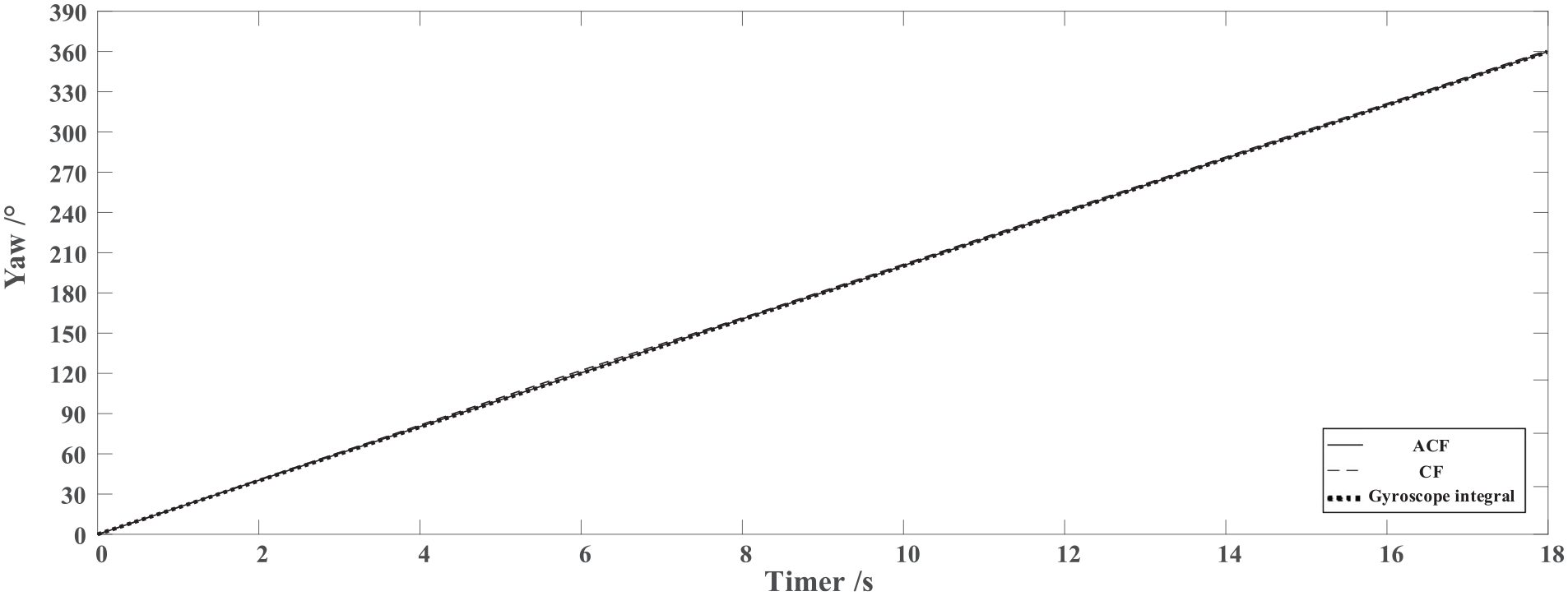
Yaw angle estimation data.
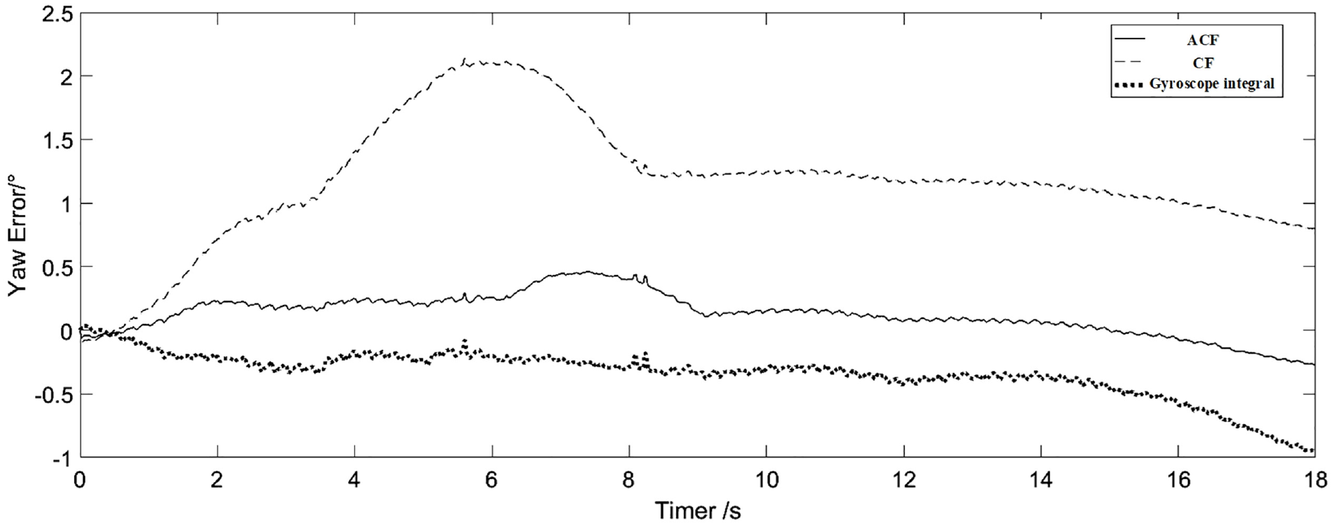
Yaw angle estimation error.
From Table 4, it can be obtained that the mean value of the solution error of adaptive complementary filter in roll, pitch and yaw direction, which are 0.280°, 0.392°, and 0.361°, and the error standard deviation, which are 0.222°, 0.412°, and 0.207° respectively, are both obviously smaller than the other two algorithms. It can be seen from Figures 9, 11, and 13 that the attitude drift does not happen to the solution results of traditional complementary filter and adaptive complementary filter, while the cumulative error of gyroscope integration increases and quickly deviates from the real angle.
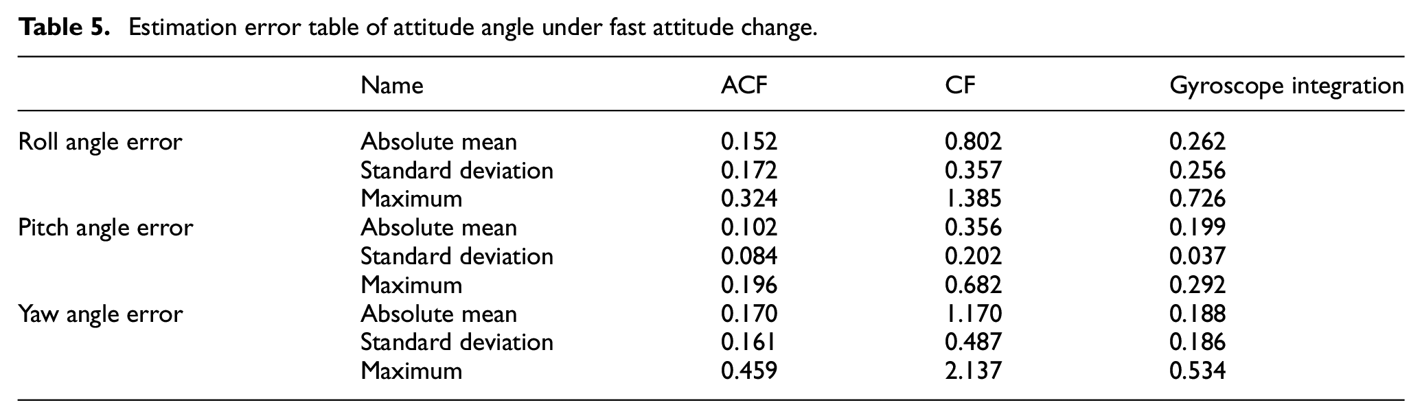
Table 5 lists the absolute mean, standard deviation, and maximum of the attitude angle errors calculated by the three algorithms when the attitude changes rapidly (20°/s).
Estimation error table of attitude angle under fast attitude change.
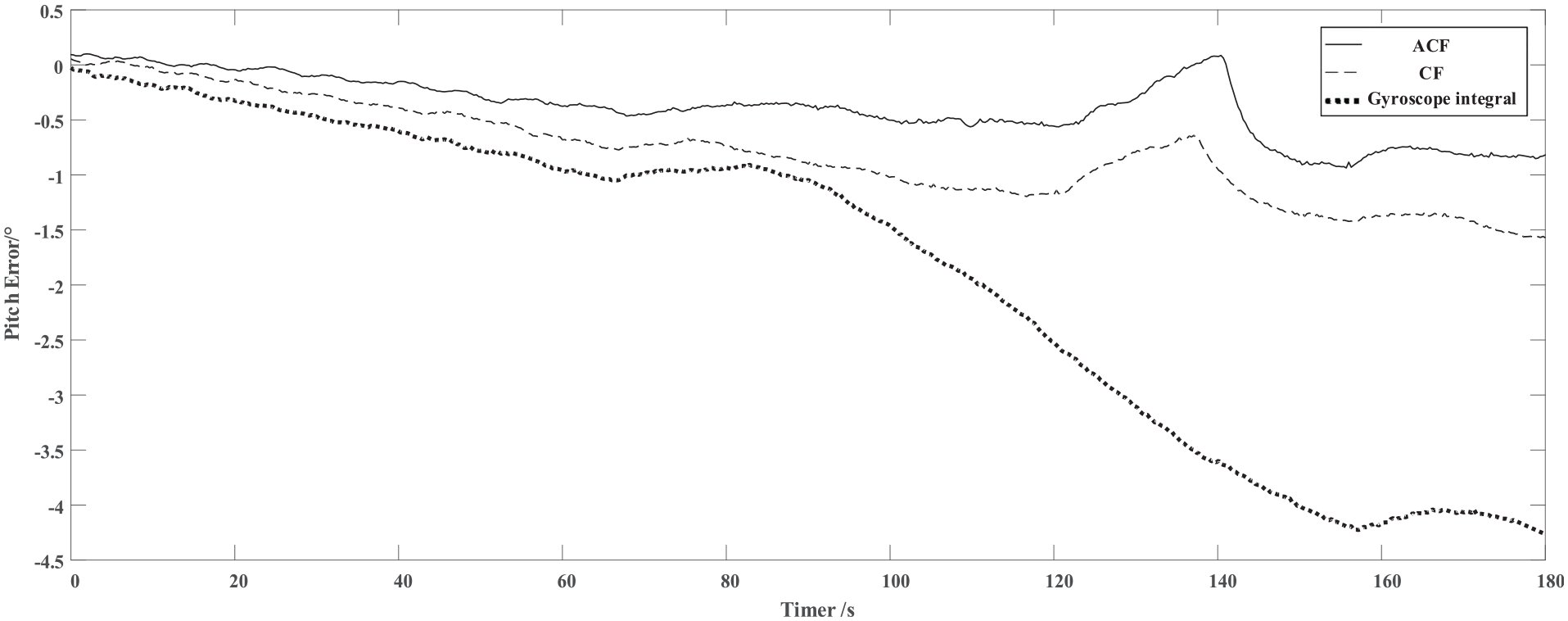
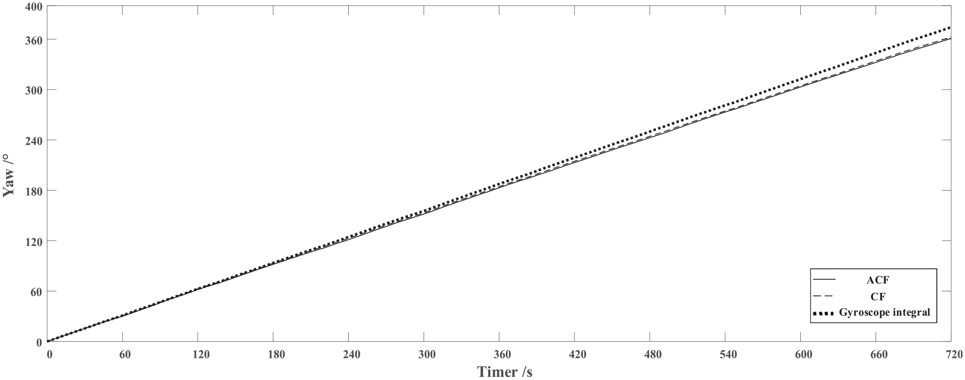
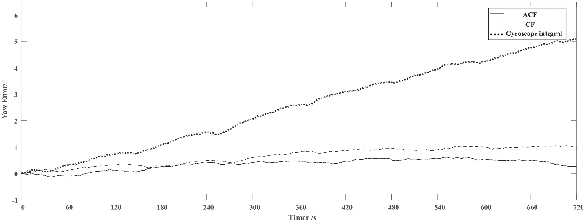
In the case of fast attitude change, the roll angle solution data and the solution error under the three algorithms are shown in Figures 16 and 17, respectively; the pitch angle direction solution data and the solution error are shown in Figures 18 and 19, respectively; the yaw angle direction solution data and the solution error are shown in Figures 20 and 21, respectively.
Roll angle estimation data under fast attitude change.
Roll angle estimation error under fast attitude change.
Pitch angle estimation data under fast attitude change.
Pitch angle estimation error under fast attitude change.
Yaw angle estimation data under fast attitude change.
Yaw angle estimation error under fast attitude change.
From Table 5, it can be observed that the mean value of solution error of adaptive complementary filter in roll, pitch and yaw direction is 0.152°, 0.102°, and 0.170°, and the error standard deviation is 0.172°, 0.084°, and 0.161°, respectively, which are smaller than the other two algorithms. It can be seen from Figures 17, 19 and 21 that there is no attitude drift in the three algorithms, and the traditional complementary filtering scheme is the worst.
Comparing the experimental results in static and dynamic conditions, we can get the following conclusion:
(1) Gyroscope shows better dynamic performance, which could provide a relatively accurate attitude angle estimation when the system rotates at a high speed (the attitude changes quickly), but suffers a lot from the drift when the system is in static or low rotation speed (the attitude changes slowly), which may lead to the error accumulation and the measurement result deviating quickly from the actual attitude angle of the measured object.
(2) Traditional complementary filter can only meet the accuracy of the solution in one state due to the fixed filter coefficients. As in this paper, the traditional complementary filter can only guarantee better solution effect in the case of static or low speed rotation (the attitude changes slower), while the solution effect is the worst when the system rotates at high speed (the attitude changes faster);
(3) The adaptive complementary filter can adjust the PI controller coefficients adaptively regardless of the low speed or high speed rotation of the system, so that the filter has the best solution effect in different rotation states.
Interference experiment
The interference experiment is divided into two parts: the magnetic interference experiment and the motion acceleration interference experiment. The former is used to test the precision variation of the adaptive algorithm under the external magnetic field interference, and the latter is aimed to test the precision variation of the adaptive algorithm under the motion acceleration interference.
Magnetic interference experiment
The mean, standard deviation and maximum values of the yaw direction attitude angle error calculated by adaptive complementary filter and traditional complementary filter in the case of external magnetic field interference, which is simulated by setting the sensor in static position and approaching it with a magnet, and then moving the magnet away, are listed in Table 6. The solution data of the adaptive complementary filter and the traditional complementary filter are shown in Figure 21.
Estimation error table of yaw angle under magnetic interference.
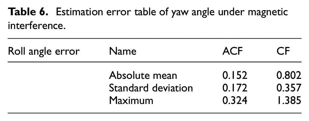
As showed in Table 6 and Figure 22, the sensor is disturbed by a magnet at the point A, and the magnet leaves at the point B. The yaw angle calculated by the traditional complementary filter produces a large error of about 38° under magnetic interference, while the adaptive complementary filter has a maximum error of 0.248° and an average error of 0.141° in the case of magnetic field interference. It is proved that the adaptive complementary filter can effectively deal with the external magnetic field interference, and the solution effect is obviously better than the traditional algorithm.
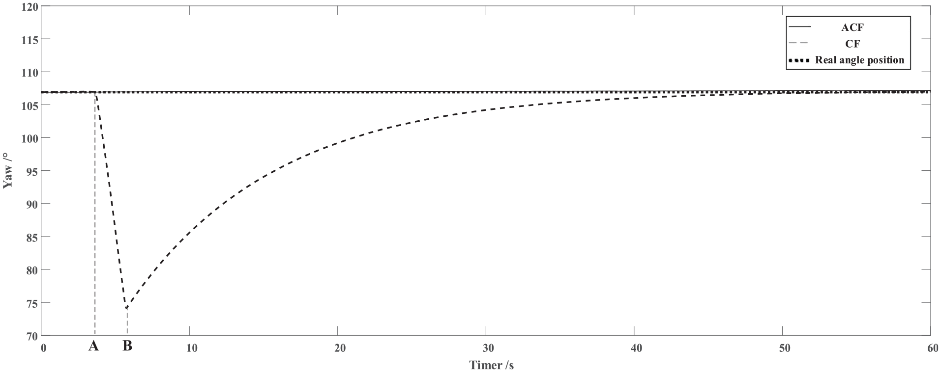
Yaw angle estimation data under magnetic interference.
Acceleration interference experiment
In this section, a linear variable speed guide is built and its specific composition is shown in Figure 23.
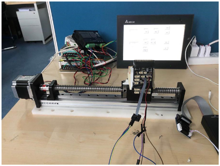
Linear variable speed guide.
The sensor is fix on the guide slide with a certain attitude. As the motor rotating nonuniformly, the guide rail slider is driven to move in a variable speed and possess a motion acceleration, which is made to simulate the case of aircrafts interacting with the external environment during the their flight.
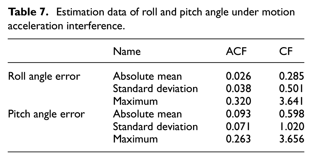
The mean, standard deviation, maximum values of the roll, pitch direction attitude angle errors calculated by adaptive complementary filter and traditional complementary filter in the case of motion acceleration interference are listed in Table 7. And the roll and pitch angle data of adaptive complementary filter and traditional complementary filter in the case of motion acceleration interference are showed in Figures 24 and 25 respectively.
Estimation data of roll and pitch angle under motion acceleration interference.
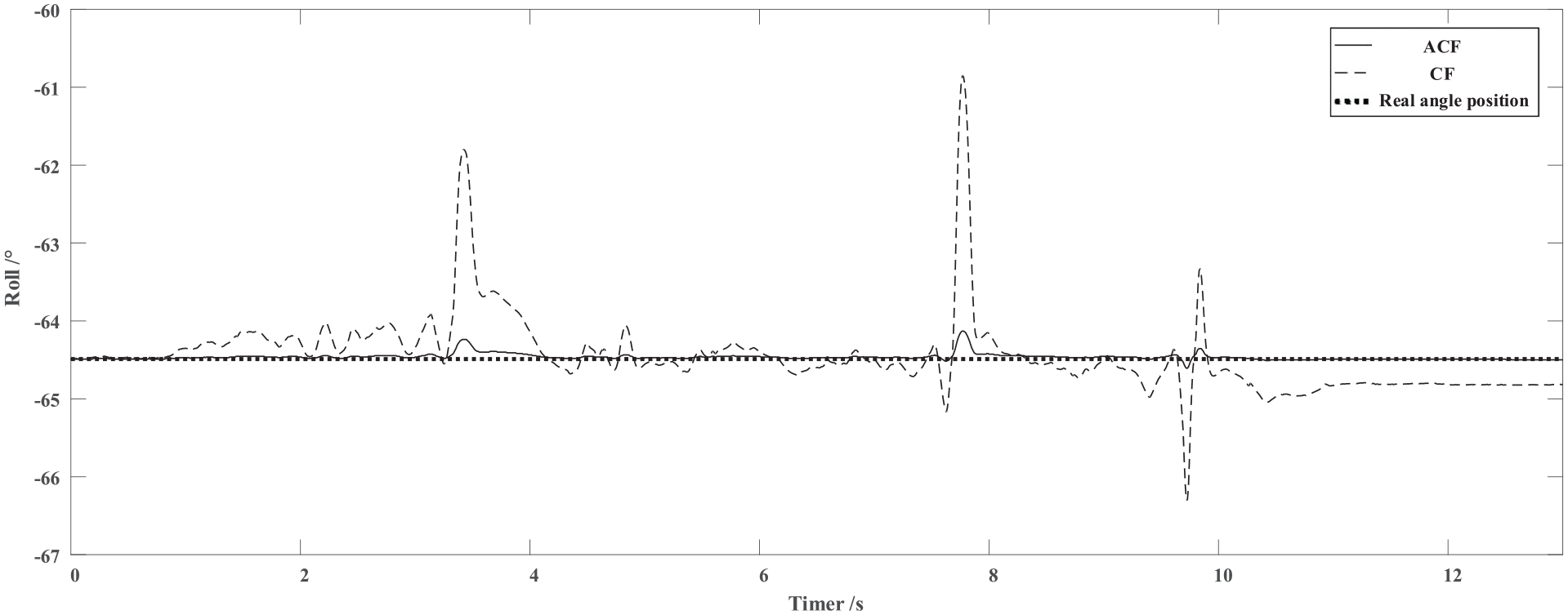
Roll angle estimation data under motion acceleration interference.
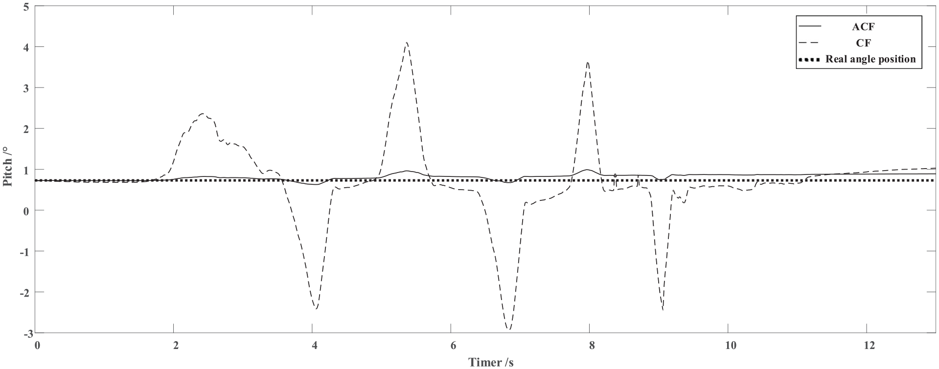
Pitch angle estimation data under motion acceleration interference.
Through Table 7 and Figures 24 and 25, it can be obtained that the roll and pitch angles calculated by the traditional complementary filter have a large error, in which the maximum error of roll angle is 3.641°, and the maximum error of pitch angle is 3.656°. While the maximum error of roll angle calculated by adaptive complementary filter is 0.320°, the average error is 0.026°, and the maximum error of pitch angle is 0.263°, and the average error is 0.093°. It is proved that the adaptive complementary filter can effectively deal with the motion acceleration interference, and the solution effect is obviously better than the traditional algorithm.
Conclusions
In order to solve the influence of environment disturbance and flight state on AHRS accuracy and reliability, an adaptive estimation scheme in which the weight and parameters of the compensation filter varying with the sensor norm is proposed in this paper. Firstly, the correction model of gyroscope is established. Secondly the adaptive adjustment rules of magnetometer and accelerometer weight are designed according to magnetic field norm and acceleration norm. Finally the fuzzy adaptive tuning rules of filter parameters are designed according to the motion state of aircraft and system deviation. So that AHRS can obtain accurate and reliable UAV attitude under different flight states, magnetic field interference and acceleration interference.
To verify the effectiveness of this scheme, AHRS test platform is designed and static, dynamic and interference experiments are carried out. The experimental results show that the scheme has high accuracy under all flight dynamic conditions. The scheme gave on accuracy of better than 0.280 in roll, 0.392 in pitch and 0.361 in yaw. Meanwhile, the proposed scheme is robust to both motion acceleration interference and magnetic field interference. The maximum estimation errors of roll angle, pitch angle and yaw angle are 0.320°, 0.263°, and 0.248°, respectively. All of the results demonstrate that the proposed algorithm can well provide a theoretical basis for improving the accuracy and reliability of UAV AHRS.
Footnotes
Declaration of conflicting interests
The author(s) declared no potential conflicts of interest with respect to the research, authorship, and/or publication of this article.
Funding
The author(s) disclosed receipt of the following financial support for the research, authorship, and/or publication of this article: This work was supported by Research on Key Technologies of air ground cooperation of UAV with land combat platform (NO. LJ20191A0512245).
Data availability statement
Data sharing not applicable to this article as no datasets.