
Abstract
A pair of tile-shaped transmitting and receiving coils, which is suitable for wireless power transfer system of autonomous underwater vehicle (AUV), is proposed in this paper. Both coils are designed as the tile shape to fit the AUV’s outer shell. And the transmitting coil which is located on the dock is a little larger than the receiving coil that is embedded in the UAV. With the HFSS software, the proposed coil shape was optimized. The performance of the coils was analyzed. By adjusting the coil offset distance and angle. the positioning relationship between the two coils was optimized. A serial-serial compensation topology was established, and an appropriate capacitor was selected to construct the WPT system. The experimental results verified the correctness of the theoretical analysis. The output power reached 30 W and the transmission efficiency reached 68.5%.
Introduction
With the rapid development of marine science and technology in recent years, there is an increasing demand for underwater vehicles charging technology. Traditional underwater vehicles rely on power supply methods such as wet-plug waterproof connectors and the replacement of energy storage devices.1–4 However, the conventional wet-plug power supply approach risks of short circuits caused by metal contacts and frictional losses during plug insertion and removal, limiting the operational capabilities of underwater vehicles. 5 Wireless power transfer (WPT) systems has demonstrated advantages in many fields, including underwater electrical equipment,6–9 industrial robots,10–13 implanted medical equipment,14–17 and electric vehicles,18–21 etc. And underwater WPT technology has become a new method for underwater power supply due to its advantages, such as non-contact energy transmission, high safety and reliability, and strong concealment. 22 In order to improve the stability of energy transmission, optimization of the coil shape is necessary.
Due to the unique characteristics of the marine environment, underwater vehicles are inevitably subject to the influence of water currents, which dynamically affect the coupling between the transmitting coil and the receiving coil of the underwater vehicle.23,24 The receiving coil structure described in Zhang et al. 25 is composed of two counter-wound coils. The two coils can be completely decoupled while ensuring that the mutual inductance between the receiving coil and the transmitting coil remains constant within a certain range. It possesses the capability to prevent rotational misalignment. However, when constructing physical coils, it is difficult to obtain a set of circular magnetic sheets for coil winding. As a result, the coil structure can only be replaced by a rectangular magnetic core, which can lead to a certain degree of mutual inductance fluctuation and subsequently affects the ability to prevent rotational misalignment.
In this paper, a pair of tile-shaped transmitting and receiving coils suited for underwater vehicle is proposed and analyzed. The organizational structure of this paper is outlined as follows: the first chapter presents the design concept; the second chapter evaluates the theoretical influence of circuit structure and marine environment; the third chapter establishes the prototype of a new type of coil based on the principles and examines the impact of axial and radial offset on output efficiency in underwater environment simulations; the fourth chapter presents the design and experimental results of the proposed coil in marine environment; the fifth chapter presents the conclusion.
Theoretical analysis of WPT
Theoretical modeling analysis of WPT system
Figure 1 shows proposed a typical wireless charging mode for AUVs. The power transmission device is placed at the docking station. The receiving coil is embedded on the surface of the AUV. This configuration allows batteries of the AUV to be charged while AUV is docked. Furthermore, the coaxial alignment helps overcome rotational misalignment of the AUV. This paper provides a detailed analysis of the variations in current and voltage output waveform, the offset distance sensitivity, and the efficiency fluctuation when there is axial and radial offset.
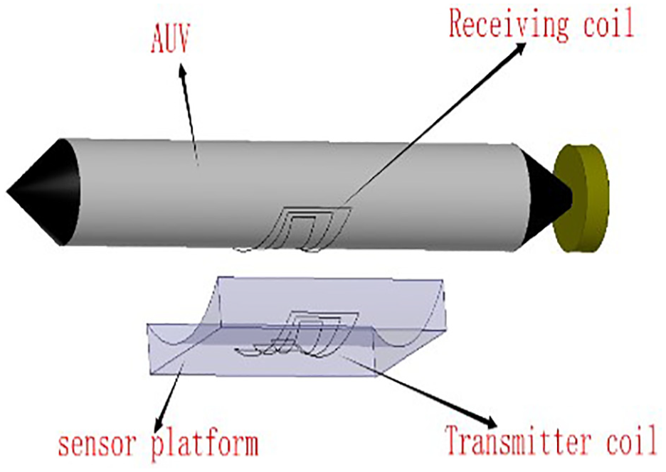
Typical wireless charging mode of AUV.
The proposed block diagram of the underwater WPT transmission system is shown in Figure 2, and the energy transmission system consists of a transmitting circuit and a receiving circuit. The transmitting circuit includes the primary side voltage input, high frequency inverter circuit and resonance compensation circuit, and the receiving circuit is composed of a resonance compensation circuit and a rectifier filter circuit.
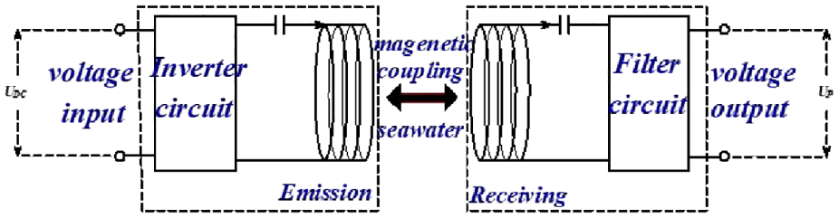
Basic structure of magnetic induction radio energy transmission.
Figure 3 shows a typical serial-serial (SS) topology, where UAB is the DC source,
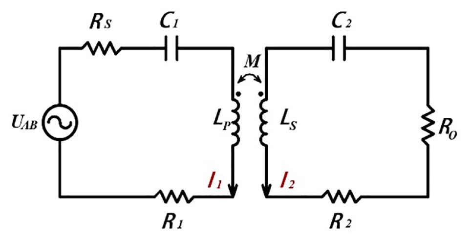
The serial-serial topology.
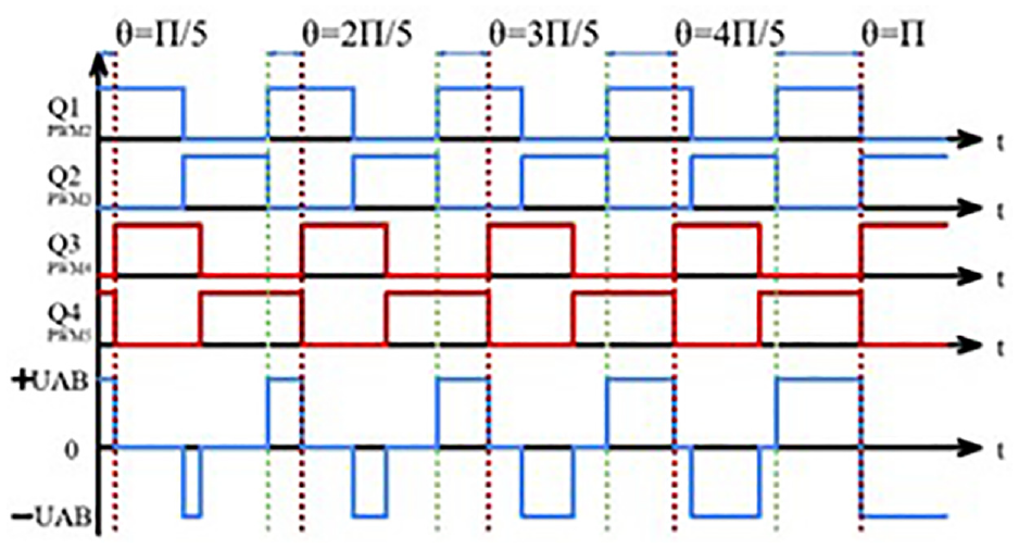
Phase shift control waveform diagram.
In order to ensure that the transceiver circuit operates in a resonant state (assuming that the resonant angular frequency is
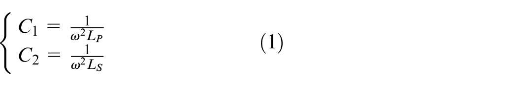
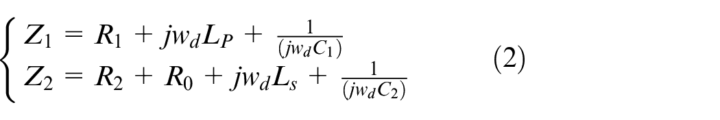
The equivalent impedance of resonant circuits at the transmitting end and the receiving end are named
The voltage of input high frequency AC signal is
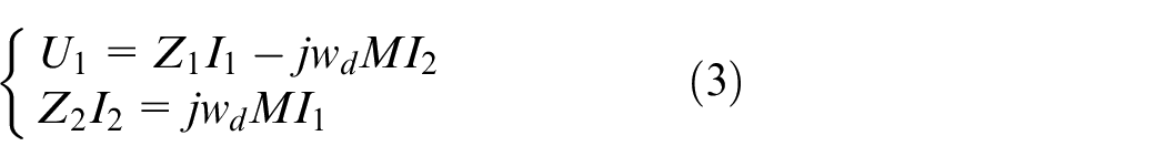
The transmitting coil current
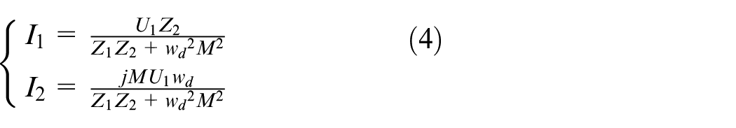
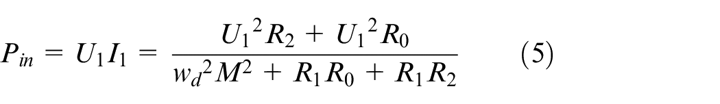
The input power
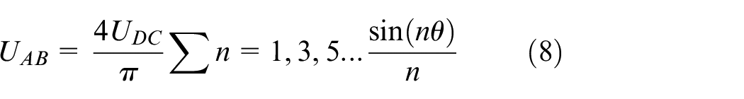
Using the phase-shifting full-bridge control strategy, Fourier Transform is performed on the output voltage of the full-bridge inverter. It can be obtained that when the phase shift angle is different, the effective values of each harmonic can be expressed as follow:
Assuming the input voltage is constant and only the fundamental wave is considered, As the phase shift angle
Figure 5 shows the relationship of output voltage, mutual inductance and phase shift angle. When θ does not change, the output voltage increases with the increase of mutual inductance. On the other hand, when the mutual inductance value maintain unchanged and θ varies in the range of 0–π, the larger the phase shift angle, the higher the output voltage.
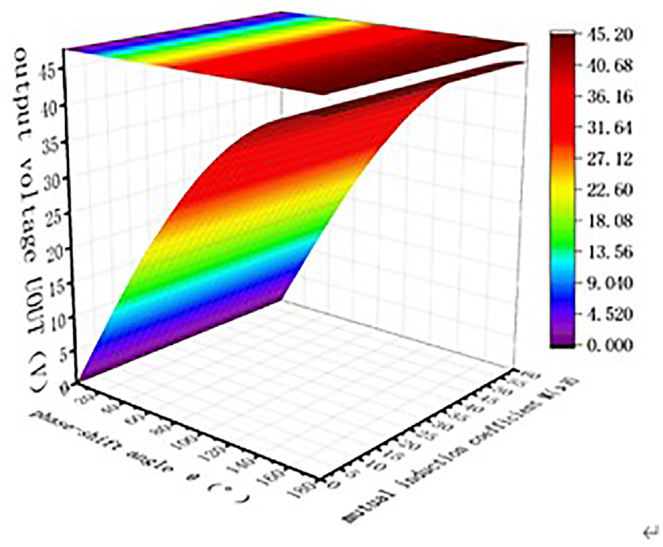
Output voltage and phase shift Angle and mutual inductance parameter.
Seawater medium transmission loss
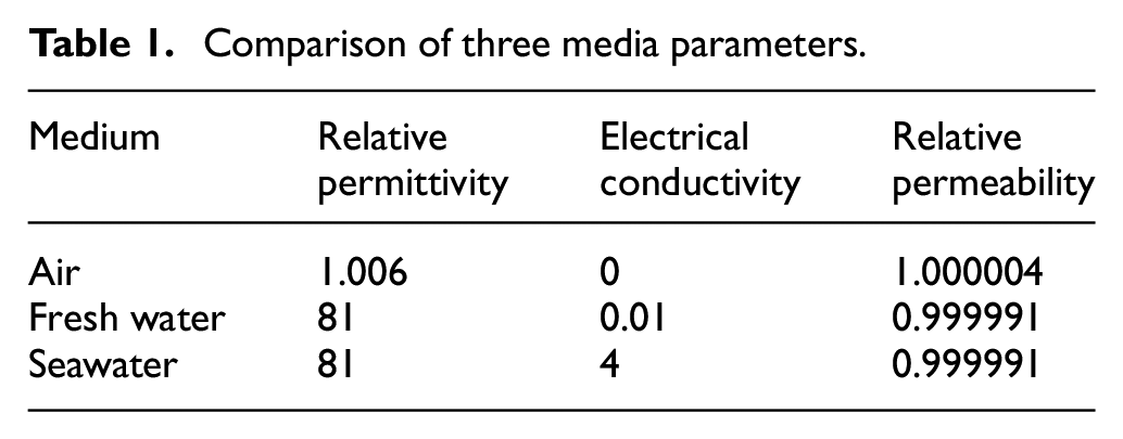
It is necessary to consider the characteristics of seawater in coil design since seawater differs greatly from freshwater and air in terms of dielectric constant and conductivity. Table 1 shows the parameters of the three media. The presence of conductivity in seawater can generate high-frequency eddy currents and cause eddy current losses, which affect the transmission efficiency of the magnetic coupling mechanism.26,27
Comparison of three media parameters.
Coil simulation and parameter optimization
The structure of the proposed transmitter-receiver coil is shown in Figure 6(a). In order to obtain the optimal relative position of the coils, the influence of axial, radial, and rotational offsets on transmission efficiency is investigated through HFSS simulation. Figure 6(b)–(d) shows the position of the transmitter and receiver coils that has radial, axial, and rotational offsets, respectively.
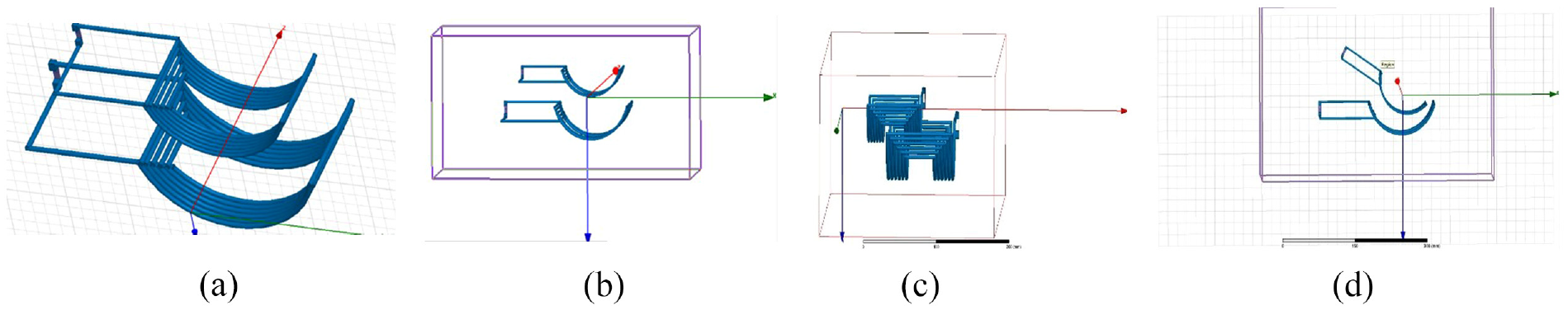
Simulation structure model: (a) aligned coil, (b) radial offset, (c) axial offset, and (d) rotation misalignment.
First, the coil model is designed in HFSS, and in the WPT system, the transmission distance is achieved by setting the seawater and air environment for simulation, and the TX coil and RX coil work at the kHz frequency. The relative position between the coil sections is set as follows: the distance between the transmitting coil and the receiving coil is 30 mm, the diameter of the transmitting coil is 72 mm, the receiving coil is reduced to 0.8 times the diameter of the transmitting coil according to the proportional XYZ axis, the coil material is copper, the wire diameter is set to 2 mm, and the simulation environment is set to sea water.
Figure 7 shows the effect of radial offset on transmission efficiency. It can be seen that as the distance between the two coils increases, the transmission efficiency firstly increases and then decreases. when the transmission distance is 30 mm, the efficiency reaches the maximum, so the optimal transmission distance of the two coils is set to 30 mm.
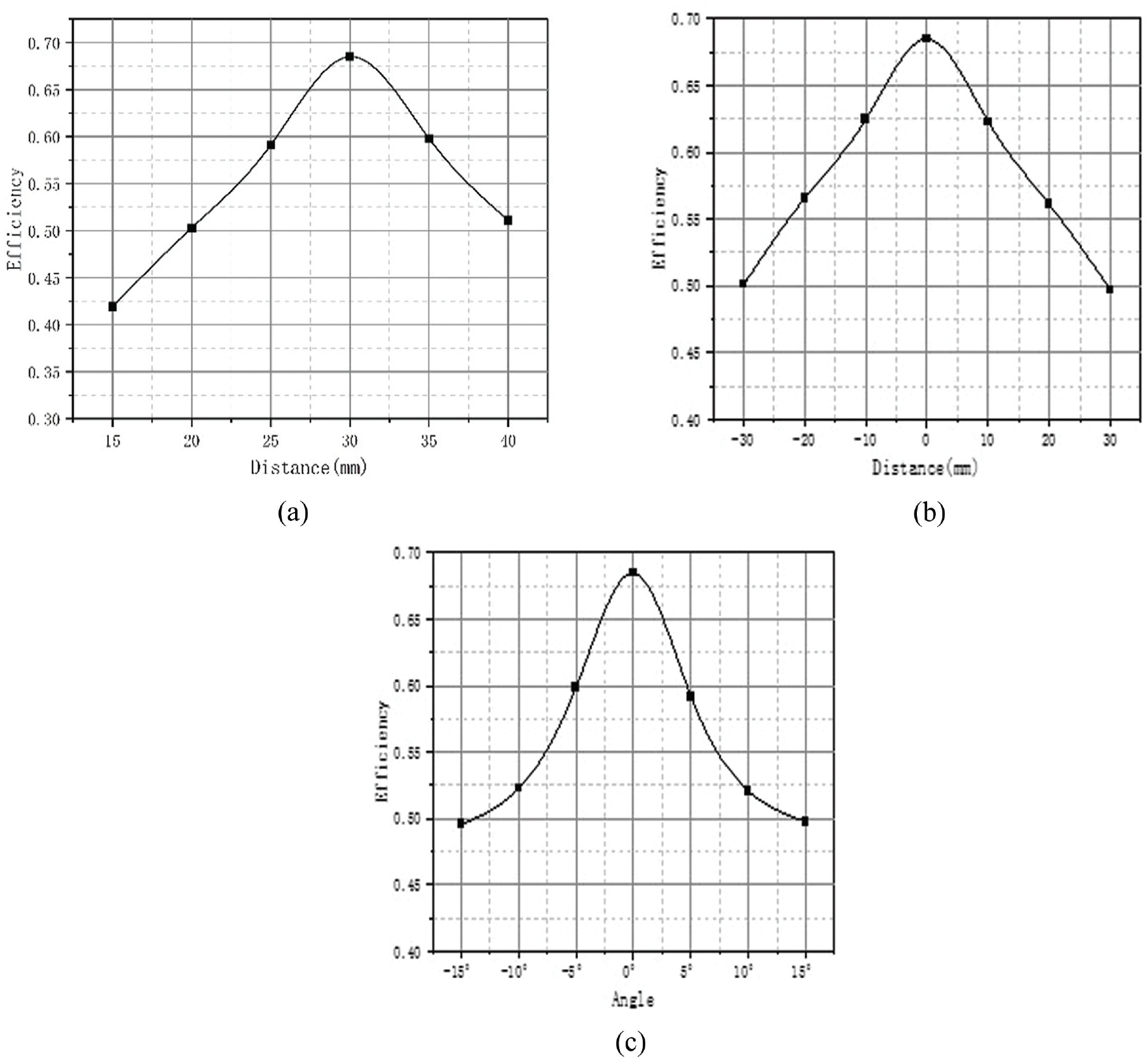
Efficiency variation with coil radial offset: (a) radial offset, (b) rotation offset, and (c) axial offset.
Figure 8 is a comparison of the transmission efficiency in seawater and air under different working frequency. There is a significant difference in the optimal operating frequency between air and seawater. Low-frequency is more suitable for wireless power transmission in seawater environment, while high-frequency is suitable for air. And in this design the working frequency in seawater is set to 30 kHz, which is the best operating frequency shown in the simulation results in seawater.
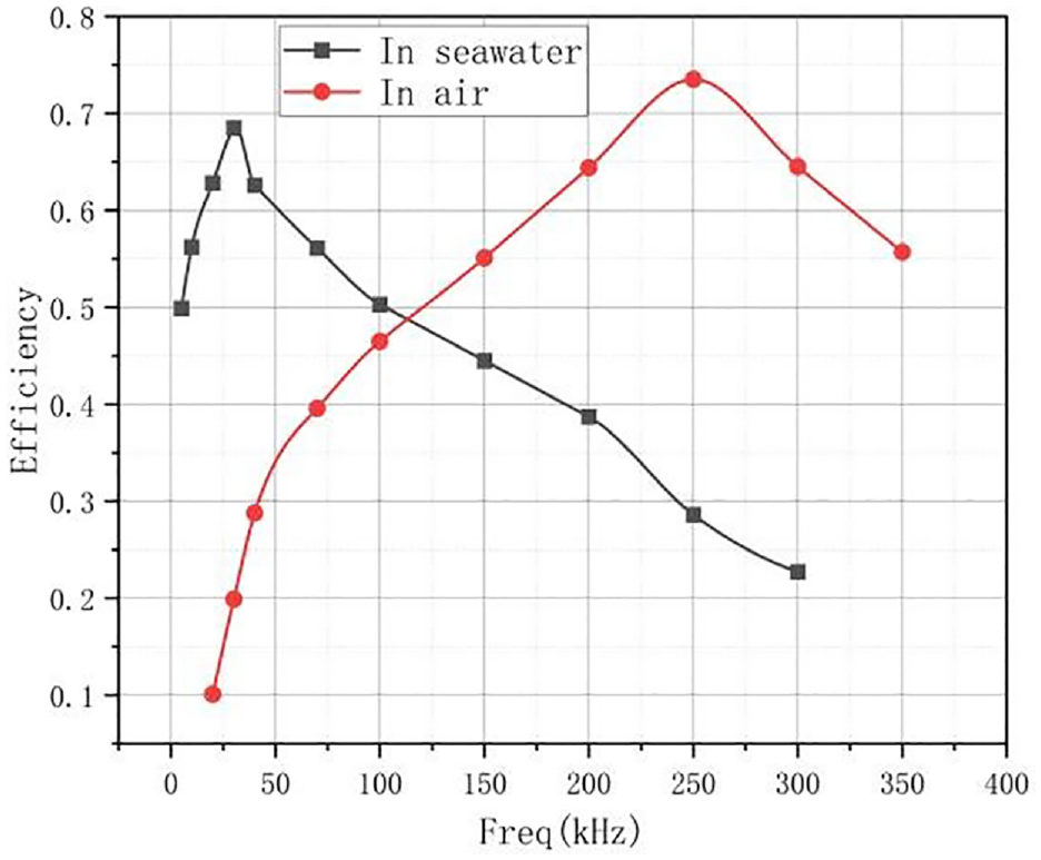
Frequency comparison in HFSS simulation under different environments.
Experimental analysis
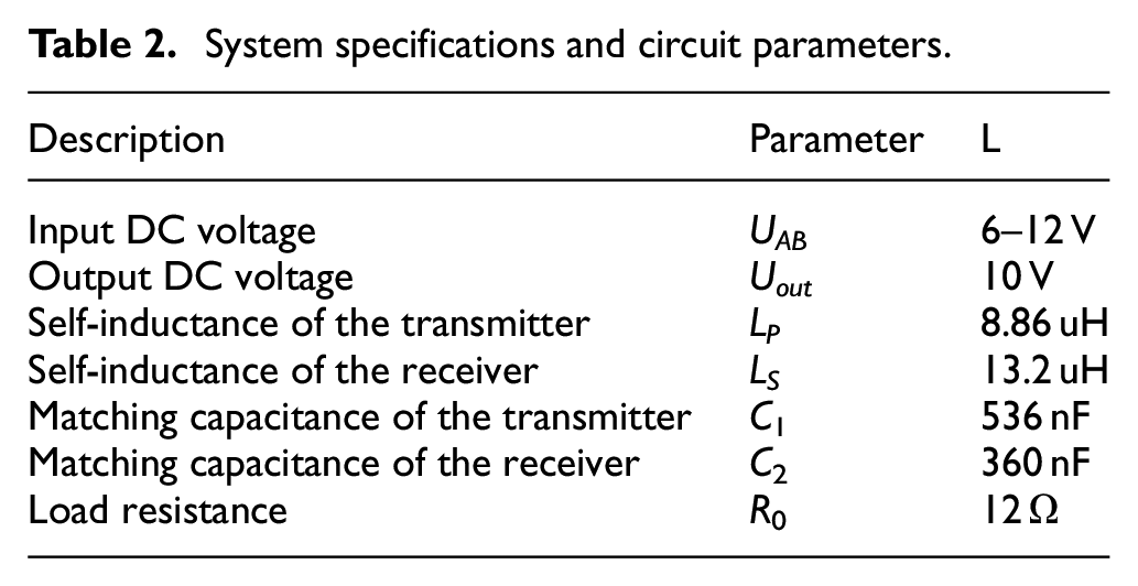
Based on the simulation of optimizing the coil shape, a set of actual coils was manufactured, using 500 strands × 0.1 mm of Litz wire to wrap the coils. Figure 9(a) is the photo of the transmitting coil and the receiving coil, while the Figure 9(b) shows the coils placed in saltwater for underwater experiments. The transmitting and receiving coils are made of 6-turn Litz wires, with a gap of 1mm between each turn. In the experiment, two tile-shaped structures with magnetic shielding plates were placed in a water tank. Ferrite thin film was used as the magnetic shielding material to reduce interference from surrounding magnetic fields, increasing the coupling between the two coils and thus enhancing the transmission efficiency. The thickness of the ferrite sheet is 0.05 mm, the relative magnetic permeability is 200. The physical circuitry parameters and system specifications is provided in Table 2.
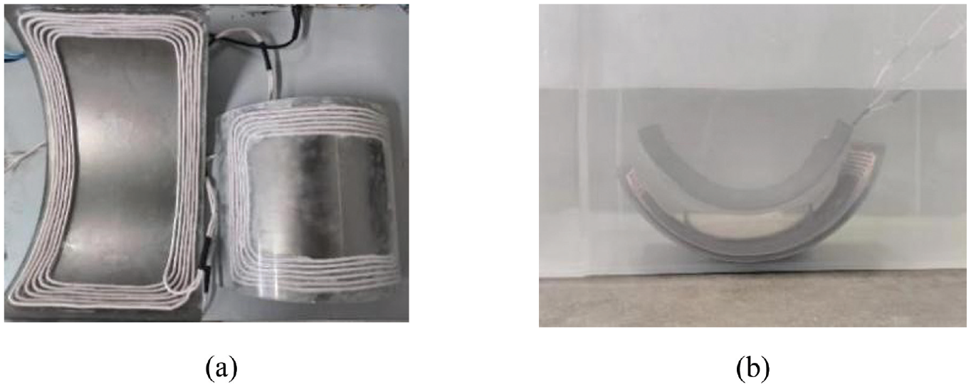
Experimental model: (a) underwater coil model and (b) coil model with magnetic shielding material added.
System specifications and circuit parameters.
The experiment investigates the effect of axial, radial and rotational offset by adjusting the position relationship between the receiving coil and the transmitting coil and verifies the feasibility of the simulation model.
The experiment results are all obtained by testing in saltwater environment with magnetic shielding plates. Figure 10 shows the waveform of the output voltage and current displayed on the oscilloscope. In detail, the yellow waveform is the output voltage, the blue waveform is the output current. The voltage and current in Figure 10(a) have the maximum value since it is tested under the optimal relative position. And the voltage, especially the current, is a little smaller than those in Figure 10(a), showing that the output power decreases under axial, radial, and rotational offset.
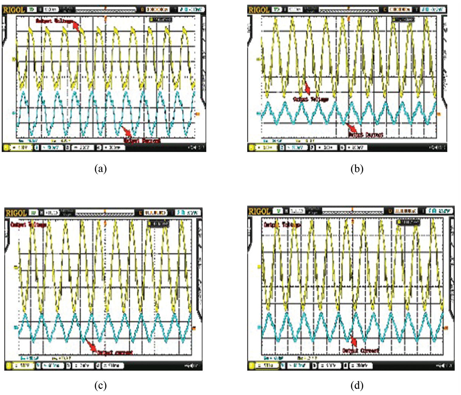
Underwater coil offset output voltage current waveform diagram: (a) underwater no offset, (b) rotation misalignment, (c) axial offset, and (d) radial offset.
Figure 11 shows the sensitivity of output power to offset when the coil is subjected to axial, radial, and rotational offsets. Figure 11(a) shows the rotation offset has a smaller impact on output power, and the output power is more stable within a small angle offset range, while the Figure 11(b) shows the radial offset has the greatest impact on output power. When the offset distance is 10mm, the output power decreases by about 16.7%. And the Figure 11(c) shows the sensitivity of axial offset to output power is less than that of radial offset.
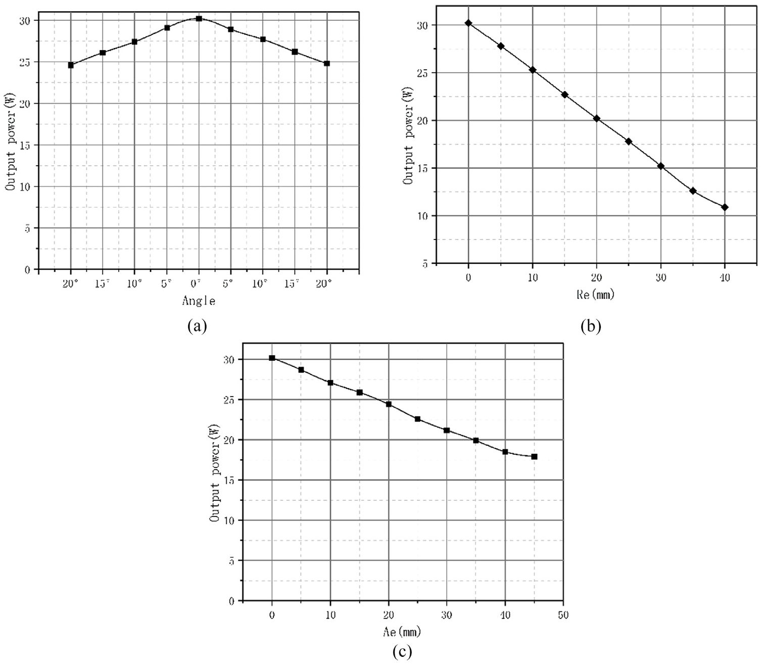
Output power versus offset curve: (a) rotation offset, (b) radial offset, and (c) axial offset.
Figure 12 shows the influence of increasing input voltage on output power and efficiency when the coil is subjected to no offset, axial, radial and rotational offsets. When the input voltage increases, both the output power and efficiency increase. Figure 12(a) shows that when the coil is no offset, the maximum output power and efficiency are achieved at input voltage of 12 V. The output power reaches approximately 30 W and efficiency reaches 68.5%. Under the axial, radial, and rotation offsets, the output power and efficiency are a little smaller than those in Figure 12(a).
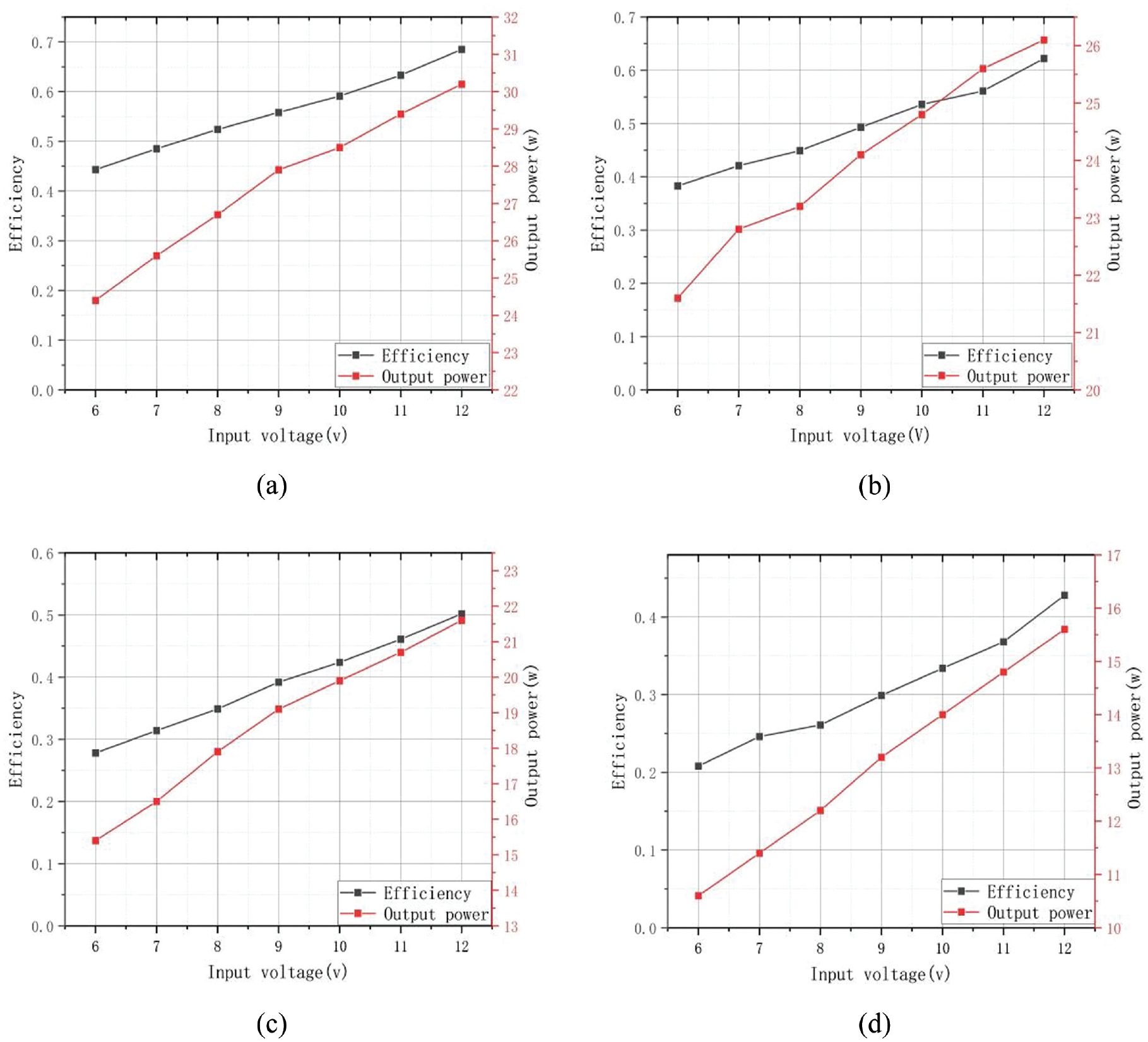
Efficiency under different offset conditions: (a) no offset, (b) rotation misalignment, (c) axial offset and (d) radial offset.
Conclusion
This article presents a tile-shaped coil adaptable to the shape of an underwater vehicle, which can be embedded in the main body of the underwater vehicle. The transmission coil is used as a charging station, effectively improving the charging efficiency through a strong central magnetic field. The performance of the coil is evaluated using HFSS. Experimental results verify the correctness of the theoretical analysis and simulation results, with an underwater efficiency of up to 68.5% under the optimal offset distance.
Footnotes
Declaration of conflicting interests
The author(s) declared no potential conflicts of interest with respect to the research, authorship, and/or publication of this article.
Funding
The author(s) received no financial support for the research, authorship, and/or publication of this article.
Data availability statement
The available data will be distributed to readers based on the request.