
Abstract
Reactive and active power vector control of induction generators (IG) are essential requirements for generating high-quality electricity from wind power. These control objectives are challenging and difficult to achieve when using traditional strategies based on estimating reactive/active power, hysteresis comparators, and proportional-integral (PI) regulators due to load variations, changes in the value of rotor resistance, etc. So, to achieve these control objectives, this paper proposes a novel technique for the rotor side converter of IG-based contra-rotating wind power (CRWP) systems. The control based on the neural synergetic-super-twisting controller (NSSTC) is designed to minimize IG power ripples and improve the quality of current. The characteristics of the NSSTC-based strategy are presented, evaluated, and compared to the traditional direct field-oriented command (DFOC) based on traditional PI controllers and other reference techniques from the literature, highlighting that the NSSTC-based strategy is simpler to apply and more robust and performant than others classical nonlinear strategies. Comparative simulations are carried out on both the designed DFOC-NSSTC strategy and the DFOC technique to demonstrate the performance (good quality output power, low total harmonic distortion (THD) value of rotor currents, short response time and high robustness) and advantages of the suggested nonlinear technique.
Keywords
Introduction
Electrical energy is one of the most prominent energies in the current era because of its characteristics and ease of production compared to other energies. This energy is easy to transport and inexpensive, as it can use overhead or ground lines. This energy can be generated using known sources such as gas and coal, as the use of these sources causes several unwanted problems such as the spread of toxic gases and global warming. Moreover, the use of these traditional sources makes the production and consumption of electrical energy very expensive and inconvenient for state governments. Therefore, governments resorted to searching for appropriate solutions in order to obtain this energy by launching several research projects at the university and Laboratory levels. It is among the solutions that have been well received by all countries, and this is evident through the Tokyo Treaty of 1997, where several countries and governments committed to dispensing with the use of traditional sources such as petroleum in order to generate electrical energy and resorting to other free sources. The latter are represented by natural sources such as wind and sun energy, as the use of these sources greatly helps to protect the environment and reduce the phenomenon of global warming. Using natural sources to generate electrical energy will significantly reduce the bill for production and consumption of electrical energy. Wind energy (WE) is one of the most prominent of these renewable sources that has gained great popularity for power generation, as turbines called wind turbines are used for the purpose of converting WE into mechanical energy. The latter is converted by generators into electrical energy.
In the field of electrical machines, there are several generators that can be used in the field of renewable energy, such as asynchronous generators, direct current generators, and synchronous generators. These generators differ in terms of durability, maintenance, cost, control, and performance.
The induction generator (IG) has been widely used in WE systems for its low maintenance, high efficiency, and simplicity. 1 The IG can be easily controlled compared to other generators, as it can use several linear or non-linear techniques. Moreover, the use of the IG in the WE system makes the system more durable and reduces periodic maintenance due to its durability. The advantage of using this generator lies in connecting the stator of the generator directly to the network without the need to use an inverter or any other intermediary, which makes the system simpler and less expensive. In addition, the speed of the generator can be controlled by feeding the rotor part of the machine, which gives it an advantage that is not found in other machines. In this generator, the active power (Ps) ripples can be easily generated due to both lookup table (LT)and two hysteresis comparators (HCs). 2 The IG uses two converters (rotor side converter (RSC) and grid side converter (GSC)) and most IG control techniques uses a classical strategy such as field-oriented command (FOC) to regulate the reactive power (Qs) and Ps. Thus, the Qs/Ps can be easily controlled using traditional proportional-integral (PI) controllers, but the ripples of the Ps and Qs are inherently generated. 3 The FOC strategy relies on estimating capabilities, which makes it affected by changing machine parameters, which is undesirable. This strategy has been applied to several electrical machines such as induction machine, 4 asynchronous generator, 5 synchronous motor, 6 synchronous generator, 7 Brushless DC motor, 8 and interior permanent magnet synchronous machines (PMSMs). 9 This strategy has two types: the direct FOC (DFOC) strategy and the indirect FOC (IFOC) strategy, where the difference between them lies in complexity, durability, performance, ease of implementation, and ease of application on electrical machines. The difference between the two strategies lies in the number of controls used. In the DFOC strategy, two PI controllers are used, and in the IFOC strategy, four PI controllers are used, which makes the IFOC strategy more complex and contains a significant number of gains, and therefore it is difficult to adjust the dynamic response easily, as is the case. But the IFOC strategy provides better results and distinctive performance compared to the direct strategy. In Amrane et al., 10 the FOC technique is one of the most widely used commands for controlling IG due to its ease of implementation and simplicity. This strategy depends on the mathematical model of the system, which makes it affected in the event of a malfunction. In addition to the use of power estimation and the PI controller in order to control the quantities, it has a distinctive feature that makes it one of the least concerned strategies for use in the field of control due to the presence of other strategies that are more performant and robustness. However, this command has several problems such as torque and Ps ripples. Also, the FOC strategy gives a current that has a very large total harmonic distortion (THD), which is not desirable. As it is known, high ripples in the current affect the system’s yield and life span, which leads to a high maintenance cost.
There are several recently published works on how to improve the characteristics and advantages of the FOC technique of IG-based WE systems. Among these techniques, we find artificial intelligence (Fuzzy logic (FL), neural networks (NNs), genetic algorithms (GAs), and neuro-fuzzy(NF) algorithms) and nonlinear techniques (super-twisting algorithm (STA), sliding mode command (SMC), and synergetic control (SC)). In Khan et al., 11 the NN techniques are used to ameliorate the efficiency of the FOC technique, and to improve the quality of the power produced by the IG integrated into WE. In this work, the author used NN techniques to overcome the problems of the FOC strategy, where all PI controllers are replaced by a neural controller. In addition, the strategy pulse width modulation (PWM) was relied upon to control the RSC. The proposed strategy uses the same estimation equations used in the traditional strategy. The negative of this proposed strategy is that it is related to the mathematical model of the system, which makes it affected if the values of the system parameters are changed, which is an undesirable matter that causes a decrease in the quality of the current and an increase in energy ripples. Matlab software was used to implement and validate the proposed strategy with a comparative study of the traditional strategy. The simulation results showed the robustness of the suggested technique when a fault occurred, as well as in reducing the THD value of the current. Moreover, it is observed that the power ripples increased and the current quality also decreased in the durability test, which is undesirable. This increase was significantly noticeable in the proposed strategy, which makes searching for another strategy with greater performance and ability to overcome the problems of the FOC strategy, especially in the event of a malfunction in the machine. Another technique was designed in Amrane and Chaiba 12 to ameliorate the characteristic of the FOC technique based on the combination of FL technique and NN technique, where the traditional PI controllers are tuned by NF algorithms. In this proposed strategy, NF-type controls are used to control the distinct amounts. In addition to using the PWM strategy to generate control pulses in the inverter. Using an NF controller increases the robustness of the FOC strategy and reduces power ripples and the THD of current. The proposed strategy based on NF uses the same power estimation equations used in the traditional strategy, which makes it affected, which is undesirable. By observing the results obtained in this work, this proposed strategy reduced the THD rate by about 70% compared to the traditional strategy, and this value is very acceptable. This indicates the characteristics of the suggested technique in improving the properties of the FOC strategy. However, it is noted that in the case of the robustness test, the percentages of reduction in the THD value compared to the traditional strategy has decreased, as it is also observed that the energy ripples have increased, which makes us say that this strategy is not the optimal solution that can be relied upon in the field of control. In addition, the use of the NF strategy depends greatly on experience, as there are several solutions and all of them give results, which makes it difficult to choose the best and appropriate solution. In addition to the number of rules that can be used to implement the NF strategy, all of these factors do not help in obtaining good results. In Robyns et al., 13 a novel FOC technique was designed based on the FL strategy to command the induction machine drive. The strategy proposed in this work is a change to the traditional strategy, where all traditional controllers are replaced by FL controllers. To control the inverter, the PWM strategy was relied upon. The proposed strategy depends largely on experience, as there are no mathematical rules to facilitated the use of FL, which is not desirable. As is known, the greater the number of rules, the better the results. However, the system becomes slower and increases the difficulty of experimental implementation, which is undesirable. This proposed strategy was implemented in the Matlab environment under different working conditions, comparing the efficiency and performance with the traditional strategy. The suggested technique is robust and improves the performances of the induction machine compared to the conventional FOC technique. The simulation results show that the quality of the current and torque ripples is better if the proposed strategy is used in all the tests used. Despite these results obtained, this strategy has a negative, which is represented by its complexity and the presence of a significant number of gains, making it difficult to tune the control for good dynamic response.
In the field of control, combining strategies has been used as a suitable and best solution for controlling electrical machines and improving the characteristics of the strategies. It is possible to use a combination of two different strategies in order to exploit the advantages of both and compensate or even eliminate their potential disadvantages. For example, a combination between neural networks and backstepping control, or similar ones, for example, a combination between synergetic control and SMC. The use of fusion significantly improves the system characteristics, as it is considered an effective solution to overcome the disadvantages of the FOC strategy. In Djilali et al., 14 the FOC technique was suggested based on the neural SMC approach to improve the quality of the power and current of the IG-based WE system. The goal of the suggested FOC technique in Djilali et al. 14 minimizes the current, torque, and Ps/Qs ripples. This proposed strategy is different from the traditional strategy, as it is characterized by high robustness and outstanding performance as a result of the use of the neural SMC controller. In this proposed strategy, the PWM strategy was used to control the inverter. In this strategy, there are a significant number of gains and it is based on the mathematical model of the machine, which makes it more susceptible if the machine’s parameters change. This strategy was implemented using the Matlab environment, and the obtained results were compared with the traditional strategy. The obtained simulation results demonstrate the high performance and robustness of the proposed strategy compared to the traditional strategy. Despite the results obtained, current and torque ripples remain, which is undesirable. In Benbouhenni and Bizon, 15 a direct FOC technique was designed based on terminal SC technique theory with a constant switching frequency, where direct and quadrature rotor voltages were calculated based on terminal SC technique theory. The proposed strategy is a traditional strategy with the removed of traditional controls and replacing them with terminal SC technique. The proposed strategy is characterized by simplicity, ease of implementation, low cost, and few gains, which makes it easy to adjust and change. Durability and outstanding performance are among the most prominent features of this proposed strategy compared to the traditional strategy. This proposed strategy uses capacity estimation, as the same equations found in the traditional strategy are used. The negative of the proposed strategy is its reliance on the mathematical model of the system, which is undesirable, as it causes several problems and defects in the event of a malfunction in the system. Matlab software was used to implement this strategy on a 1.5 MW IG-based multi-rotor wind turbine system. In addition, a variable wind speed was used to study the behavior and characteristics of the proposed strategy. The results obtained in all the listed tests show the superiority of the proposed strategy in improving the quality of current and power. In addition to overcoming the shortcomings of the traditional strategy and greatly increasing the robustness of the system. Another robust strategy was used in Djilali et al. 16 to ameliorate the characteristics of the FOC technique as well as minimize the THD of the output current from IG-based WE system. This robust strategy is called the STA technique. This controller is simple and reduces the chattering phenomenon compared to the SMC approach. In this strategy, the STA controller is used to control the characteristic amounts. In addition to using the PWM strategy to generate the pulses necessary to operate the inverter. The proposed strategy is characterized by its robustness and outstanding performance, with a fast dynamic response. This proposed strategy relies on the estimation process in order to calculate the error in the characteristic quantities, which makes it affected if the machine parameters change, which is undesirable. Being affected by changing parameters makes the power quality decrease, and this causes several problems in the network. The command proposed in 16 has also been used in Listwan 17 to control a six-phase induction motor. In this experimental work, the STA controller was relied upon in order to overcome the shortcomings of the FOC strategy due to simplicity, low cost, and ease of implementation compared to several other controllers present in the field of control. The experimental results showed an improvement in machine performance compared to the traditional technique. Despite the results presented by the proposed strategy compared to the traditional strategy, the problem of current and torque ripples remains as a result of using flux and torque estimation. In addition, the proposed strategy depends on the mathematical model of the machine, which causes ripples and decreased performance in the event of a malfunction. In Nicola and Nicola, 18 the FOC strategy was proposed based on SC technique and SMC controller of PMSM drives. The design is robust compared to the conventional FOC technique. The use of these nonlinear strategies increases the robustness and performance of the FOC strategy, as the need for PI controls is eliminated. Using these nonlinear strategies requires the use of both flow and torque estimation. To estimate these quantities, voltage and current must be measured, which requires the use of high-precision measuring devices to obtain the error value between the measured value and the reference value as little as possible. The Matlab environment was used to implement the proposed strategy, where the simulation results showed the superiority of the proposed strategy in terms of reducing torque ripples and reducing the value of THD of current compared to the traditional strategy. A new technique based on the FOC technique was suggested to regulate the torque and speed of the PMSM by using an SMC observer. 19 The use of SMC observer in order to overcome the disadvantages of the FOC strategy makes the system more complex and expensive. In addition to the presence of a significant number of gains, which makes it difficult to determine the appropriate values in order to obtain good results. The use of an SMC observer makes the FOC strategy linked to the mathematical model of the machine, which is undesirable, as it increases the value of ripples and the THD of current in the event of a malfunction in the machine. This technique minimized the current, flux and torque ripples compared to the conventional FOC technique. A novel high-order SMC strategy was designed to improve the performance of the DFOC technique, where the conventional PI regulators are replaced by third-order SMC techniques. 20 The latter is a new strategy that was proposed to overcome the shortcomings of the SMC strategy, as it does not use the mathematical model of the machine, which makes it easy to implement and use on electrical machines and complex systems. Moreover, it has a low gain, making it easy to adjust, and the dynamic response can be changed with ease. The suggested nonlinear FOC technique is more robust, easy to implement, and minimizes the THD ratios of rotor/stator current compared to the DFOC technique. In this proposed strategy, third-order SMC techniques were used along with the PWM technique for the purpose of controlling the RSC of 1.5 MW IG-based multi-rotor wind turbine system. The problem with the proposed strategy lies in the use of power estimation in addition to its reliance on the mathematical model of the machine, which makes it provide unsatisfactory results in the event of a malfunction in the machine. This proposed technique was verified using digital simulation and studying its behavior compared to that of the traditional technique. The simulation results showed the high performance of the proposed technique in the robustness test compared to the traditional technique, as the proposed technique was affected very little, unlike the traditional strategy, which was greatly affected by changing parameter values, and this appears through the large values of ripples and THD of current. In Habib et al., 21 the indirect FOC technique based on the STA technique (IFOC-STA) was designed using the NF-based PWM technique to control the IG-based WE system. This proposed strategy differs from the traditional strategy and several other strategies in terms of the degree of complexity, ease of implementation, durability, and ease of adjusting the dynamic response. The proposed strategy is characterized by a greater degree of complexity than the traditional strategy, which makes it expensive and difficult to implement, which is undesirable. This strategy was implemented in a Matlab environment using a 1.5 MW IG. The proposed IFOC-STA strategy has been suggested to further reduce the ripples in the flux, Ps/Qs, and current compared to the IFOC technique of the IG-based WP system. However, the IFOC-STA technique using NF-PWM technique is robust compared to the IFOC-PI and DFOC-PI techniques. As it is known, the FOC strategy has many advantages and disadvantages compared to other strategies such as direct power command (DPC) and direct torque command (DTC) techniques, where the FOC technique differs from the DPC and DTC techniques in terms of working principles, dynamic response, and simplicity. Table 1 represents a comparative study of the most commonly used strategies in the field of control. According to this table, despite its simplicity, the FOC technique provides unsatisfactory results compared to the DPC technique and DTC technique, especially when changing machine parameters. Among the downsides of the FOC technique is the slow dynamic response compared to both DPC and DTC techniques. As well as the high rate of ripples for the current, torque and powers. Also, this technique is greatly affected by changes in machine parameters and this is mainly due to the use of a PI controller.
A comparative study between the FOC with DTC and DPC techniques.
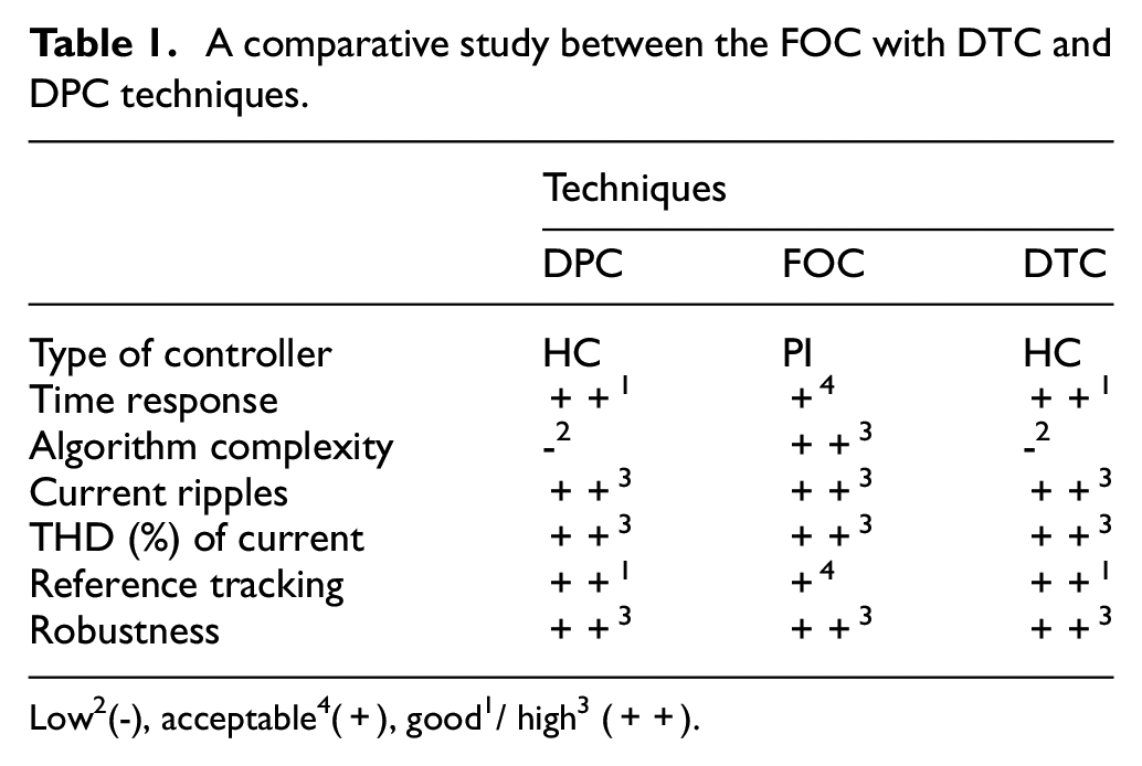
Low2(-), acceptable4(+), good1/ high3 (++).
On the other hand, SC technique and SMC approach were combined to improve the performance of the DFOC technique of the IG-based contra-rotating wind power (CRWP) system. 22 The proposed synergetic-SMC (SSM) approach is robust than the PI controller and SC technique. Also, the SSM technique is simple, being easy to implement, and more effective in minimizing the chattering phenomenon. The proposed strategy uses a synergetic-SMC technique to control the Ps and Qs, where the outputs of these controls are reference voltage values. These reference values are used by the PWM strategy to generate the control pulses necessary to operate the RSC of IG. In this strategy, the power estimation is used for the purpose of calculating the power error, and these errors are used as inputs to the synergetic-SMC controllers. This strategy was implemented in the Matlab environment using several different tests, with a study comparing the graphical and numerical results with the results of the traditional technique. The results obtained demonstrate the distinctive performance of the proposed technique compared to the traditional technique in terms of improving the characteristics and performance of the generation system. However, despite the results obtained, the problem of power ripples and low current quality remains present, which is undesirable.
To increase the durability of the WE system, increase the quality of the current and reduce the power ripples, several researchers have suggested using other techniques to command the IG, which is to combine techniques such as neural DTC control, 23 fuzzy DTC, 24 backstepping control, 25 neural SMC technique, 26 NF-SMC technique, 27 and SC technique. 28 Using these strategies obtained in the field of renewable energies leads to a significant increase in energy quality and a reduction in the value of THD of current. Some of these strategies are complex and difficult to implement, such as the NF-SMC technique, which is undesirable. One of the most prominent challenges facing generation systems is the control strategy, where a strategy must be used that is characterized by simplicity, ease of implementation, low cost, high performance, great durability, rapid dynamic response, fewer gains, and a great ability to improve the characteristics of the systems, especially in the event of a malfunction. All of these features are among the most prominent features that must be present in any control strategy. But it is difficult to find a strategy that has all of these features combined and can be relied upon in order to overcome the problems and defects of wind electrical energy generation systems.
One of the solutions that has been relied upon in the field of renewable energies, especially in wind energy, is the use of a combination of nonlinear strategies and artificial intelligence strategies, where the positives of these strategies are combined in order to increase durability and performance. As is known, artificial intelligence strategies are characterized by high accuracy and are not affected by changes in system parameters, which makes them among the most suitable solutions. Nonlinear strategies are famous for their high robustness and outstanding performance in reducing power ripples and increasing the quality of the current. In Benbouhenni, 29 the author combined NN techniques and a third-order SMC technique to further minimize the power ripples and improve the quality of the current produced by the IG-based CRWP systems. NN techniques were used to compensate for sign(u) in the third-order SMC technique controller, as the proposed controller maintains simplicity, ease of implementation, and increases the robustness of the system as a whole. NNs are characterized by robustness, accuracy, ease of application, and are not related to the mathematical model of the system, which makes the proposed controller not affected by changes in machine parameters and performs excellently in order to reduce energy ripples and increase the quality of the current. A CRWP system was used to obtain the torque needed to rotate the generator. Moreover, the PWM strategy was used to simplify the system, reduce the overall cost, and control the operation of the RSC. The proposed system was implemented in a Matlab environment using a 1.5 MW IG, where a variable wind speed was used for the purpose of studying the behavior of the proposed strategy. The results showed the effectiveness of the combination of NN techniques and third-order SMC strategy in improving the advantages and characteristics of the IG-based CRWP system. Despite the outstanding performance and high reduction rates for both power and current ripples, the problem of current/energy quality remains an issue, especially in the case of durability testing, where significant ripples are observed in both power, current, and torque. These ripples can be attributed to the power estimation, as this proposed strategy uses the power estimation process in order to calculate the power error. A fractional-order PI-STSMC technique (FOPI-STSMC) is used to improve the characteristics of the FOC technique of the IG. 30 In this work, a combination of three different strategies (fractional-order control, PI controller, STA technique) was used to obtain a new controller that is more durable and performant. This proposed controller is used to overcome the defects and problems of the traditional FOC technique. High performance and great durability are among the most prominent characteristics of this proposed controller. Using the FOPI-STSMC controller significantly improved the advantages of the FOC technique compared to using the PI controller. The proposed strategy was implemented in the Matlab environment with a graphical and numerical comparison with the traditional strategy. Several tests were used to complete this comparison and prove the efficiency and performance of the proposed strategy. In this study, two different wind speed profiles were used, with a 1.5 MW IG used to complete this study. The graphical and numerical results prove the superiority of the proposed strategy over the traditional strategy in terms of reducing energy and torque ripples. Also, the quality of the current is excellent when using a designed FOPI-STSMC technique and this is shown by the low value of the THD ratios, which is around 0.10%. Another robust strategy used in Benbouhenni et al. 31 to improve the current quality of an IG, the generator is controlled by the DFOC technique. The combination of PI controller and fractional calculus significantly improved the characteristics of DFOC technique and this is shown by very low ripples value compared to using the PI controller. The proposed strategy is a change and modification in the traditional technique, where the traditional controls were dispensed with and replaced with the proposed controls. In addition to using the PWM technique for the purpose of controlling the RSC of IG. The proposed technique maintains the simplicity and ease of implementation that characterized the traditional technique, while significantly increasing its durability. Moreover, the use of the fractional-order PI controllers improves the dynamic response of Ps and Qs compared to the PI controllers. A 1.5 MW generator was used to complete this study, and the Matlab environment was used for this purpose. The simulated results prove that the quality of current and power are high in the case of the proposed strategy compared to the traditional strategy. This proposed technique has the negative side of estimating the capabilities, which makes it related to the machine parameters, which is undesirable and causes ripples if the parameters change. A novel fault-tolerant FL technique tracking controller combined with a nominal command law is proposed in Abdelmalek et al. 32 to control the IG. The designed technique is robust compared to the conventional technique. Moreover, the use of Takagi-Sugeno Fuzzy PI-Observer improves the dynamic response and reduces the steady-state error (SSE) of Ps and Qs. This proposed strategy relies heavily on experience, as the use of FL makes control independent of the mathematical model of the system, which gives the possibility of obtaining distinctive performance and high durability. The negative of this strategy can be identified in FL itself, as there are no mathematical rules that help how to choose the rules in order to obtain good results. In addition to the presence of a significant number of gains, which makes it difficult to adjust the dynamic response. The proposed strategy was implemented using digital simulation, and the results obtained showed outstanding performance compared to the traditional strategy. DPC strategy and BC technique were combined to control the IG, 33 where the combination led to a more efficient technique and this is shown by the value of the ripples and the dynamic response of the Ps and Qs. In this proposed strategy, the LT and HC were eliminated and replaced with both the BC technique and the PWM technique. Compared to the DPC strategy, the proposed technique is characterized by complexity, difficulty of implementation, and the presence of a significant number of gains, which is undesirable. The use of the BC technique makes the proposed control linked to the mathematical model of the machine, and this creates several problems and drawbacks, especially if the machine parameters change. This proposed technique was implemented in Matlab environment with results compared with the traditional technique. Simulation results prove that energy ripples are less in the proposed technique compared to the traditional strategy. Also, the current quality is significantly improved compared to the FOC strategy. A combined FOC strategy and DPC technique are proposed for the RSC of the IG. 34 The proposed FOC-DPC technique enjoys the benefits of the FOC and DPC technique in a complicated control system. The characteristics of the FOC-DPC technique are compared with both the DPC and FOC techniques under SSE and transient conditions. This proposed technique differs from the DPC strategy in terms of simplicity, performance, durability, and ease of implementation. Moreover, using the FOC technique to improve the performance of DPC makes the proposed control related to the mathematical model of the machine, which is undesirable. Simulation results confirm the superiority of the designed FOC-DPC over either DPC or FOC strategies. The enhanced FOC technique is designed to control the IG using Matlab software. 35 In the enhanced FOC technique, FL technique is used to minimize current ripples and improve dynamic response. The proposed solution is based on the use of FL technique, where all traditional controllers are replaced by this strategy. The use of FL technique makes the FOC strategy not greatly affected by changes in the machine parameters. In addition to reducing energy ripples and increasing the quality of the current. The use of FL technique significantly increases the robustness of the FOC strategy and increases performance. But the negative of this strategy lies in the number of rules necessary to obtain good results, as this strategy depends on experience, which makes it difficult to find the number of necessary rules. Simulation results showed that the enhanced FOC technique is better than the FOC technique. In Djilali et al., 16 it was suggested to use the high-order SMC technique and first-order SMC technique to improve the effectiveness of the FOC technique of IG. The use of these nonlinear strategies makes the FOC strategy have distinctive performance. In addition to significantly increasing durability, which is desirable. However, the use of these nonlinear strategies creates an undesirable problem of chatter, as this problem causes an increase in the value of the energy ripples and a decrease in the quality of the current. The Matlab environment was used to implement the proposed strategies, and a comparative study was conducted between the high-order SMC technique and the first-order SMC technique to find out the best strategy that overcomes the disadvantages of the FOC strategy. The results showed that using the high-order SMC technique is the best solution to improve the advantages of the FOC technique for IG-based wind power. Also, the quality of the electrical current is higher in the case of the FOC strategy based on the high-order SMC technique. In Amrane et al., 36 the FOC technique based on the hysteresis current controller is suggested to control the IG. The designed FOC technique was compared to the FOC-PI technique, where the advantages and characteristics of the generator have been improved. This technique has both positives and negatives, as simplicity and ease of implementation are the most prominent features of this strategy. But this technique does not achieve the desired results, as energy ripples and current quality remain present, which makes the search for a technique with high performance, great durability, and has a great ability to overcome the problem of energy ripples. As is known, the greater the power of the generator, the greater the ripple value, which is undesirable. Dealing with a large power generator is not the same as dealing with a small power generator. In wind farms, large capacity generators are used and thus the problem of power ripples causes several problems in the network. Therefore, it is necessary to eliminate and overcome the problem of energy ripples, as the solution remains to search for a control strategy with distinctive performance and high efficiency. Through the works,29,31 there is a new turbine that was used to convert WE into mechanical power. The results of the studies carried out in Ayrir et al. 24 showed the performances of this turbine in improving the quality and capacity of energy production, where the energy generated by the CRWP is about 23% more than the energy produced by conventional turbines.
In this work, attention is paid to improving the advantages and performances of the DFOC technique because of its advantages such as simplicity and ease of implementation compared to both DPC and DTC techniques. Thus, a combination of three different techniques is designed to improve the advantages and reduce the disadvantages of the DFOC technique, where the NN techniques, STA technique, and SC technique are combined to obtain a robust technique.
In this work, an improved DFOC technique with low complexity is designed to minimize the ripples of the stator current and Ps and Qs. By investigating the inherent relationship between flux and current, the complicated current prediction is eliminated in the process of vector selection. Two kinds of DFOC techniques with modified space vector modulation (MSVM) technique are presented. The first one tries to reduce Ps ripples during one control period rather than nullifying the Ps error at the end of the command period. The second one eliminates the use of generator parameters and is very simple to implement, hence featuring strong robustness while minimizing Ps ripples. The proposed intelligent nonlinear DFOC technique achieves lower Ps and current undulations than traditional DFOC technique with halved sampling frequency. In fact, the harmonic distortion of the designed DFOC technique is even lower than that of the traditional DFOC strategy, especially in the variable-speed CRWP systems. The presented numerical simulation results confirm the superiority of the designed technique. To highlight the steps in implementing the proposed research idea, a diagram explaining the purpose of this paper is presented in Figure 1.
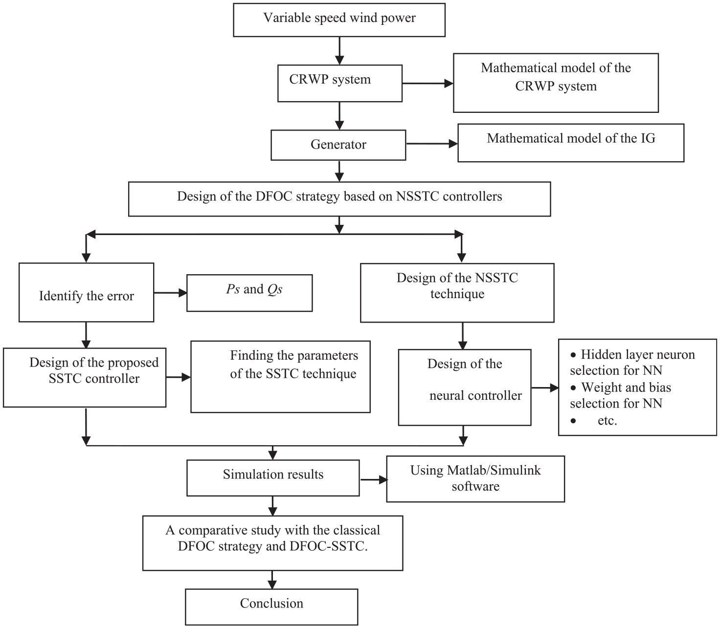
Diagram of research steps followed in this paper.
The main contribution of this work lies in the proposal of a more robust controller based on three different strategies, where the STA technique, SC technique, and NN algorithm were combined to obtain a neural synergetic-super-twisting controller (NSSTC). The proposed strategy mainly uses the same estimation equations proposed in the traditional strategy based on the synergetic-super-twisting controller (SSTC), but its performance is better than that of the strategies based on the PI control and the SSCT controller (except for the response time and setting in the case of the SSCT strategy).
The proposed controller does not require the mathematical form of the studied system and has low cost, and can be accomplished easily even if it integrates three strategies, as will be shown below. Also, it can be applied to complex systems such as the control of a seven-phase motor. On the other hand, there are several secondary objectives to be achieved in this article, which are as follows:
Reduction of Ps and Qs ripples influenced by the variation of IG parameters.
Minimization of the THD rate of the current IG-based CRWP system.
Improvement of Ps and Qs performances.
Conservation of the DFOC strategy characteristics.
Decrease the overshoot value for both active and reactive power.
Improving the response time of the power.
This paper is structured as follows. Section 2 presents the dynamic modeling of the CRWP system used in this paper. In section 3, the mathematical model of the proposed intelligent nonlinear controller (NSSTC technique) is presented. Section 4 briefly present the mathematical model of the DFOC technique of the IG-based CRWP system. Section 5 is focused on the suggested DFOC-NSSTC technique to command IG, where NSSTC controller is used to regulate the Ps and Qs. The results and the discussion of the IG control with three proposed controllers (PI, SSTC and NSSTC) to regulate the Qs and Ps are illustrated in Sections 6 and 7. Finally, Section 8 concludes the paper by presenting the main findings and future directions of research, as well as some comments and recommendations.
CRWP model
Figure 2 represents the suggested system based on wind energy using a new turbine known as a CRWP system. Among the basic components of this proposed system for study in this work are the IG, turbine, inverter, and filter, where the generator is the main element in the suggested system from the wind. The purpose of using the CRWP is to increase the mechanical power gained from the wind. This technology has been proposed or rather studied in several scientific researches.37–39 On the other hand, the IG system has been adopted in a large number of modern wind turbines because the topology has many advantages in terms of relatively high efficiency, small converter size, variable-speed operation, and four-quadrant Ps and Qs capabilities. 38 One of the generator systems currently commercially available in the WE market is the induction generator with the stator winding connected directly to the grid and the sinusoidal rotor currents supplied from two back-to-back converters via slip rings. 39 The mechanical energy generated by the CRWP is greater than that of a single-rotor turbine or any other type available. This turbine is a combination of two turbines together, one of which has a larger size and thus generates more mechanical energy and has a lower rotation speed. As for the second turbine, it is smaller than the first, and therefore the mechanical energy generated by it is less than the first. But its speed is greater than the first turbine. So, the mechanical energy generated by CRWP is a combination of the energies generated by the large turbine (LT) and the small turbine (ST). Equation (1) expresses the power gained from wind using a CRWP. 40

where, P LT and P ST are the mechanical power of the small turbine and the large turbine.
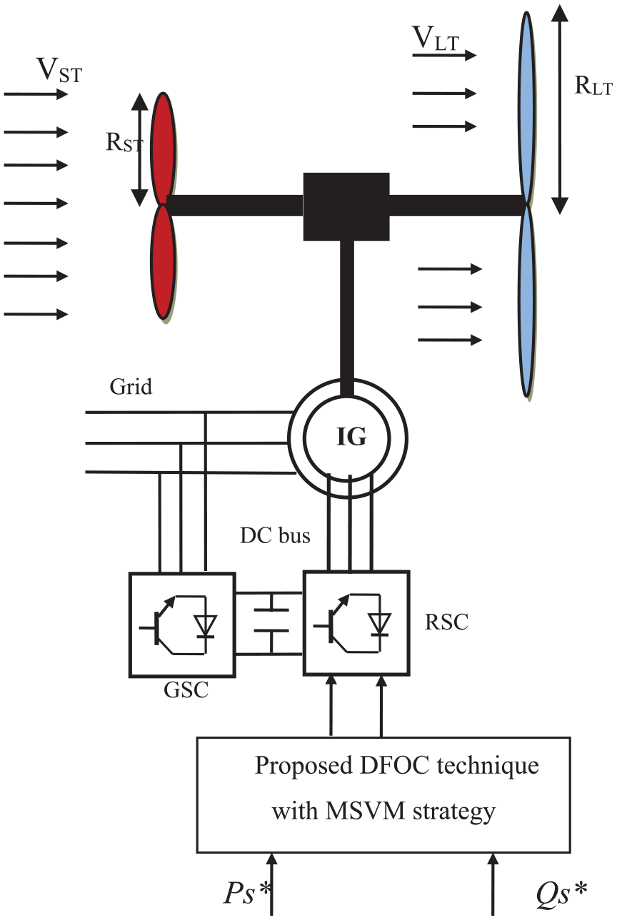
Block diagram of CRWP with an IG controlled by DFOC strategy.
In the same way, the total torque is the sum of the torque of the large turbine and the torque of the small turbine and it is shown in equation (2).

where, T LT and T ST are the torque of the large turbine and the small turbine.
The torque produced by the large and small turbines can be expressed by equations (3) and (4).
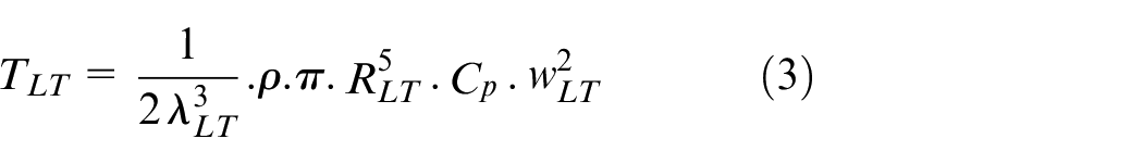
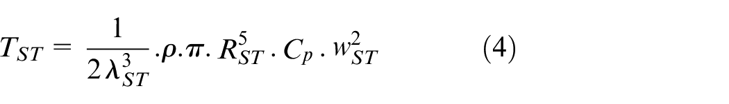
where, ρ is the air density, λLT and λST are the tip speed ration of the large and small turbines, w LT and w ST are the mechanical speed of the large and small turbines, and R LT and R ST are the blade radius of the large and small turbines.
The tip speed ratios of the large and small turbines can be expressed by equations (5) and (6).
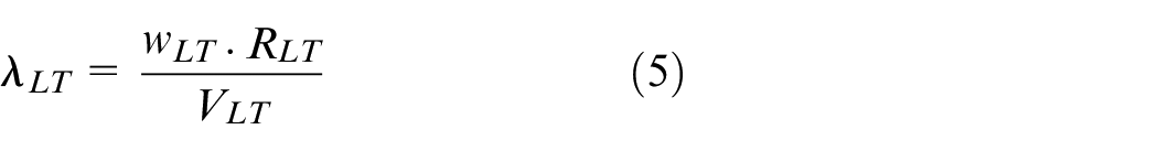
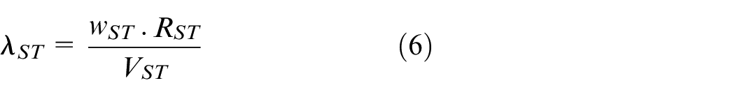
where, V LT is the speed of the unified wind on large turbine and V ST is the WS on small turbine.
The WS at any point between the two turbines can be calculated using equation (7). This equation has been explained in several works. 41
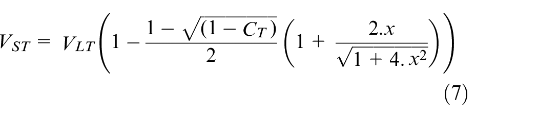
where, x is the distance from the large turbine disk, C T the trust coefficient (C T = 0.9), and V ST is the speed of the disturbed wind between rotors at point x.
The distance between the large and small turbines is 15 m. On the other hand, the Cp is given by (8):
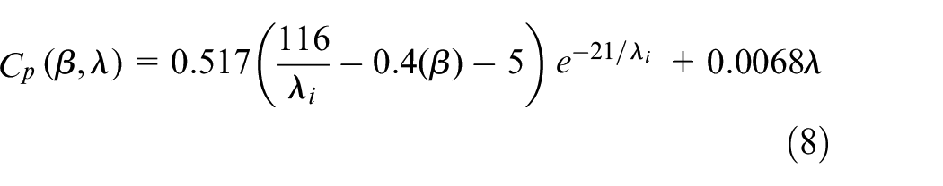
with:
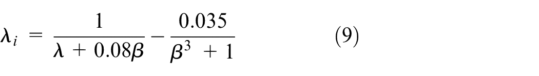
where, β is pitch angle (β = 0 in this research).
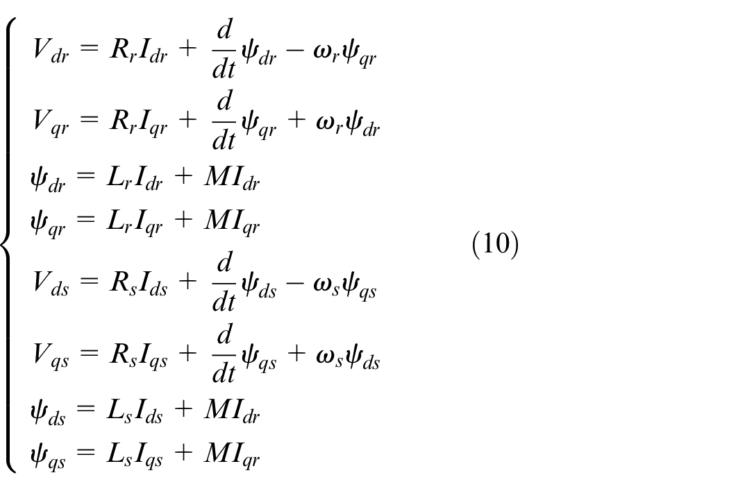
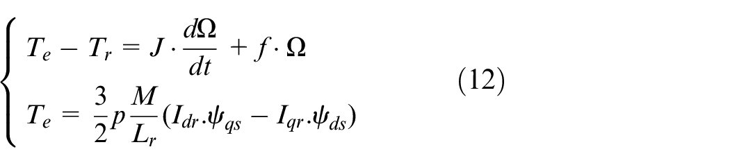
In the field of power system using a variable-speed wind turbines, the IG is among the most suitable generators of all other generators such as a synchronous generator. This is due to the characteristics that make it more convenient. Moreover, this generator is durable, easy to control, needs low maintenance, and is cost-effective. The mathematical form of this generator can be given using the Park transformation. The mathematical form of this generator is detailed in works.42,43 Equations (10) through (12) represent the mathematical form of the generator used in this paper, where equation (10) represents both the voltages and fluxes of the IG. Regarding the mechanical part of the IG, it is represented in equation (12), where this equation gives the relationship between speed and torque. However, torque is calculated using flux and current, where we need to measure current, and flux is calculated using voltage and resistances (stator and rotor resistance).
There are several controllers used to regulate the Ps and Qs of the IG-based wind turbine such as FL, PI controller, SMC technique, NN technique, high-order SMC,…etc. In the next section, a new, more robust nonlinear command is proposed, which relies on the STA technique, NN technique, and SC technique. This new controller is different from the rest of the other controllers and is characterized by simplicity and ease of implementation, and it has been suggested to improve the advantages of the DFOC technique for the IG-CRWP system.
Proposed NSSTC technique
To simplify the idea of the NSSTC technique and ease its use, the mathematical form of the SSTC technique is first given. The NSSTC technique is a modification of the SSTC technique, and to understand the working principle of the NSSTC technique, one must first understand the working principle of the SSTC technique.
Design of SSTC technique
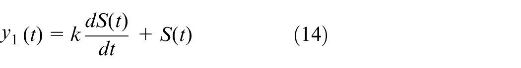
In this section, a novel technique was suggested to ameliorate the characteristics and characteristics of the DFOC technique of the IG-based CRWP system, where the SC technique theory was combined with the STA technique to regulate the Ps and Qs. The designed SSTC controller is more robust than SC technique and STA technique. However, the SSTC controller is simple, so can be used in any control scheme. The idea is to combine two different controllers in principle to obtain a robust strategy as well as minimize the chattering phenomenon. This new nonlinear controller is characterized by ease of implementation and simplicity. In addition to the high durability as a result of using two nonlinear strategies together, outstanding performance is obtained. Also, there are few gains, which makes it easier to adjust and change the dynamic response. The SSTC strategy is not related to the mathematical model of the system, which gives it an additional advantage that makes it give satisfactory results if the machine parameters change. The working principle of this controller can be illustrated by equation (13).

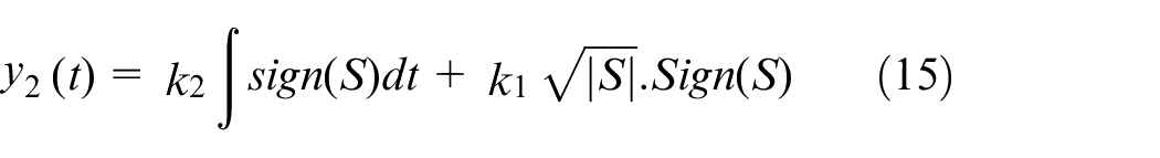
where, y1(t) represents the part of SC technique and y2(t) represents the part of STA technique using the sliding surface S:
Thus, the command input of the SSTC controller is obtained as equation (16).
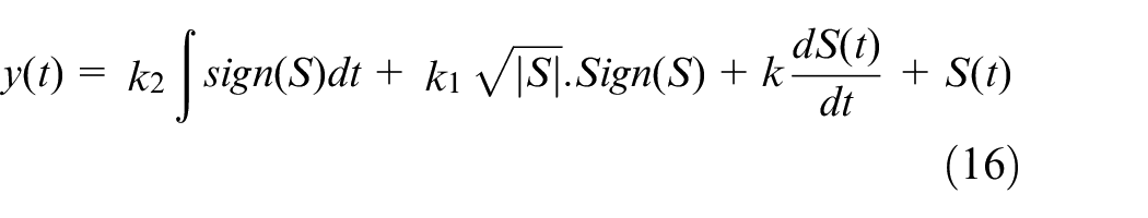
where the parameters K, K1, and K2 are used to tune the proposed SSTC technique to smoothen the controller and minimize the chattering phenomenon and Ps/Qs ripples.
The suggested nonlinear technique is to develop the STA technique by using the SC technique. The SSTC strategy is easy to apply to simple and complex systems, as it is applied directly to the system without resorting to complex calculations. It only requires knowledge of the error or surface. The stability of this controller can be confirmed by using Lyapunov’s theory (LT), as this technique is considered one of the most famous methods used to ensure the stability of controllers. Equation (17) represents the stability condition of the controller, and it can be expressed in LT by equation (18).

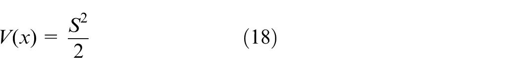
where, V(∞) =∞, V(0) = 0.
To obtain information about the stability of the SSTC technique, the derivation equation (18) is calculated. If
To be stable the condition for slip variable S (x, t) must be met is that the derivative of the function V must be less than 0. The derivative of the function V can be expressed by equation (16).

Among the objectives of the proposed nonlinear controller is to force the state trajectory to operate on the surface S = 0. The surface is selected according to system constraints as it is presented in section 5, where the design process using the intelligent SSTC technique for the DFOC technique will be detailed. To ensure the convergence of the finite time to the surface, the condition must be fulfilled. The derivation of the LT is negative, and this is called the inequality of the gravitational state. Therefore, a stronger case must be respected to ensure that S (x, t) converges toward 0 at a given time. Therefore, a non-linear gravitational state η is used to ensure stability and convergence toward 0. Thus, we can write a stability condition as follows:

where, η is the positive gain.
if
if
For the condition S ≠ 0 the following equation can be written:

Starting from theuij0 previous equations, we can write the following relationship condition:

Therefore, in order for the condition of the equation (23) to be fulfilled, the values of K, K1, and K2 must be positive and not null.

Figure 3 shows a block diagram representation of the SSTC technique used in this work. This technique is a simple scheme and robust compared to SC and STA strategies, which will be used to ameliorate the characteristics of the DFOC technique of the IG-CRWP system with the inverter controlled by the MSVM technique.
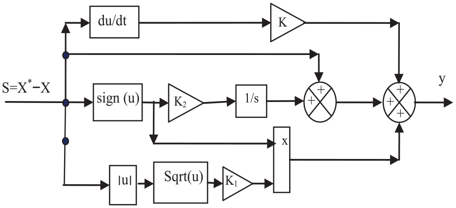
The SSTC technique.
Using a function of the Sign(u) type causes several problems and defects in the SSTC technique, which is undesirable. Among these problems are chatter, high ripples, and low current quality. All of these problems cause undesirable results, as they can reduce the life of the system, increase regular maintenance, increase costs, and give undesirable operation. Therefore, it is necessary to overcome this problem, as neural networks are used as a suitable solution to replace the Sign(u) function. Neural networks were chosen as a suitable solution because of their characteristics, such as accuracy, high robustness, and their lack of relation to the mathematical model of the system.
Design of NSSTC technique
The proposed controller in this section is a neural SSTC technique. This suggested technique is a modification of the traditional SSTC technique, where sign(U) is replaced by NN techniques. Figure 4 represents the architecture of the proposed NSSTC technique. Through this figure, we find that this proposed controller is simple and can be accomplished easily. This designed technique is robust than traditional SSTC technique and PI controller. Also, the use of NN techniques with SSTC technique leads to a more accurate and robust controller.
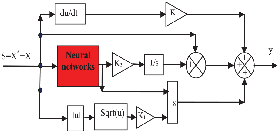
Proposed NSSTC controller.
NN techniques are one of the most popular and widely used techniques of artificial intelligence, especially in the field of control. 44 This technique originale from a machine learning algorithm called Perceptron. In the fifties and sixties of the last century, NN techniques were developed by the scientist Frank Rosenblatt, as they became more effective and can be used in all fields such as medicine, signal processing, and electronics. 45 NN techniques are of several types, the most famous of these types are recurrent NNs (RNNs), convolutional NNs (CNNs), feedforward NNs (FNNs), backpropagation NNs (BPNNs), generative adversarial networks (GANs), Modular NNs (MNNs), Perceptron and Multilayer Perceptron NNs (MPNNs), deep NNs (DNNs), Radial basis function artificial NNs (RBFANNs). 46 But FNN technique is among the most famous of these types and the most widely used, as it is characterized by simplicity, accuracy, and high response speed. Also, this type of network is characterized by the fact that the information takes only one direction, as the information moves from the input nodes to the output nodes through the hidden nodes. Moreover, there are no cycles or loops in the FNN technique, which makes it quicker to respond compared to other types. 47
In FNN technique, one hidden layer or multiple hidden layers can be used. As it is known, the fewer the number of hidden layers, the more the response speed is very large, and the time of information arrival from the entry layer to the exit layer is very small. FNN technique is used to improve the characteristics of the SSTC technique. The advantages of the FNN technique are used to develop the SSTC controller and make it more efficient and robust compared to other types. Moreover, the SSTC controller based on FNN technique is among the new nonlinear commands first suggested in this work to improve the features of the IG-CRWP system.
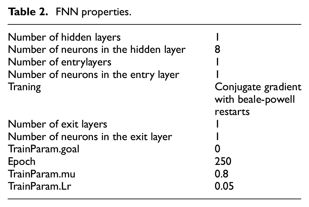
Since the designed NSSTC controller can be used in several fields such as electronics, wind power, and electrical machinery control. This proposed nonlinear controller is used to minimize the Ps/current fluctuations and improve the dynamic response of the IG-based CRWP system. The use of the NSSTC technique improves current quality, reduces periodic maintenance, reduces SSE for both Ps and Qs, and increases durability significantly. For the embodiment of the FNN technique, a Conjugate gradient with beale-powell restarts was used. This training algorithm is simple and can be applied in Matlab software using traincgb. In NSSTC technique, we have one input which is the error (S =X* - X), and one output. Only one hidden layer containing eight neurons was selected. On the other hand, one neuron was selected for each of the entry and exit layers. The characteristics of the FNN technique used to improve the features of the SSTC technique are listed in Table 2. Figure 5(a) shows the FNN training, where are the following values used: TrainParam.show is 50, TrainParam.Lr is 0.05, TrainParam.goal is 0, TrainParam.mu is 0.8, Coeff of acceleration of convergence (mc) is 0.9, and TrainParam.eposh is 250. Also, functions Tensing, Purling, trainlm were used in order to embody this proposed NSSTC technique. Figure 5(b) shows the training plot of the FNN technique. From this figure, the best training performance is 0.0012737 at epoch 53. The Gradient, Mu, and Validation Checks are shown in Figure 5(c) and they represent the properties of the FNN technique. From this figure, the validation checks, Mu, and best Gradient are 0, 0, and 0.29087 at epoch 54, respectively. In addition, the error plot of the FNN technique is shown in Figure 5(d). Through this figure, we find that the targeting field is [−1 1] and the training value is R = 0.99738, and the output is given by (output = 0.99*Target+−0.0017).
FNN properties.
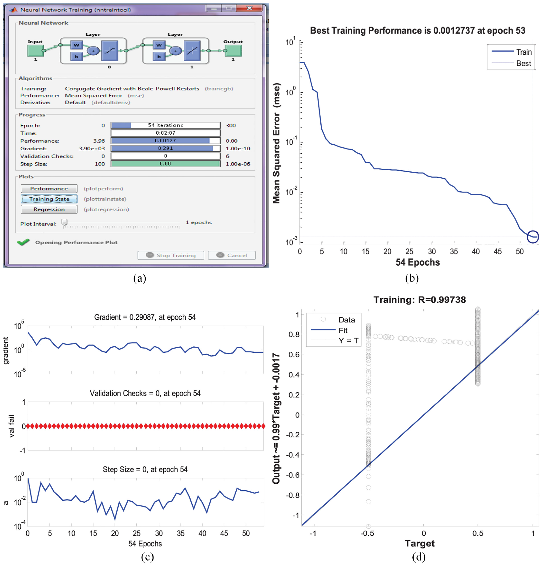
Characteristics of the conjugate gradient with beale-powell restarts: (a) FNN training, (b) training plot, (c) gradient and val fail, and (d) error plot.
The obtained intelligent robust controller is used to improve the performance and effectiveness of the DFOC technique and thus improve the quality of current and energy generated by the IG-based CRWP system. Among the advantages of the suggested intelligent robust technique is that it is algorithmic simple, can be used easily, and response time is very fast and more accurate compared to the classical PI and SSTC controllers.
Figure 6 represents the internal shape of the FNN technique used in this work. This shape was obtained by using a Matlab software. In this form, this FNN technique has one input and one output. Moreover, it is noted that this FNN technique consists of layer 1 and layer 2. In Figure 6, a function of type Tansing is used to perform layer 1. In the case of layer 2, a function of type purelin is used. As is known, in NN techniques there are three layers used, the first layer, which represents the inputs, the middle layer or hidden layer, and the outer layer, which represents the outputs. The middle layer used in this work consists of eight neurons, these neurons were selected according to the response of the FNN technique.
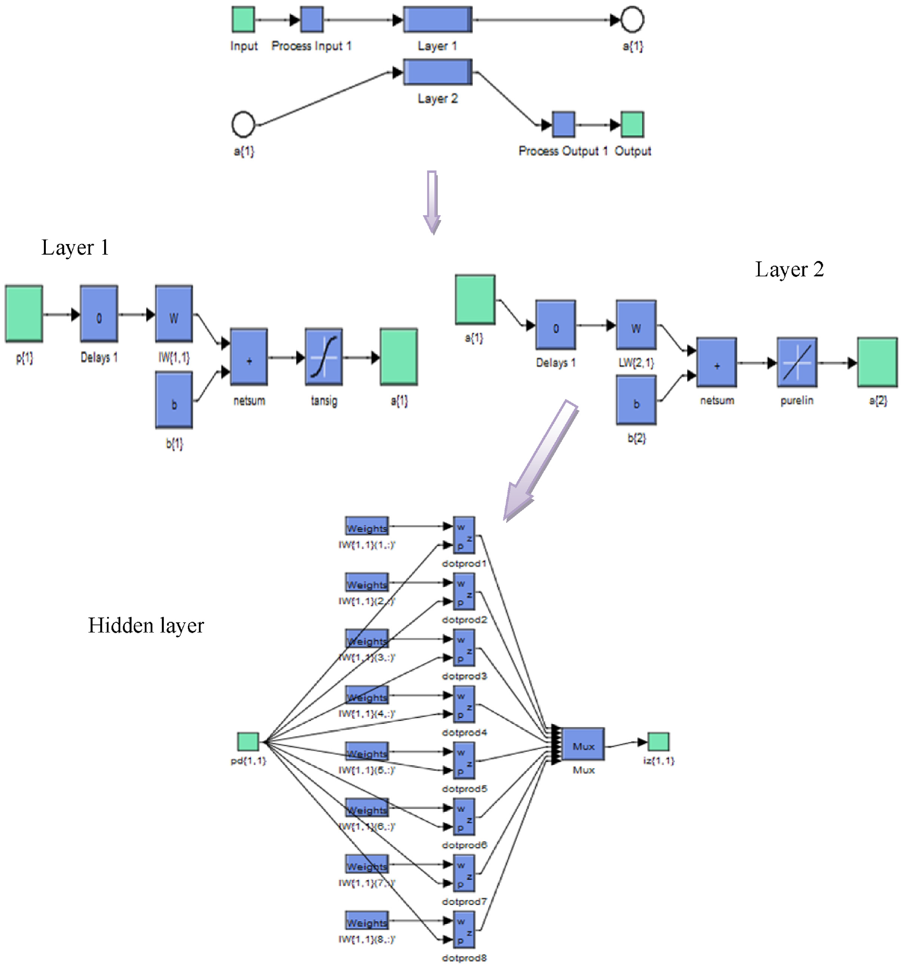
Structure of the NN controller.
Traditional DFOC strategy
The DFOC technique based on the traditional PI controllers (DFOC-PI) is among the simplest commands in the field of electrical machinery control. 48 It can be accomplished easily compared to some controls such as DTC, BC, and DPC technique. 36 This command uses a PI controller instead of using HCs, as used in the DTC as well as in the DPC technique. Among the advantages of this technique is that it is very simple, which leads to a reduction in the financial cost of implementation. 49 This command has been applied to several electric machines such as induction motors and synchronous motors. 50 In addition, this technique is detailed in Amrane et al., 10 Amrane and Chaiba, 12 where equation (24) represents the principle of the DFOC strategy.

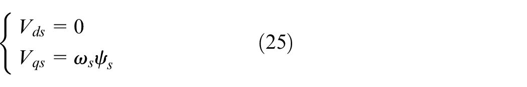
From equation (18), we can write:
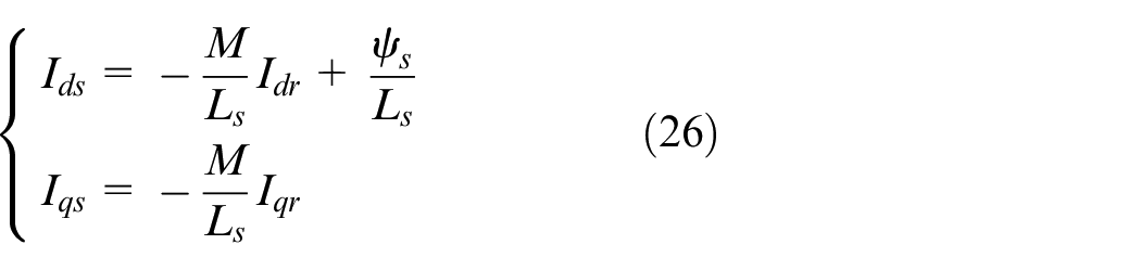
Using equations (24) and (25) in equation (10), the shape of the stator currents becomes:
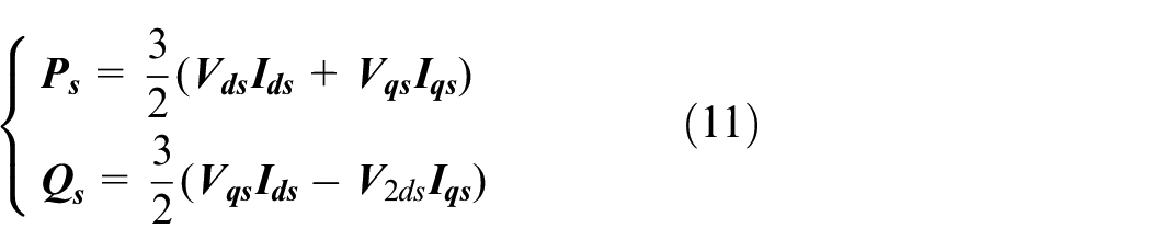
Equation (11) which represents the Ps and Qs becomes as follows:
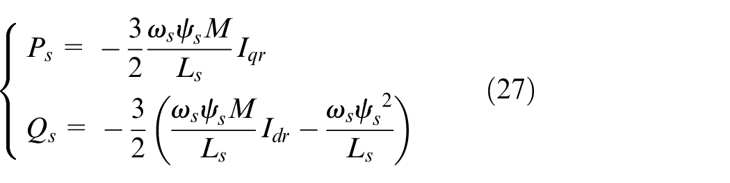
The torque equation is:
The rotor voltage can be written as:

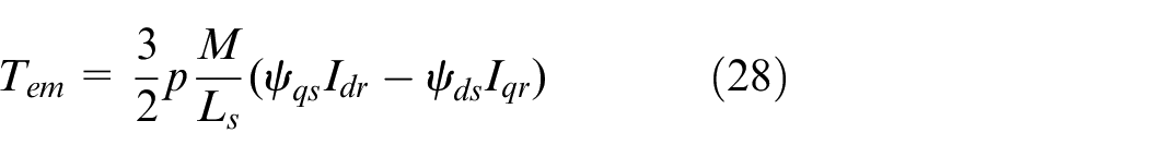
Therefore, the current can be written in terms of voltage as follows:
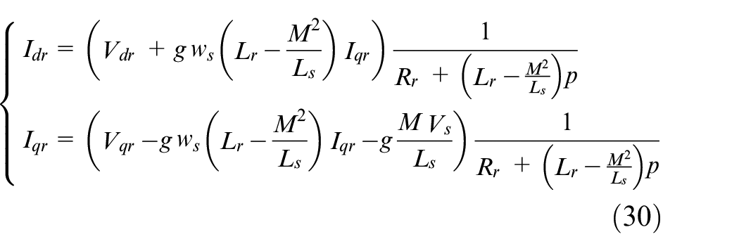
The DFOC strategy is used to command the generator inverter, a park transformation is used to obtain three-phase voltage. In addition, the DFOC strategy is used to obtain reference values for both direct and quadrature rotor voltages (V dr * and V qr *) using a PI controller.
Figure 7 represents the DFOC technique of controlling the IG-based CRWP system using the two PI controllers. In this technique, the reference values of both the quadrature and direct rotor voltage are calculated from the error of the rated power and the reactance. The error in the Ps is the difference between the reference value and the measured value. Moreover, the reference value of the direct rotor voltage is related to the error in Qs.
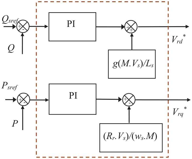
Block diagram of the traditional DFOC technique.
Regarding the reference value of the quadrature rotor voltage, it’s affected by a change in the error value of the Ps.
In this work, a variable WS is used, where the reference value of the Ps (Ps ref ) is calculated using the maximum power point tracking (MPPT) and its value is related to the WS. Also, the reference value of the Qs (Qs ref ) is set at the value 0 VAR. Thus, the behavior of the traditional DFOC technique is studied compared to the proposed DFOC-NSSTC technique in the case of variable WS.
As it is known, the simplicity of the command and the ease of its implementation are among the main advantages of the DFOC strategy. However, there are several drawbacks that limit the effectiveness of this technique, such as large Ps ripples, high THD value, slow dynamic response and so on.
These problems have been overcome in this work using a new nonlinear command based on the SSTC technique. On the other hand, to ameliorate the characteristic of the DFOC technique of the IG-CRWP system using the traditional PWM technique, a proposed NSSTC controller can be used in the place of the traditional PI controller, as well as the use of MSVM strategy in the place of the PWM technique. In this way, more powerful technology and advantages are obtained, which leads to better quality of the electric current. This designed nonlinear DFOC-NSSTC strategy will be explained in next section of this work.
Proposed DFOC strategy
In order to achieve a minimum power ripple, a higher steady-state tracking accuracy and a low THD value of the current and to reduce the design dependence of the controller on the precise IG model, the DFOC strategy based on NSSTC technique is designed in this section. The NSSTC technique is used to regulate the Ps/Qs and reduce the THD value of the current. The proposed DFOC technique based on a NSSTC technique is simple algorithm, robust strategy and easy to implement. It consists in replacing the PI and the PWM of the DFOC technique by imposing the NSSTC controller and MSVM technique. The suggested DFOC-NSSTC technique is shown in Figure 8. The NSSTC controller has the advantage of working without a mathematical model of the system, which makes it simple to design. The application of the NSSTC technique ensures the decoupling between the Ps and Qs control. Moreover, robust control based on the NSSTC technique is characterized by its robustness and easy to implement compared to high-order SMC technique. Consequently, the torque ripple and the THD current will be minimized.
The DFOC-NSSTC technique.
The DFOC technique based on the proposed NSSTC controllers for the IG-based CRWP system is composed of two inputs and two output. The inputs are the Ps error (
The proposed DFOC-NSSTC technique aims to find (calculate) the reference values of both the direct and quadrature rotor voltage (V dr * and V qr *) for controlling the generator inverter, where a park transform is used to get the voltages (Va, Vb and Vc) from the voltages V dr * and V qr *. In addition, the error in the Ps is used to calculate the V qr *, and the Qs error is used to calculate the V dr *.
In the suggested DFOC technique, two NSSTC strategies are applied: an NSSTC strategy for the Ps and another NSSTC strategy for the Qs. The error for Ps/Qs power controllers can be specified as follows:
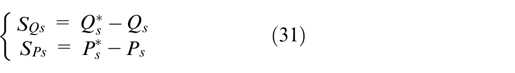
where, S P and S Q are the sliding surfaces of the Ps and Qs.
Starting from equation (31), both V dr * and V qr * can be written as:
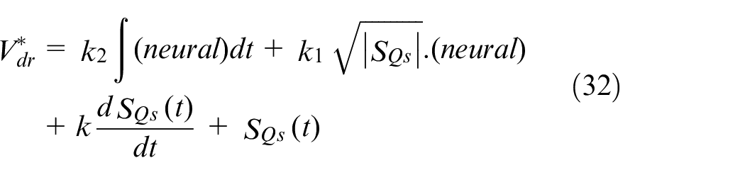
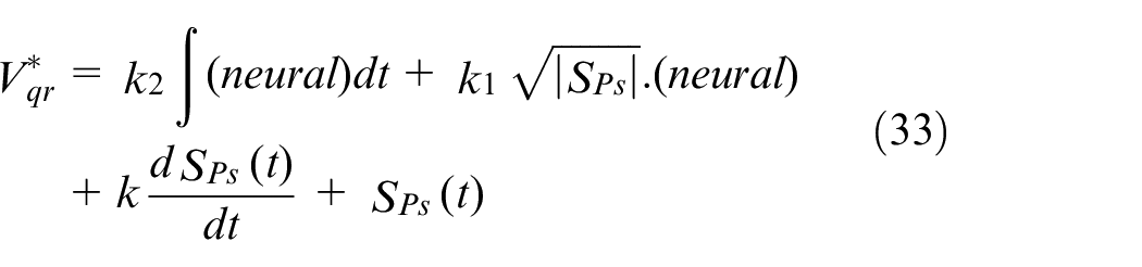
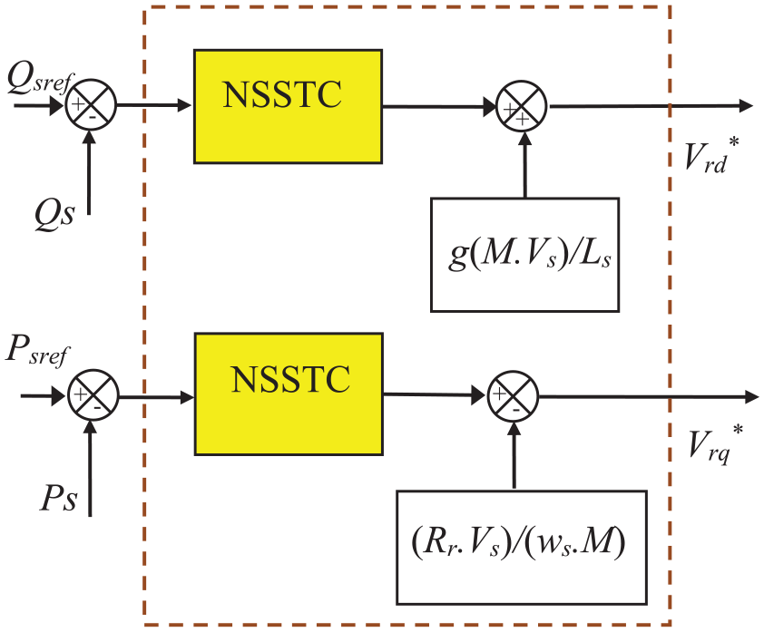
Figure 9 shown the implementation of direct and quadrature rotor voltage references represented by equations (32) and (33), respectively.
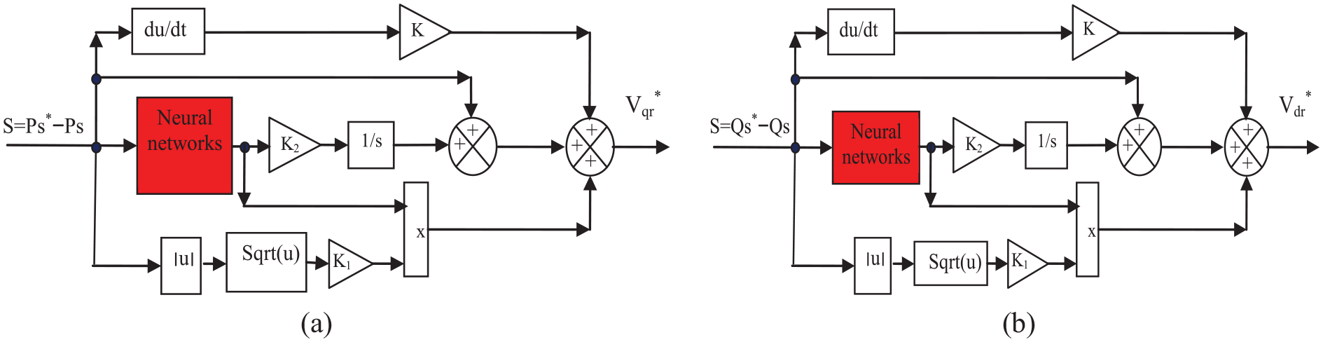
The proposed power controllers: (a) For active power (Ps-NSSTC) and (b) For reactive power (Qs-NSSTC).
Simplicity and ease of implementation are two of the biggest advantages of the proposed Ps and Qs-NSSTC technique to minimize the torque ripples and improve the quality of current. Also, the use of NSSTC technique is not related to the parameters of the studied system, which makes its efficiency higher in case of changing the parameters of the IG-CRWP system.
In the DFOC-NSSTC strategy, a new technique called modified SVM strategy is used to control the IG inverter due to its simplicity and ease of implementation. Moreover, this modulation strategy can be applied to a MLI easily compared to the traditional SVM technique. This modulation is proposed to solve the complexity of the SVM technique. In Boudjema et al., 51 Benbouhenni et al., 52 this method has been experimentally implemented for the control of a classic inverter, where the experimental results showed the characteristics of this technique compared to both the SVM and PWM strategies. The MSVM technique is obtained from the SVM technique based on calculating both the maximum and minimum values of 3-phase voltages. Its advantage is that it is a very simple modulation technique that can be easily implemented in practice, unlike the SVM technique, which is characterized by the complexity of the computational algorithm and is difficult to implement on a MLI. This modulation strategy is explained in Benbouhenni and Bizon, 20 Habib and Bizon, 22 so it will be briefly presented here.
The following table (Table 3) shows a comparative study between the designed nonlinear DFOC-NSSTC strategy with some of the most famous and used control techniques, such as IFOC, DPC, DFOC, DTC, and BC techniques. From Table 6, we note that the designed nonlinear DFOC technique is more robust and performant (in terms of improving the THD value and dynamic response) than the rest of the strategies.
A comparative study between the DFOC-NSSTC with some strategies.

Note: low3(−), acceptable2(+), good4/ high1 (++), excellent5(+++).
Figure 10 represents the MSVM strategy of the two-level inverter. From this figure, we notice that this modulation strategy does not use complex arithmetic like the traditional SVM strategy. Also, this method can be easily implemented on a MLI to obtain lower current ripples and a constant frequency. 20
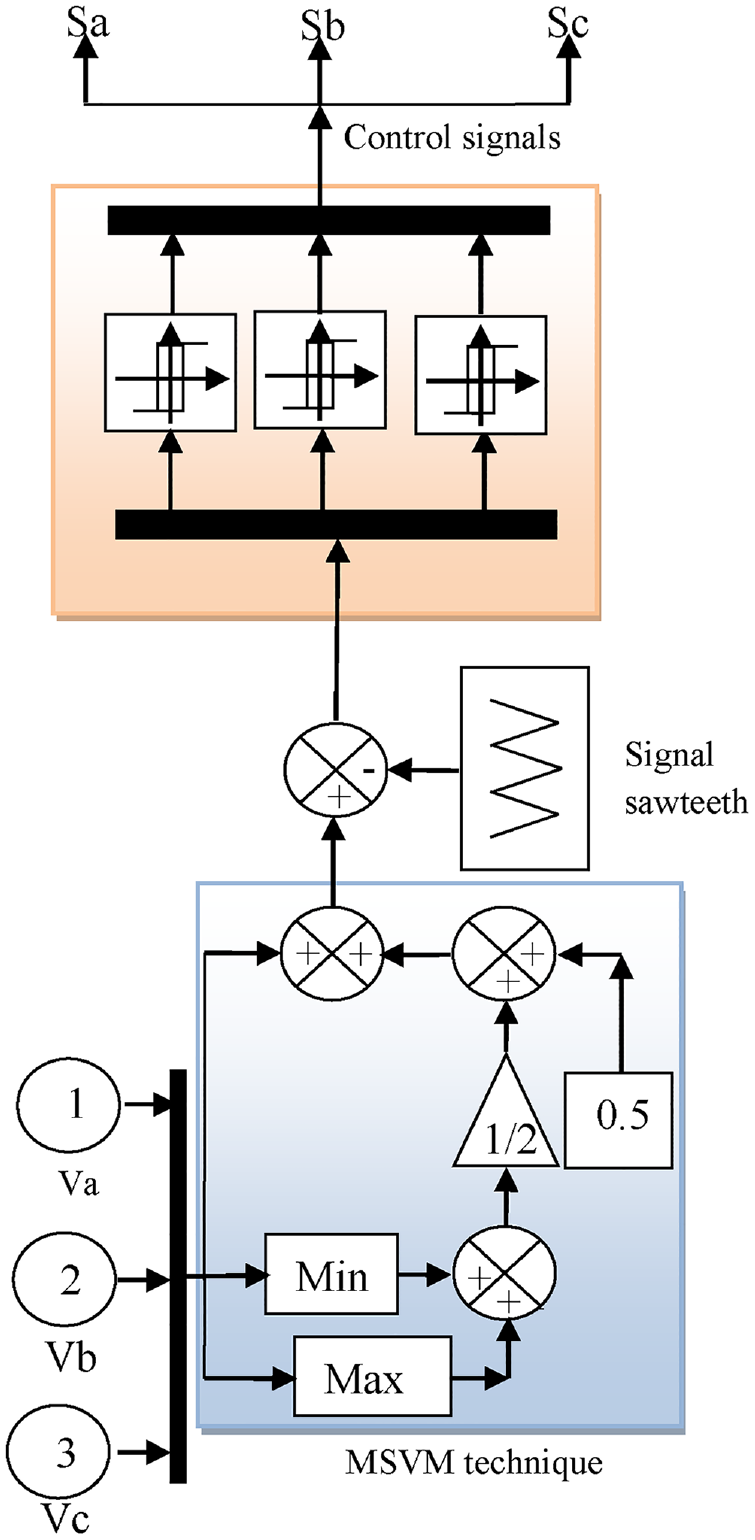
MSVM strategy.
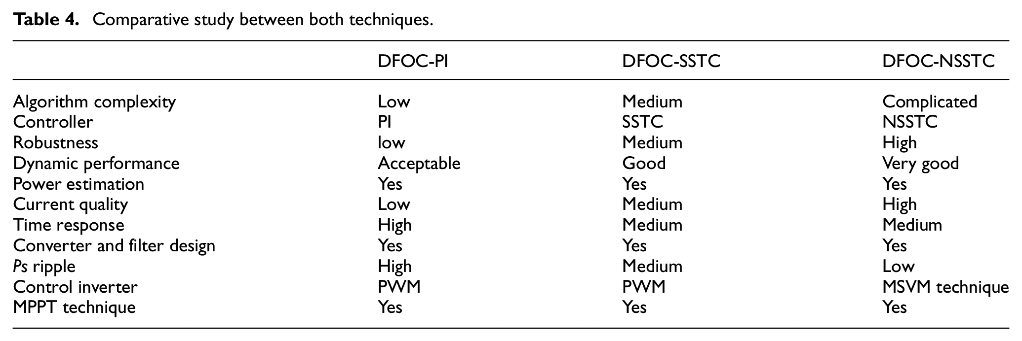
The work aims to verify the behavior of the proposed strategy (DFOC-SSTC) compared with both DFOC-PI and DFOC-SSTC. Therefore, it is necessary to give similarities and differences between these strategies. Table 4 presents a comparative study between the designed and the traditional DFOC techniques based on the data presented above, which will be sustained by the numerical results presented in next section.
Comparative study between both techniques.
Results
The designed DFOC strategy with proposed NSSTC controllers was applied for the IG-CRWP system and implemented using Matlab software. The block diagram of the DFOC-NSSTC technique is given in Appendix. Concerning the parameters of the generator and the variable-speed CRWP system used in this work, they are the same as those used in.20,22 The parameters used in this work are as follows: R s = 0.012 Ω, P sn = 1.5 MW, 380/696 V, L r = 0.0136 H, L m = 0.0135 H, J = 1000 kg/m2, R r = 0.021 Ω, 50 Hz, L s = 0.0137 H, p = 2, and f r = 0.0024 Nm/s.
The values of the tuning parameters K, K1, and K2 are 0.5, 20, and 2.4, respectively. A comparison study between the DFOC-NSSTC with the DFOC-PI and DFOC-SSTC techniques was carried out regarding the THD value of current, WS changing, and robustness to IG parameter variations, Ps/Qs ripples reduction, and trajectory tracking.
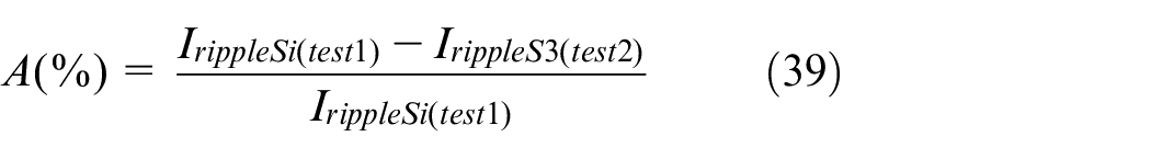
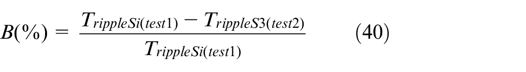
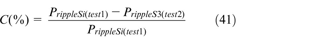
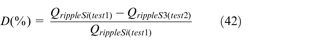
The ripples’ reduction is estimated by the reduction ratio of the THD value (THDR), the current ripple reduction ratio (CRRR), the torque ripple reduction ratio (TRRR), and the active power ripple reduction ratio (PRRR), respectively reactive power (QRRR), given by equations (34)–(38):


where, I rippleSi , T rippleSi , Q rippleSi , and P rippleSi represent the ripples’ value for the current, torque, Qs and Ps of the DFOC-PI technique (S1) and DFOC-SSTC (S2), and I rippleS3 , T rippleS3 , Q rippleS3 , and P rippleS3 represents the ripples’ value for the same variables of the suggested strategy, the DFOC-NSSTC technique (S3).
The reduction ratios will be estimated without (first test) and with changes (second test) in the parameters of the IG to evaluate the robustness of the DFOC-NSSTC, DFOC-SSTC and DFOC-PI strategies.
First test
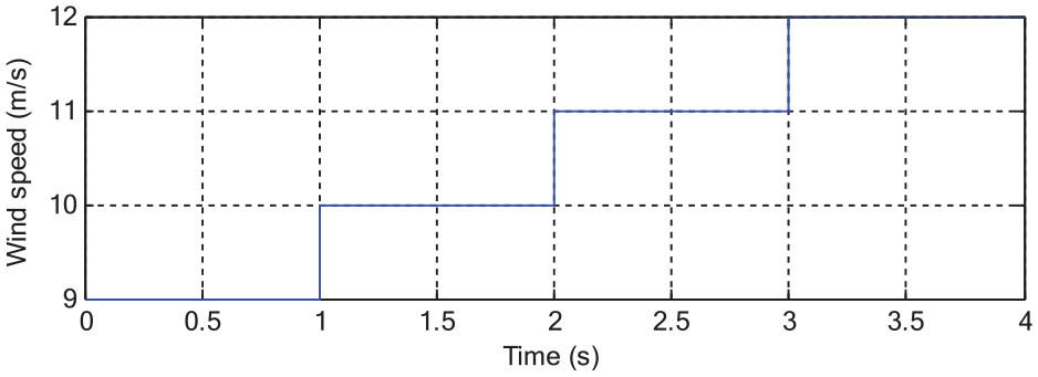
In this test, the variable wind speed represented in Figure 11 is used to study the characteristics of the strategies.
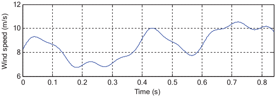
Wind speed profile.
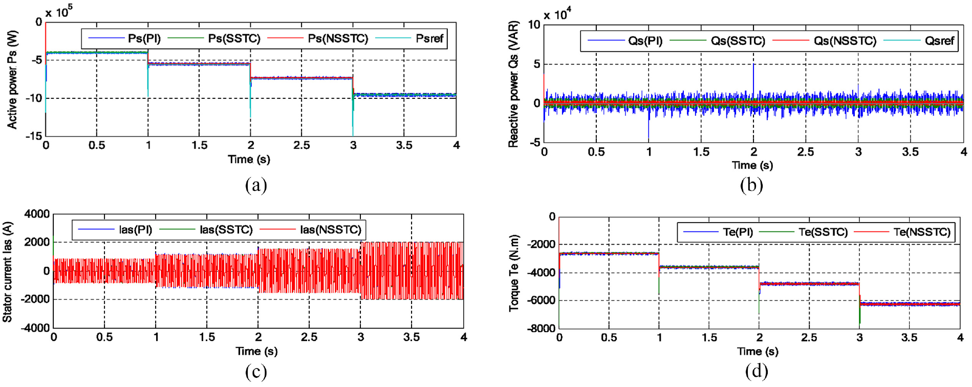
The results obtained from the simulation are shown in Figure 12 and Table 5 for the three DFOC techniques. The current of the three proposed DFOC techniques takes the form of Ps and is related to the WS (see Figure 12(c)). It is noted that the value of the current increases with increasing wind speed and decreases with decreasingwind speed. The measured Ps and Qs of each of the three DFOC strategies follow very well the references values (see Figure 12(a) and (b)). For the three DFOC strategies, the Ps and Qs perfectly track their references values (e.g. see the zoom of the Ps represented in Figure 13(a)). Reactive power is not affected by changes in wind speed, as it remains constant throughout the simulation period. But the NSSTC technique introduces better characteristics in terms of settling time, rise time, overshoot damping and SSE compared to the PI and SSTC controllers, as it will be shown in next figures. Figure 12(d) represents the torque for the three DFOC techniques related to the value of the Ps reference. The torque changes according to the change in active power and wind speed, as the greater the value of the wind speed, the greater the value of the torque.
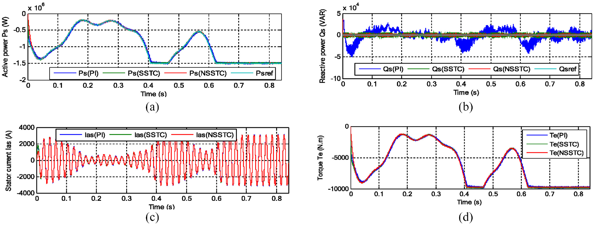
Results of the first test: (a) Ps, (b) Qs, (c) Ias, and (d) Te.
Comparative results obtained in Test 1 for the analyzed strategies.
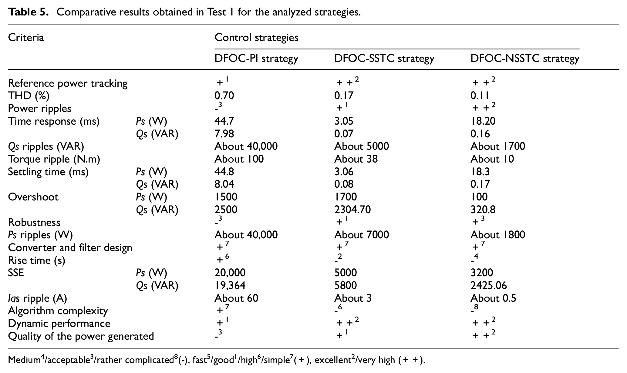
Medium4/acceptable3/rather complicated8(−), fast5/good1/high6/simple7(+), excellent2/very high (++).
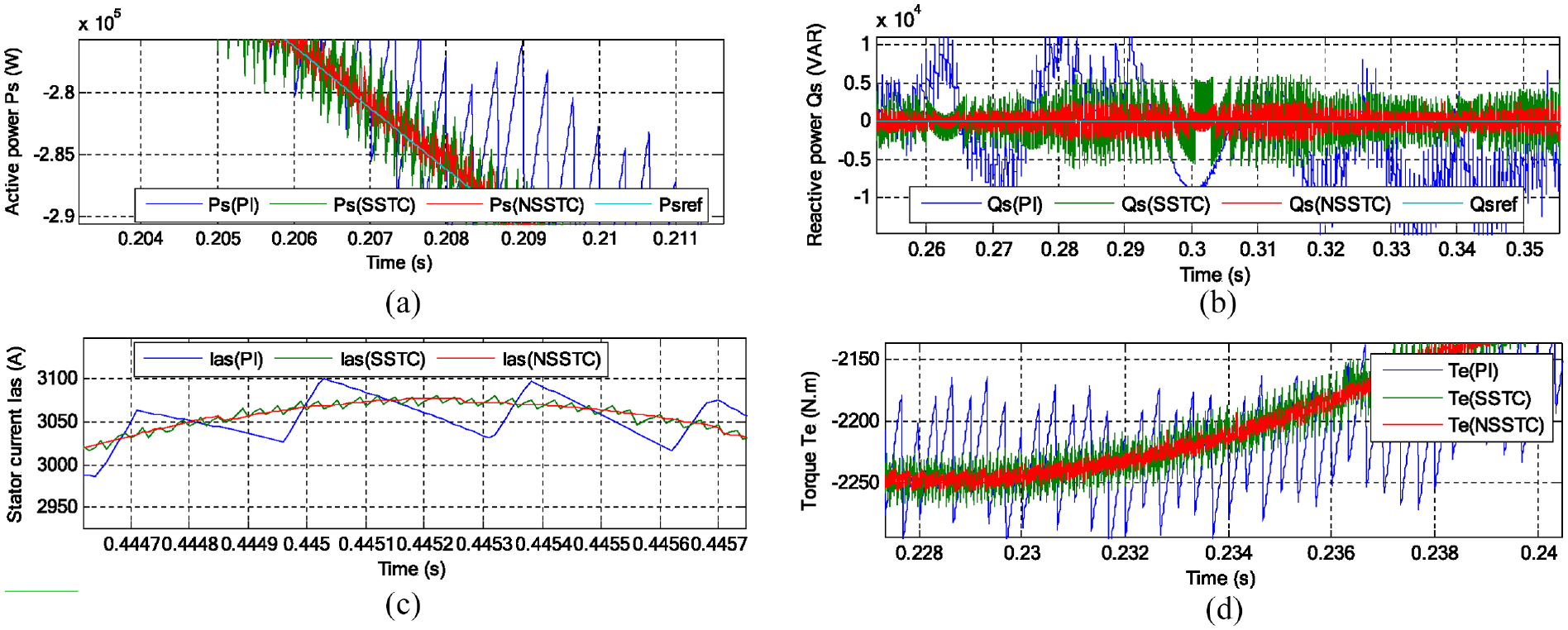
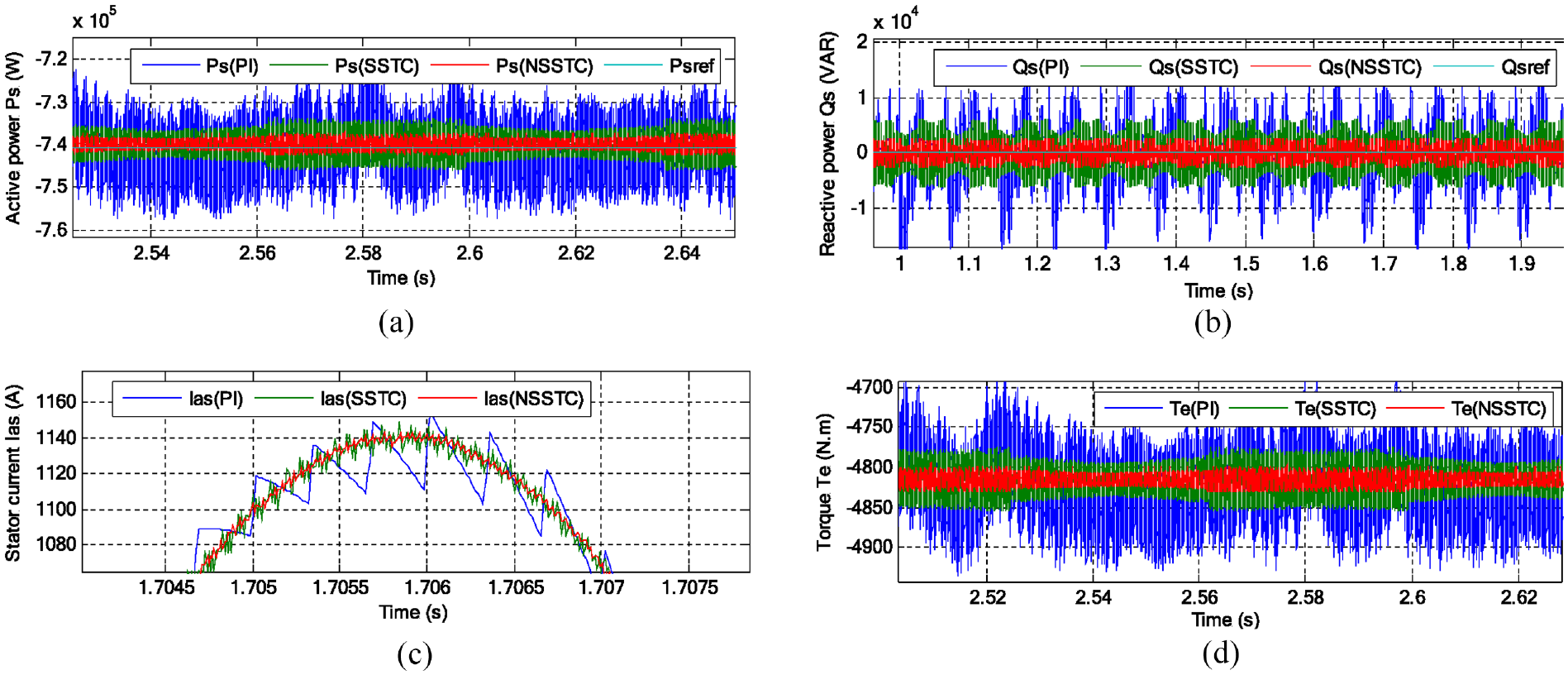
Zoom in the results of the first test: (a) Ps, (b) Qs, (c) Ias, and (d) Te.
The zoom in the current, torque, Ps and Qs are shown in Figure 13(a) to (d), respectively. It can be seen that the designed intelligent nonlinear DFOC techniquewith MSVM technique minimizes the ripples in current, torque, Ps and Qs compared to the DFOC with PI controller and DFOC technique with SSTC controllers. The reduction rate is estimated for the ripples in current, torque, Qs, and Psat 99.17% (CRRRS1S3), 93% (TRRRS1S3), 91.50% (QRRRS1S3), and 95.5% (PRRRS1S3), respectively, compared to the traditional direct FOC-PI using (34)–(38). And at 83.33% (CRRRS2S3), 53.33% (TRRRS2S3), 66% (QRRRS2S3), and 74.29% (PRRRS2S3), respectively, compared to the traditional DFOC-SSTC technique. To further compare the characteristics of these three strategies, the currents harmonic spectra are compared.
Figure 14(a) to (c) show the THD value of the current of the IG-CRWP system for three proposed DFOC techniques. It can be clearly observed through these figures that the THD value is minimized for the designed intelligent nonlinear DFOC-NSSTC strategy (0.11%) when compared to the DFOC-PI strategy (0.70%) and DFOC-SSTC strategy (0.17%). The THD reduction can be estimated at 84.29% (THDRS1S3) compared to the DFOC-PI strategy, and at 35.29% (THDRS2S3) compared to the DFOC-SSTC using equation (31). Based on the results above, it can be said that the DFOC-NSSTC technique with the MSVM strategy has proven its efficiency in minimizing chattering phenomena and power ripples. Also, improve the quality of current compared to the traditional DFOC technique and DFOC-SSTC technique. On the other hand, it is noted from Figure 14 that the traditional strategy represented by DFOC-PI gave a large amplitude of the fundamental signal (50 Hz) of current compared to the amplitude of both the strategies DFOC-SSTC and DFOC-NSSTC, where the amplitude value was 3079 A for the DFOC-PI strategy and the value was 3075 A for both DFOC-SSTC and DFOC-NSSTC strategies. The same amplitude of the fundamental (50 Hz) current signal for DFOC-SSTC and DFOC-NSSTC strategies can be attributed to the NSSTC gain values and the choice of the number of neurons used in the inner layer.
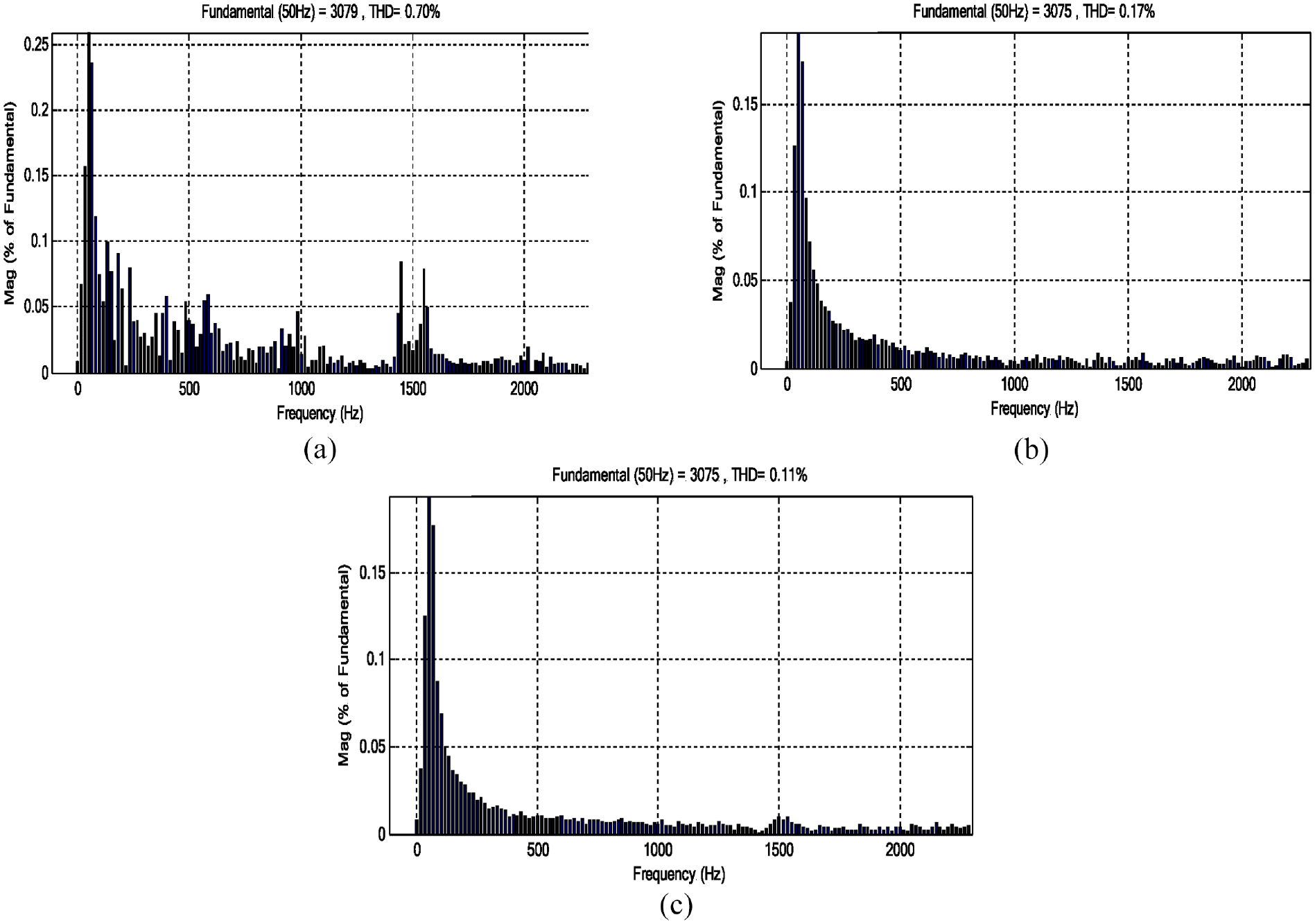
THD of current: (a) DFOC-PI, (b) DFOC-SSTC, and (c) DFOC-NSSTC.
The obtained numerical results in the first test have been summarized in Table 5. Also, Table 5 is a comparative study between the designed DFOC technique and the DFOC technique in all respects. Through this table, it can be said that the proposed DFOC technique has given very satisfactory results in terms of reducing Ps and Qs ripples. Also, the designed DFOC-NSSTC technique improved the dynamic response compared to the DFOC-PI technique. However, the designed DFOC-NSSTC technique provided better results in terms of current, torque, Ps and Qs ripples, and Ps/Qs tracking, resulting a high quality of the produced energy. Also, it is clear that the DFOC-NSSTC technique is robust and performant (see the rise time, SSE, settling time, dynamic response, overshoot, etc.) than the DFOC-PI and DFOC-SSTC techniques. For example, the Ps ripple reduction ratio is about 95.5% and 74.28% compared to DFOC-PI and DFOC-SSTC strategies, respectively. For Qs ripple minimization ratio is about 95.75% and 66% compared to DFOC-PI and DFOC-SSTC techniques, respectively.
Second test
To test the robustness of the DFOC-NSSTC technique, the parameters of the IG are changed as follow: the values of the stator and rotor resistances will be multiplied by 2 and the values of stator and rotor inductances will be divided by 2. The changes that occur at the level of torque, current, Ps and Qs, as well as the value of THD are noted. The same wind speed used in the first test is used. The goal of this test is to find out the most robust strategy capable of overcoming the problem of changing machine parameters.
The obtained results are shown in Figures 15 to 17 and Table 6. From a preliminary observation, we find that the torque, current, active and reactive powers were all affected by the change of the aforementioned parameters (see Figures 15 and 17). But it is worth mentioning that the DFOC-NSSTC strategy with MSVM technique was less affected compared to the DFOC-PI and DFOC-SSTC strategies (see Figures 16 and 17). Also, the decoupling between the Ps and Qs is not ensured in this case, whereas the DFOC-NSSTC strategy with MSVM technique is robust against parameter variations and the decoupling is perfectly ensured (see Figure 15(a) and (b)).
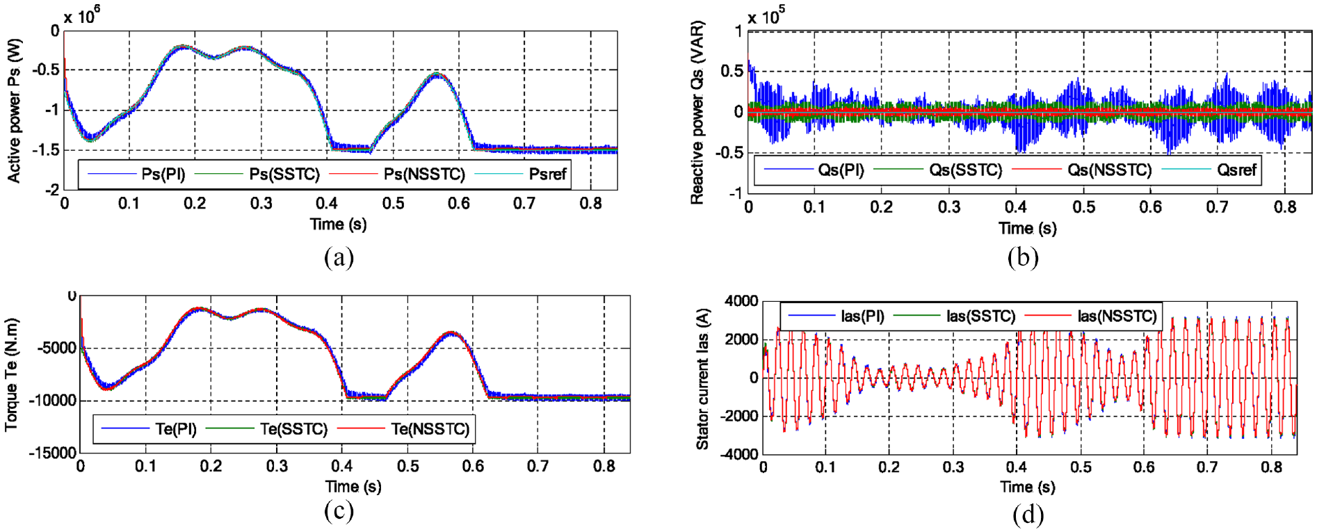
Results in the second test: (a) Ps, (b) Qs, (c) Ias, and (d) Te.
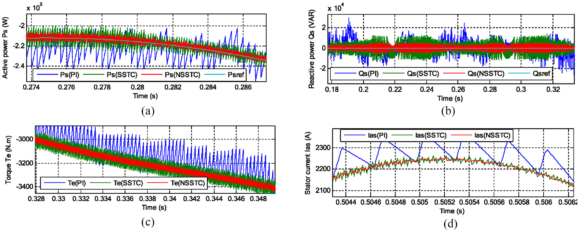
Zoom in the results of the second test: (a) Ps, (b) Qs, (c) Ias, and (d) Te.
THD of current: (a) DFOC-PI, (b) DFOC-SSTC, and (c) DFOC-NSSTC.
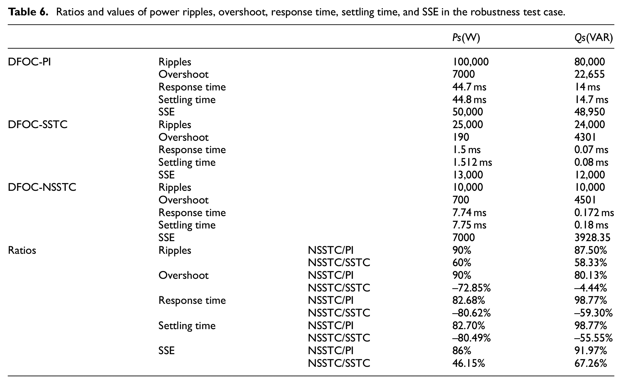
Ratios and values of power ripples, overshoot, response time, settling time, and SSE in the robustness test case.
As in the first test, the measured Qs and Ps follow the references well. In addition, the proposed intelligent nonlinear DFOC-NSSTC strategy with the MSVM technique has a better characteristics in terms of response time, overshot and ripples (see Table 6). Despite the change in the machine parameters, the torque and current continue to change according to the change in wind speed for the three controls (see Figure 15(c) and (d)), with the presence of ripples, as these ripples are larger in the case of the DFOC-PI strategy compared to the other strategies (see Figure 16(c) and (d)).
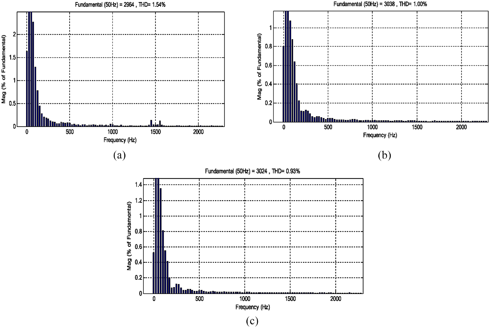
Also, the DFOC-NSSTC technique gave a value of THD that is much lower than the DFOC-PI technique and DFOC-SSTC strategy, and this is illustrated by Figure 17(a) to (c). As is known, the value of THD varies with the number of cycles. The value of THD for DFOC-NSSTC technique with MSVM technique is 0.93% and the value of THD for the DFOC-PI is 1.54% and for DFOC-SSTC strategy is 1%. So, the THD reduction can be estimated at 39.61% and 7% compared to the DFOC-PI and DFOC-SSTC strategies, respectively.
Thus, it can be concluded that the DFOC-NSSTC technique is more performant than the traditional DFOC-PI and DFOC-SSTC strategies. From Figure 17, it is noted that the DFOC-NSSTC strategy provided an amplitude of the fundamental (50 Hz) of current signal that was larger than the amplitude provided by the DFOC-PI strategy and less than the amplitude provided by the DFOC-SSTC strategy. So the amplitude was 2964 A, 3038 A, and 3024 A for DFOC-PI, DFOC-SSTC, and DFOC-NSSTC, respectively.
Table 6 represents the numerical values obtained from the second test of the controls proposed in this work, where the numerical values are extracted for each of the ripples, response time, SSE, overshoot, and settling time of Ps and Qs. For example, the Ps SSE reduction ratio is about 86% and 46.15% compared to DFOC-PI and DFOC-SSTC strategies, respectively. For the Qs SSE minimization ratio is about 91.97% and 67.26% compared to DFOC-PI and DFOC-SSTC techniques, respectively.
The results mentioned in this table clearly show that the DFOC-NSSTC technique is less affected compared to classical DFOC and DFOC-SSTC strategies.
From this table, it is noted that the proposed strategy (DFOC-NSSTC) provided unsatisfactory results in terms of overshoot, response time, and settling time of Ps and Qs compared to the DFOC-SSTC technique. These unsatisfactory results of the proposed strategy can be attributed to the choice of NN parameters (in the number of neurons in the inner layer), as there is no mathematical relationship that determines how to use this strategy. But these drawbacks can be overcome by using other strategies, for example using genetic algorithms to determine the NSSTC controller gain values.
The proposed NSSTC technique is applied to improve the dynamic response, overshoot, SSE, ripples, and THD value of the IG-CRWP system, being one of the best control techniques among the currently existing methods.
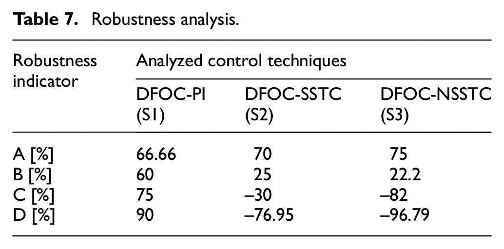
Through the first and second tests, we find that the effect ratio was greater in the traditional DFOC technique compared to the DFOC-NSSTC technique. The robustness indicators are defined and computed in Table 7 to estimate the robustness of strategies analyzed in this paper.
with:
Robustness analysis.
Third test
This test is different from the rest of the tests, as a different wind speed than Figure 11 is used in order to study the characteristics of the control strategies used in this paper. The wind speed used in this test is represented in Figure 18. The graphical results of this test are represented in Figures 19 to 21 and the numerical results are listed in Table 9. From Figure 19 it is noted that the Ps, current, and torque follow the shape of the wind speed change. Well, as the values of these quantities increase as the wind speed increases and decrease as the wind speed decreases with the presence of ripples. The latter is greater in the case of using the traditional strategy compared to other controls, as shown in Figure 20. The Qs is not affected by the change in wind speed and remains close to the reference value (equal to 0) throughout the simulation period (see Figure 19(b)), with the presence of large undulations in the case of using the traditional strategy compared to both DFOC-SSTC and DFOC-NSSTC (see Figure 20(b)).
Wind speed profile.
Results of the third test: (a) Ps, (b) Qs, (c) Ias, and (d) Te.
Zoom in the results of the third test: (a) Ps, (b) Qs, (c) Ias, and (d) Te.
THD of current: (a) DFOC-PI, (b) DFOC-SSTC, and (c) DFOC-NSSTC.
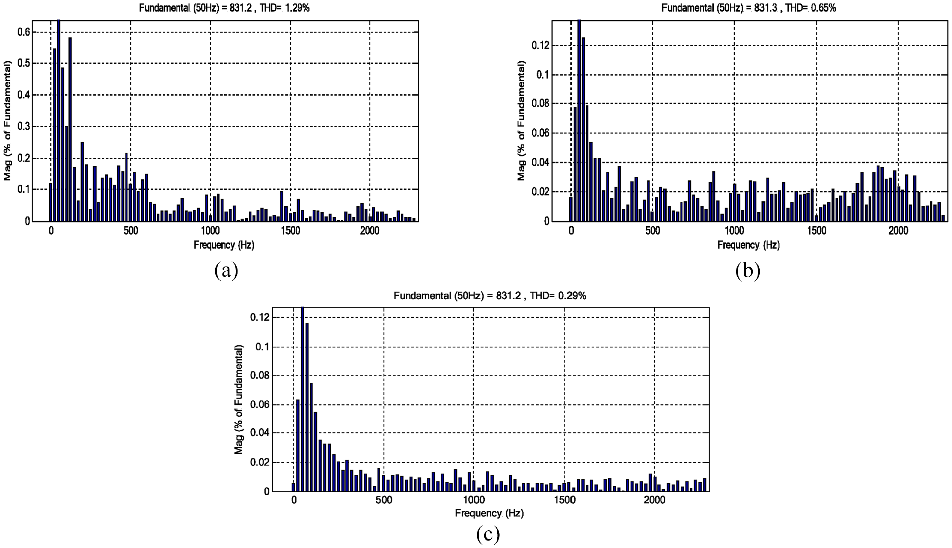
The value of THD of current for the three controls is shown in Figure 21. This figure gives a clear picture of the superiority of the DFOC-NSSTC strategy over other strategies in terms of reducing the value of THD of current. The latter were 1.29%, 0.65%, and 0.29% for DFOC-PI, DFOC-SSTC, and DFOC-NSSTC, respectively. So the reduction rates were 77.51% and 55.38% compared to the DFOC-PI and DFOC-SSTC, respectively. On the other hand, the three strategies used in this work provided very close values for the amplitude of the fundamental signal (50 Hz) of current. Therefore, the amplitude values were 831.2 A, 831.3 A, and 831.2 A for DFOC-PI, DFOC-SSTC, and DFOC-NSSTC, respectively.
The numerical results of this test are represented in Table 8, where the values and reduction percentages are given for ripples, response time, overshoot, settling time, and SSE of Ps and Qs. This table gives a clear picture of the superiority of the DFOC-NSSTC strategy over the DFOC-PI strategy in terms of ripples, response time, overshoot, settling time, SSE of Ps and Qs, and this appears through the high minimization ratios. For example, the Psripples, response time, overshoot, settling time, SSE minimization ratio is about 88%, 82.66%, 77.27%, 71.31%, and 81.72%, respectively compared to DFOC-PI. For the Qs ripples, response time, overshoot, settling time, SSE minimization ratio is about 94.72%, 96.52%, 98.69%, 98.91%, and 84.17%, respectively compared to DFOC-PI.
Ratios and values of response time, power ripples, settling time, overshoot, and SSE in the third test case.
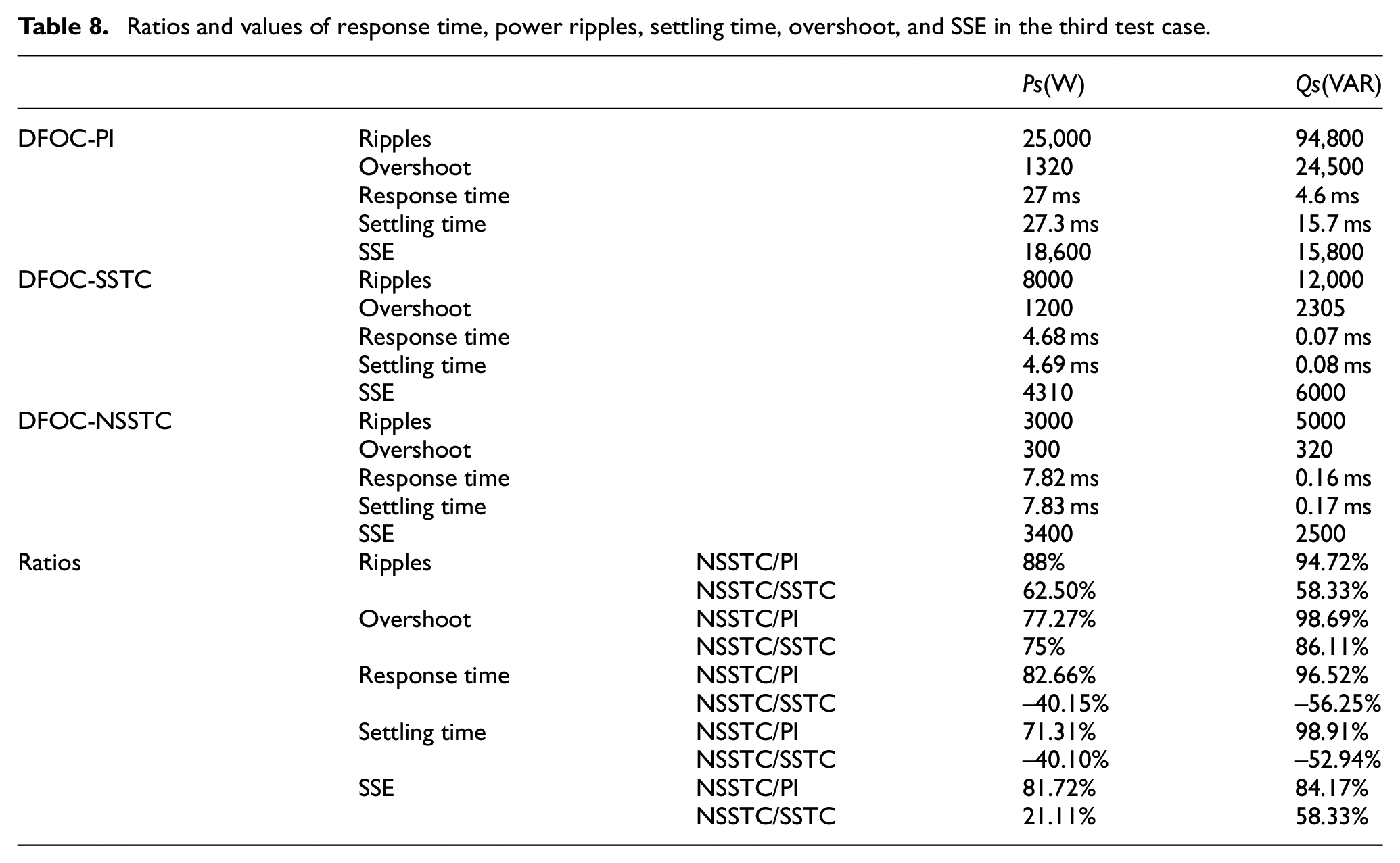
On the other hand, the DFOC-NSSTC strategy reduces the values of both ripples, SSE, and power overshoots by satisfactory percentages compared to the DFOC-SSTC strategy. This ratio was 62.50%, 21.11%, and 75% for ripple, SSE, and overshoot of Ps, respectively. As for the Qs, the percentages were 58.33%, 85.33%, and 86.11% for ripples, SSE, and overshoot, respectively. The proposed strategy has drawbacks in everything related to response time and settling time of Ps and Qs, as it provided unsatisfactory results for these ratios compared to the DFOC-SSTC strategy (see Table 8), which is undesirable.
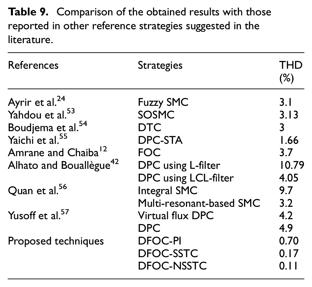
A comparative study between the DFOC-NSSTC technique in this work with some published works in terms of the value of THD is shown in Table 9. Through this table, we notice that this command gave a very good value for THD of current compared to the rest of the other strategies. On the other hand, a comparison is made between the proposed control and some existing strategies in terms of the percentage of reducing the ripples of both Ps and Qs. This comparison is listed in Table 10, where it is noted that the proposed strategy provided high percentages of reducing the ripples of Qs and Ps compared to several strategies such as FOC and DTC, which is a good thing that shows the effectiveness of the proposed strategy in overcoming the problem of energy ripples.
Comparison of the obtained results with those reported in other reference strategies suggested in the literature.
Comparison in terms of power ripples minimization rates.
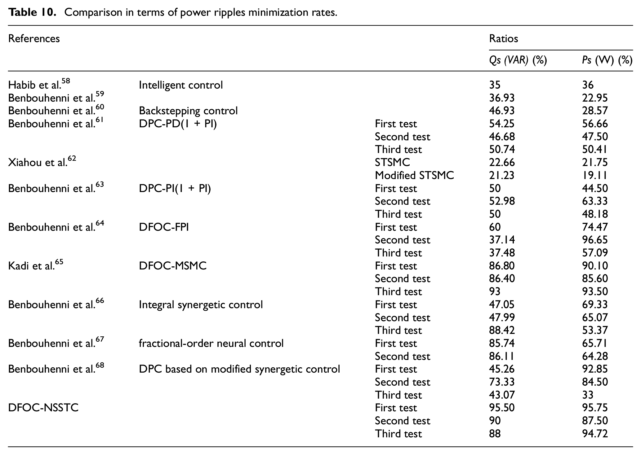
It can be concluded from Tables 9 and 10 that the DFOC-NSSTC technique can be used to ameliorate the quality of the current and the energy produced by the power systems.
Another comparison with existing scientific work has been completed in Tables 11 to 13, where the comparison was made in terms of the percentage reduction in response time, SSE, and overshoot of Ps and Qs. These tables confirm the results of this work and the comparisons made in Tables 9 and 10, where the proposed strategy (DFOC-NSSTC) outperforms several works in terms of reducing response time, SSE, and overshoot of Ps and Qs. The proposed strategy provided high percentages, which indicates that it has efficiency and distinguished performance compared to several existing strategies, making it one of the most prominent solutions that can be relied upon in the field of control in the future.
Comparison in terms of SSE for Ps and Qs.
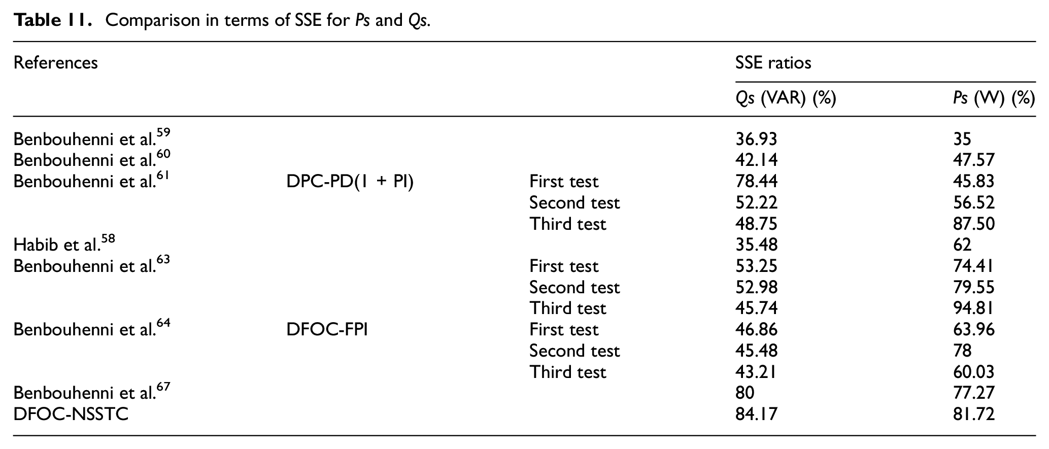
Comparison in terms of overshoot for Ps and Qs.
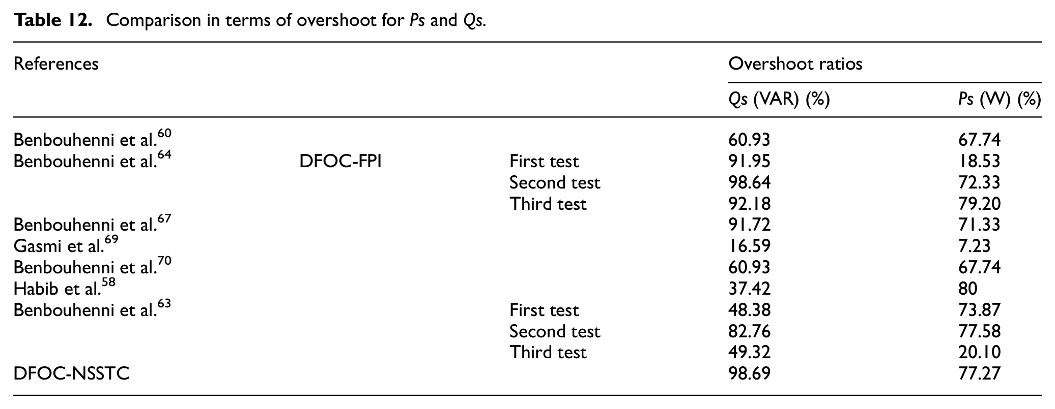
Comparison in terms of response time for Ps and Qs.
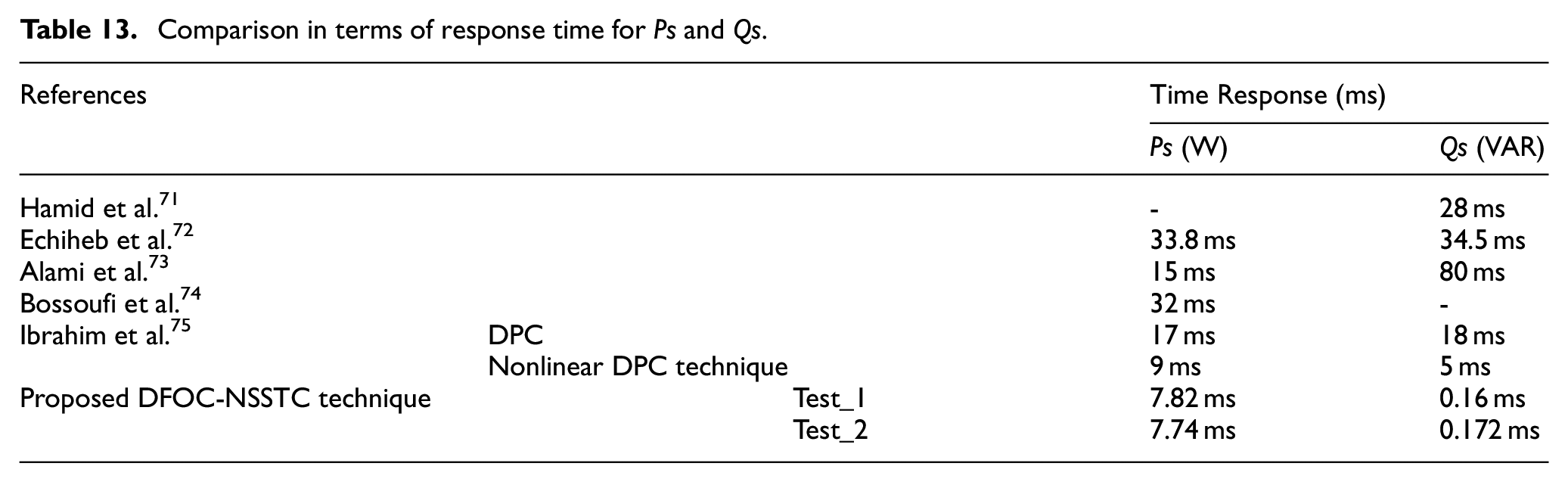
Conclusion
In this paper, a robust and simple nonlinear regulator was proposed to command and regulate the reactive/active power of the IG-based CRWP system. The generator is controlled using the DFOC-NSSTC technique. The proposed nonlinear NSSTC controller is a robust nonlinear controller that minimizes the ripples of the active power, flux, rotor/stator current, torque and reactive power compared to PI and SSTC controllers. The numerical simulation shows that the DFOC-NSSTC technique is robust and performant than DFOC-PI and DFOC-SSTC strategies (see Table 5) and other control techniques (see Tables 9–13)
The simulation results demonstrated the characteristics of the DFOC-NSSTC strategy with MSVM strategy in improving the efficiency and characteristics of the IG-CRWP system compared to the DFOC-PI and DFOC-SSTC strategies. The reduction ratios for active power, torque, current, reactive power, and THD value of current are 95.5%, 93%, 99.17%, 91.5%, and 84.29%, respectively, compared to the DFOC-PI technique. Also, the minimization ratios for reactive power, torque, current, active power, and THD value of current are 66%, 53.33%, 83.33%, 74.29%, and 35.29%, respectively, compared to DFOC-SSTC technique. Through these ratios, we find that the DFOC-NSSTC technique based on MSVM technique is more effective in improving the characteristic of the variable-speed IG-CRWP system. Also, the DFOC-NSSTC technique is more robust than the DFOC and DFOC-SSTC strategies.
So, in summary, the main findings of this research are the following:
A new DFOC technique based on the NSSTC algorithm and MSVM strategy was presented and confirmed with numerical simulation.
The designed DFOC-NSSTC technique reduces the ripples of torque, reactive/active power, and current.
The designed DFOC-NSSTC technique minimizes the THD ratios of current compared with others reference commands suggested in the literature.
In a future paper, to improve the wind power quality produced by IG-based variable-speed CRWP system, an robust control such as fractional-order synergetic command theory will be integrated. The performance obtained and the complexity of the control, will be evaluated compared to the traditional strategies proposed in the literature and the strategy proposed in this paper.
Footnotes
Appendix
Author contributions
Conceptualization, H.B.; methodology, H.B.; software, H.B.; validation, H.B., N.B. and D.Z.; investigation, H.B., L.I. resources, H.B., N.B. and A.M.; data curation, H.B., N.B. and I.C.; writing – original draft preparation, H.B. ; supervision, N.B., L.I., I.C.; project administration, L.I., D.Z., N.B.; formal analysis: H.B., N.B. and A.M.; funding acquisition: N.B. and L.I.; visualization: N.B., I.C., and L.I.; writing – review and editing: H.B., N.B. and D.Z. All authors have read and agreed to the published version of the manuscript.
Declaration of conflicting interests
The author(s) declared no potential conflicts of interest with respect to the research, authorship, and/or publication of this article.
Funding
The author(s) received no financial support for the research, authorship, and/or publication of this article.
Institutional review board statement
Not applicable.
Informed consent statement
Not applicable.
Data availability statement
Not applicable