
Abstract
As a crucial component of large aircraft, the assembly efficiency of aircraft skins directly impacts production efficiency. To achieve efficient manufacturing of aircraft skins, this paper proposes a multiple mobile robot control algorithm based on screw theory. The robot arm is integrated into a rail or AGV to increase its motion space, creating a mobile robot assembly system. To address the redundant degrees of freedom problem caused by the mobile manipulator, this paper adopts the screw theory to describe the motion of multiple robots. Furthermore, to ensure the constraint of the motion between multiple robots, this paper proposes a multi-robot control method based on screw constraint. Rigid body constraints are assigned to the end of each mobile manipulator, and the motion is decomposed to the mobile platform and the robot arm. Finally, the cooperative motion control of multiple mobile manipulators is realized. The proposed algorithm is applied in the multi-mobile manipulator cooperative aircraft panel assembly task, achieving efficient assembly of aircraft panel and long truss.
Introduction
In recent years, robot systems have played an important role in different fields, such as manufacturing industry, 1 medical treatment,2,3 service. 4 various aspects of the aircraft manufacturing industry.5,6 Among them, multiple robots aircraft panel assembly system has received widespread attention.7–9 On the one hand, as the main structural component of an aircraft, the robotic production mode of the aircraft fuselage wall panel can significantly shorten the production cycle of the aircraft and the cost. On the other hand, multiple robot aircraft panel assembly is a very challenging task, which needs to solve the problem of motion coordination and assembly accuracy among multiple robots. Therefore, it is of great significance to study how to efficiently control multi-robots to complete the task of aircraft panel assembly.
The aircraft panel assembly process requires that the end motion trajectories of multiple robots can meet a series of dynamic constraints such as cooperative handling, installation, fixing, etc. Its core technology lies in the cooperative motion control of multiple robots. Scholars have carried out a lot of research work on the multi-robot cooperative control technology. Formation control of multi-mobile robots is a basic problem in multi-robot cooperative motion. Typical control methods include leader-following strategy, 10 virtual structure method 11 and rule-based method. 12 By adjusting the control gain, the robot formation can show different stiffness. Xing et al. 13 combined the leader-follower method with predictive control to realize the cooperative transport of large special – shaped parts. In addition, the optimization-based method can calculate the optimal pose for each robot to meet the formation. Koung et al. 14 proposed a hierarchical quadratic programing method to realize formation control and obstacle avoiding navigation of multiple robots. Li and Zhu 15 proposed a formation control method based on self-organizing neural network to realize robot formation movement and tracking in dynamic environment. Other types of cooperative control problems of multi-mobile robots relax the position constraints of the robots, and require the robots to cooperate with each other to complete the overall task. Typical problems include multi-robot overlay control, 16 cooperative rounding, 17 etc. The above methods are mostly applied to mobile robots, and less applied to the mobile robot composed of AGV and robot arm.
In manufacturing scenarios, compared to mobile robots, robot arms equipped with specific end tools can collaborate to complete more complex tasks, such as workpiece handling, welding, drilling and riveting. Hongwei et al. 18 developed a dual robot aircraft inlet assembly system based on visual guidance. Tereshchuk et al. 19 studied the task allocation and motion planning of multiple manipulator cooperative drilling on aircraft skin. These tasks require multiple robot arms to maintain collaborative motion constraints in their end positions. However, due to the limitations of the robot arm workspace and the presence of singular configurations, it is easy for the entire system to become stuck due to joint limitations or dangerous rapid joint closure movements. Kennel et al. 20 improved the traditional inverse kinematics solver. Their method improves the maneuverability index of each robot arm through local optimization, thereby avoiding singular points. Mutti et al. 21 integrated whale optimization and ant colony optimization algorithms to optimize the task space trajectory of each robot arm, ensuring its feasibility and safety of motion. Under rigid constraints at the end of the robot arm, the control of multiple robot arms not only needs to consider the geometric constraints at the end, but also the force constraints between the machines. The collaborative handling task of multiple robot arms can be regarded as a rigid constrained formation task. At this point, the robot is more sensitive to pose errors. Since the error in robot motion can lead to changes in internal stress of the workpiece being moved, researchers use impedance controllers for collaborative operation tasks to generate satisfactory object behavior while avoiding excessive internal forces between the end and the object. 22
In order to expand the workspace of the robot arm and improve the maneuverability of the robot, the robot arm is usually mounted on a mobile platform to form a mobile robot system. 23 Although the flexibility of robots has been significantly enhanced, redundant degrees of freedom make their modeling methods and collaborative control strategies more complex. At present, the D-H parameter method is commonly used for motion analysis and modeling of mobile robots.24,25 However, the subtle parameter change may cause a step in the pose of the robot arm’s end, resulting in discontinuous parameter mapping. In terms of control strategies, optimization-based methods have been widely applied in the collaborative operation of multiple mobile robots to solve the problem of redundant degrees of freedom. Yuan et al. 26 used a primal dual algorithm to optimize the energy and maneuverability of a mobile robot arm in real-time to generate control inputs. Alonso-Mora et al. 27 optimized the size and parameters of the mobile robot arm formation to achieve transportation and navigation in dynamic environments. Hou et al. 28 achieved trajectory tracking and collision avoidance by assigning different priorities to end effectors and joint postures. Markdahl et al. 29 adopted a task priority-based approach, where the end effector and mobile platform are controlled at the speed level, while the excess degrees of freedom are projected into zero space. Although this approach can reduce the computational burden, it sacrifices the flexibility of low-priority degrees of freedom (usually joint posture). Compared to scenarios where multiple mobile robots and robot arms collaborate, multiple mobile robot collaboration faces more complex planning and control requirements. Mobile robots have redundant degrees of freedom and face the problem of no unique inverse solutions in planning and control. At the same time, due to the motion errors of both the AGV and the robot arm, the motion errors of individual bodies can lead to the failure of collaborative motion, which cannot meet the high-precision requirements of aircraft assembly.
This article proposes a multiple robot aircraft panel assembly technology based on screw theory for the scene of multiple mobile robot aircraft panel assembly. The main innovation points are as follows: Firstly, this article proposes a motion decomposition description method based on motion screw, which decomposes the motion into the motion of mobile robots under the constraint of long truss motion, and further decomposes it into the motion of mechanical arms and AGVs, solving the planning problem of redundant degrees of freedom. Secondly, through closed-loop control of mobile robots, multiple robot collaborative motion control is achieved, and the stability of the control system is demonstrated by analyzing the collaborative error using Lyapunov’s theorem. Finally, we conducted experiments on the proposed method in the collaborative aircraft panel assembly task of multiple mobile robots, verifying the effectiveness of the proposed method.
Kinematics modeling of mobile robot based on motion screw
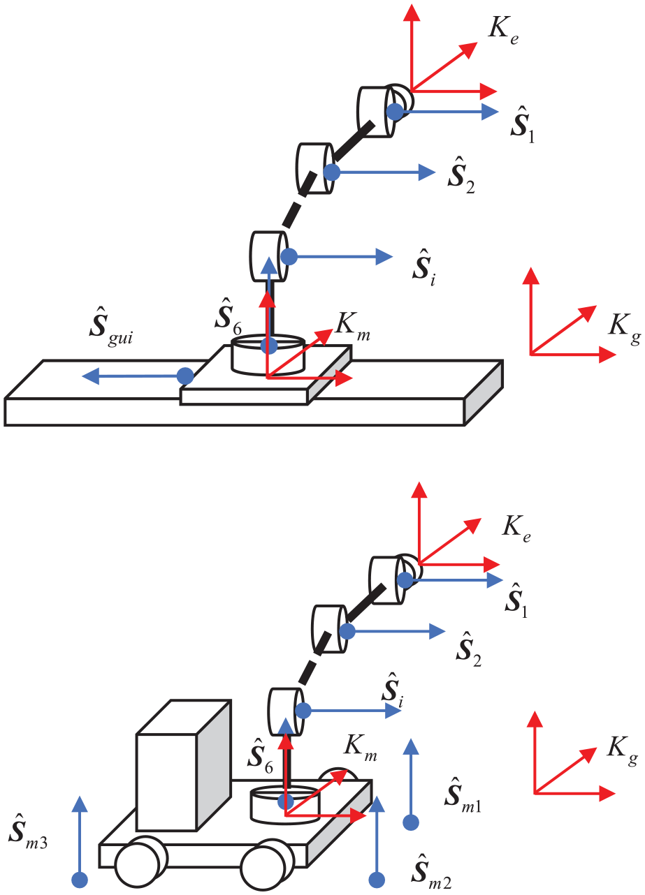
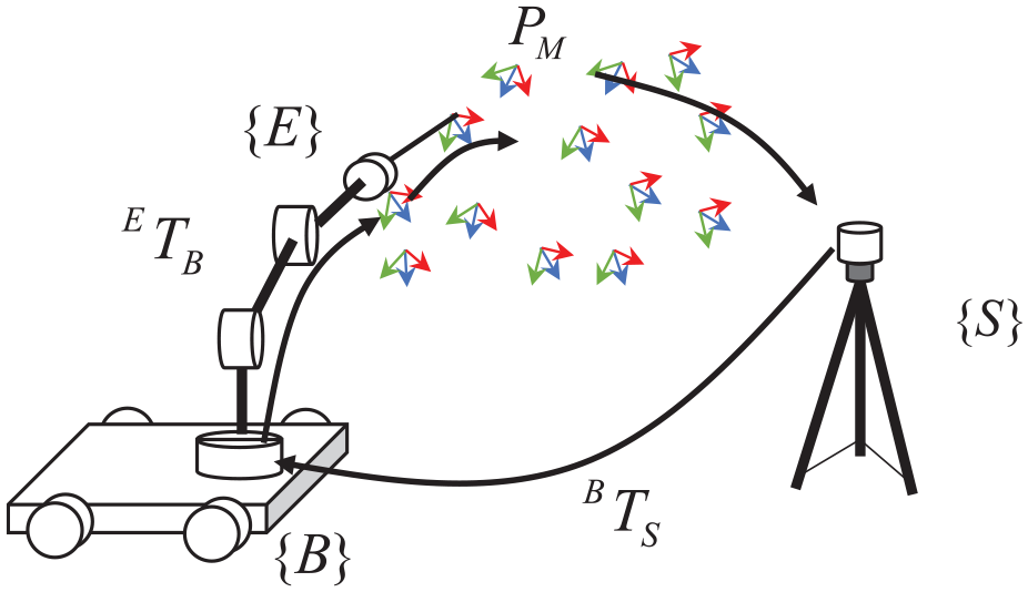
The mobile robot consists of an industrial robot arm and a mobile platform. In order to expand the motion space of robots, a mobile platform is often installed at the bottom of the robot. Due to the introduction of mobile platforms, the mobile robot is with redundant degrees of freedom. In order to describe the mechanism with redundant degrees of freedom conveniently, the screw theorem is used to describe the kinematics model of the mobile robot. The screw theory has a clear physical meaning, simple expression, and can be used for algebraic operation easily. Also, the screw theory can describe the redundant degrees of freedom easily. The robot in series can be considered as an accumulation of motion of each joint screw. The coordinate System Ke is connected to the end effector of the mobile robot, and Km is connected to the centroid of the mobile platform. Both coordinates are parallel to the global coordinate Kg, as shown in Figure 1. The general screw
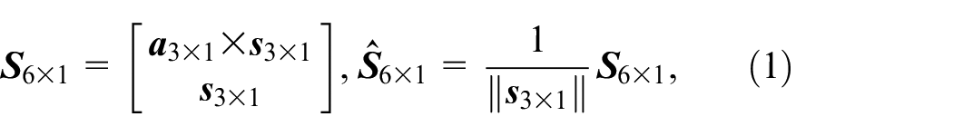
Kinematic model of mobile manipulators with guided-rail and AGV.
For the transition motion, since
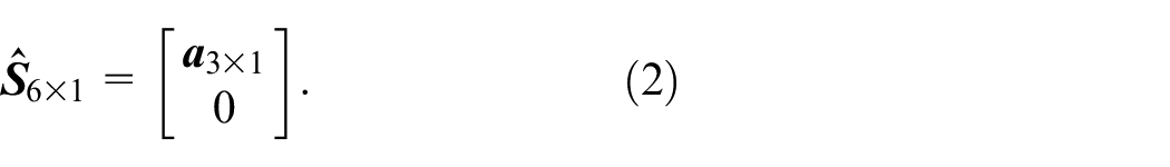
Among them,
Among them, the screw
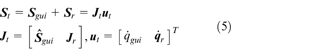
To expand the motion space of the robot, guide rails or mobile platforms can be installed on the robot base. When the robot base is a guide rail, the motion screw of the guide rail is,
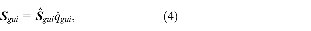
The dynamic model of a guide rail type mobile robot can be written as:
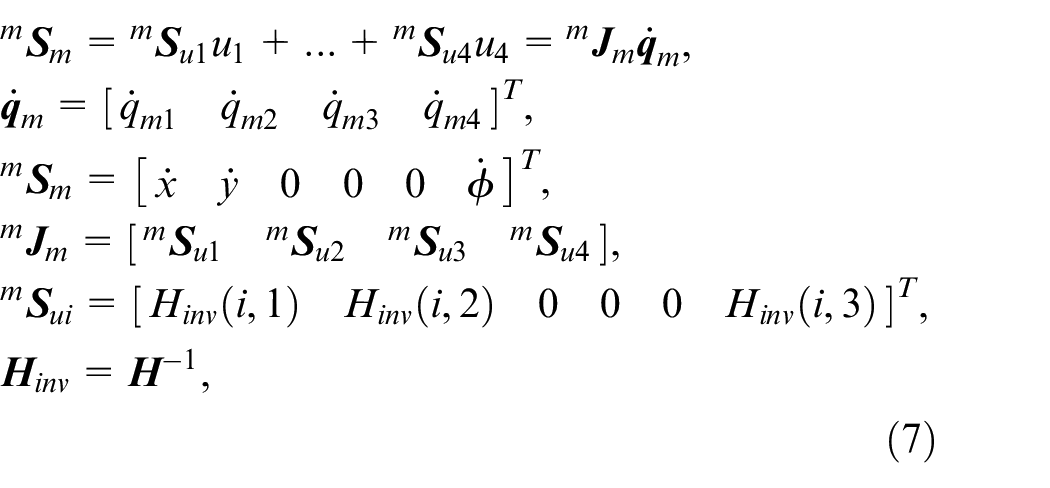
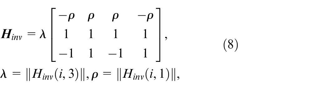
When the robot base is an omni wheel mobile platform, the kinematics model of the mobile platform using Mecanum wheel can be expressed as:
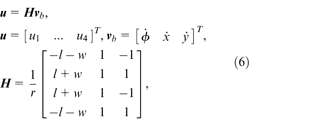
Among them,
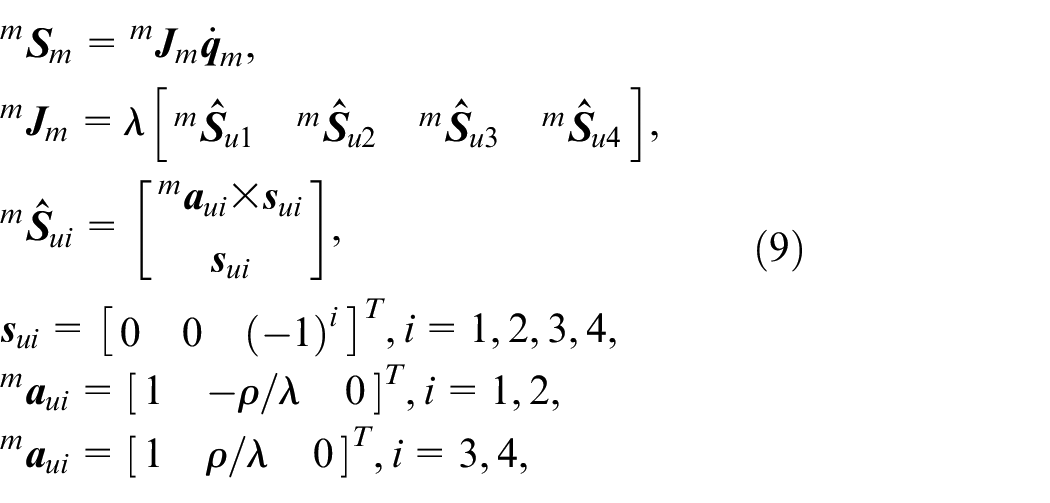
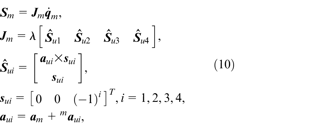
The movement of the mobile platform is located on the mobile base. Therefore, plane motion can be extended to 6-dimensional space.
Among them,
Among them,
Among them,
where
where
Among them,
Collaborative control of multiple mobile robots based on motion screw
To complete complex tasks, guideway robots and mobile robots often reside in the same workspace and complete complex collaborative tasks. Therefore, we propose a multiple robot collaborative motion control method based on motion screw.
Task based trajectory allocation for multiple robots
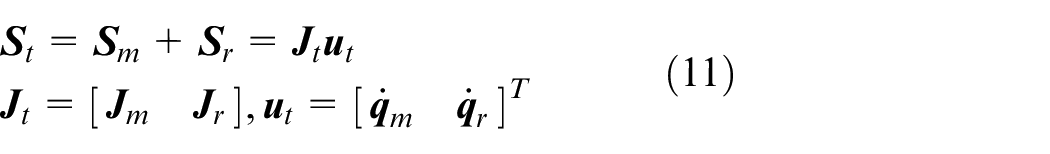
We take collaborative handling tasks as an example. Assuming that the object to be transported is a rigid body, the motion screw of the rigid body is,
The motion screw relative to any point on the workpiece is,
As shown in Figure 2.
Motion screw of rigid bodies.
Due to the rigid contact between each robot and the object,
For each robot, we have
Among them,
When
Hierarchical control of mobile robots
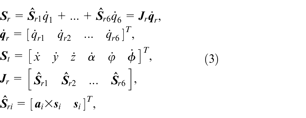
For mobile robots, the Jacobian matrix

among them,
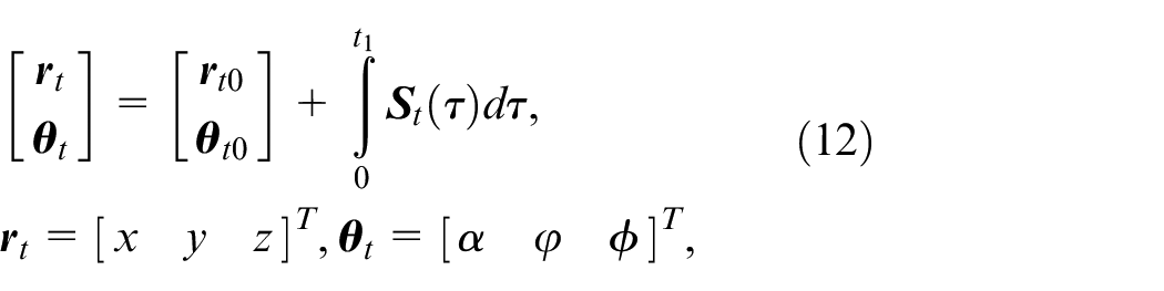
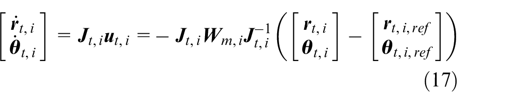
Figure 3 show the motion screw of the mobile robot. By adding the motion screw of the mobile platform, the motion of mobile robot is decomposed as motion of the robot arm and the motion of the platform, which is constraint by the motion of the rigid body. Then, the control objectives of the robot are decomposed into the control objectives of the mobile platform and the control objectives of the robot arm,
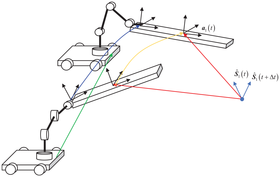
Motion screw of the mobile robot, where the yellow line is the trajectory of the rigid body, the blue line is the trajectory of the end effector, the glue line is the trajectory of the mobile platform.
However, choosing the posture of mobile platforms,
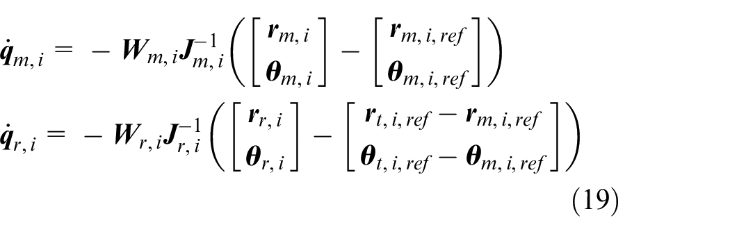
If the workspace of the robot arm covers the desired trajectory, the auxiliary reference mobile platform
If the workspace of the robot arm cannot cover the desired trajectory,
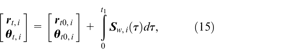
As a summer, the trajectory of the end effector of the mobile robot is calculated through equation (15), while the trajectories of the robot arm and the mobile platform are calculated through equation (19). The flowchart of the collaborative control of multiple mobile robots is given in Figure 4.
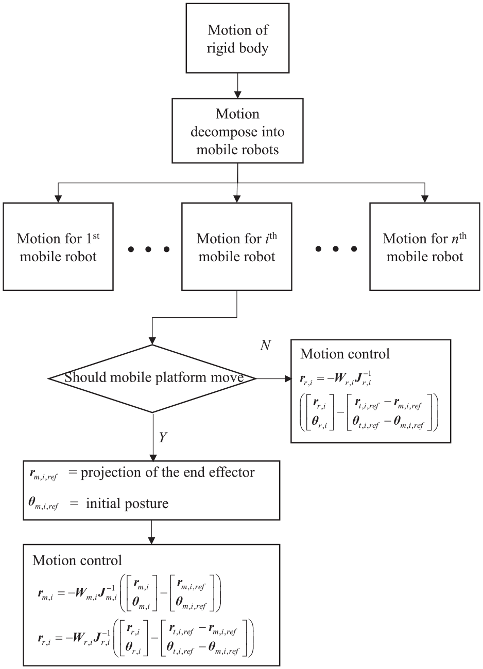
flowchart of the collaborative control of multiple mobile robots.
Stability analysis of the hierarchical control
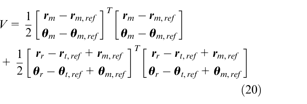
In order to prove the stability of the hierarchical control, the Lyapunov function for the control error of the mobile robot is established,
Taking the derivative of V has
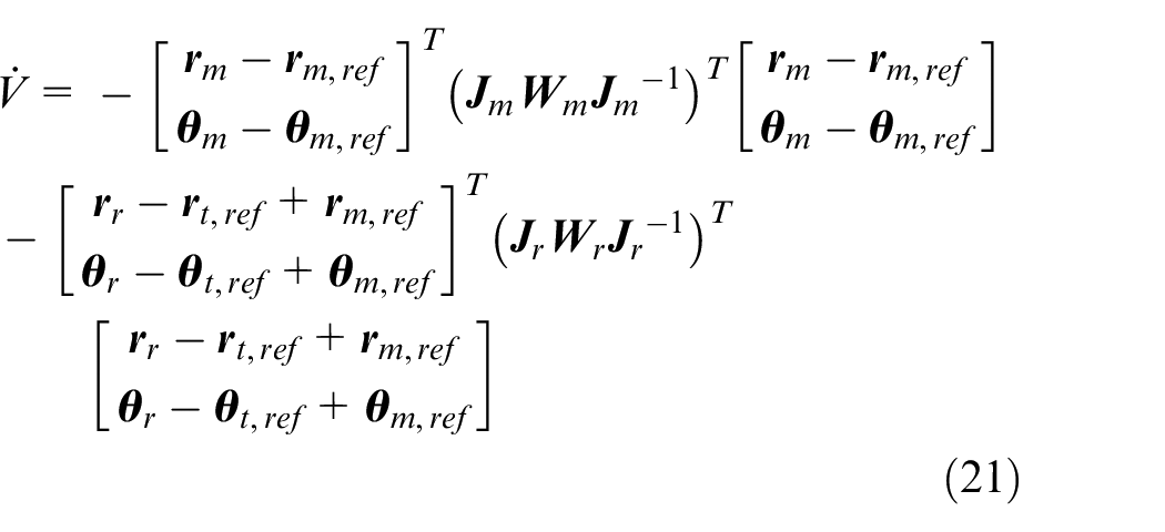
Since the parameter matrix
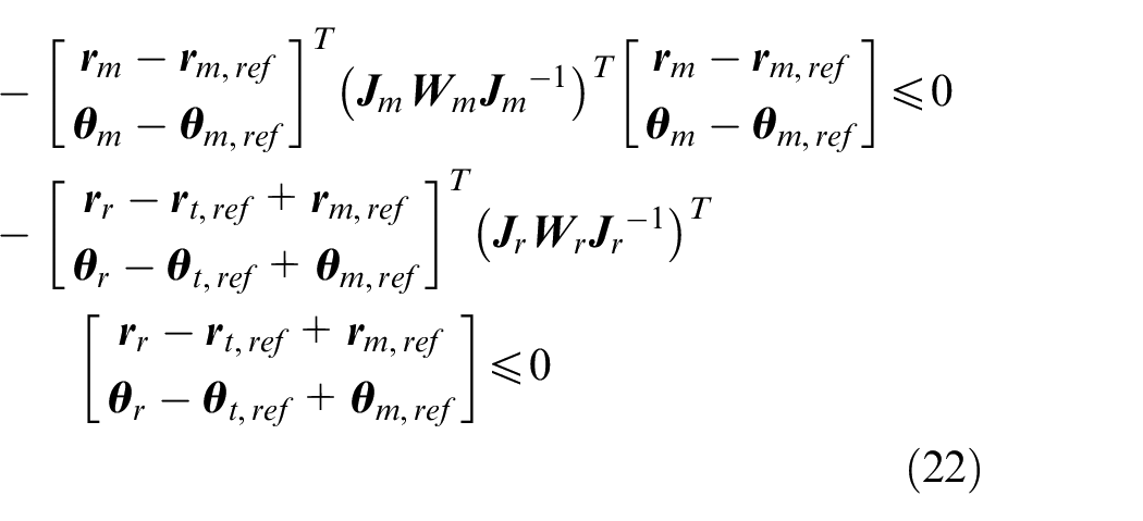
Thus,

The asymptotic stability of the hierarchical control for mobile robot can be proved. Then, the tracking error of the mobile robot approaches 0, we have
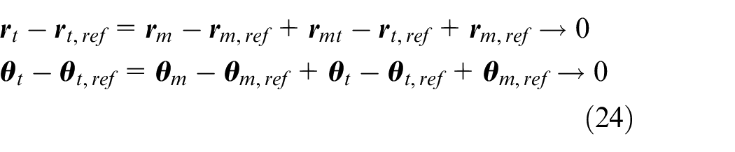
From equation (24), it can be seen that as the error between the mobile platform and the robot arm approaches 0, the error of the end will also approach 0.
Numerical simulation
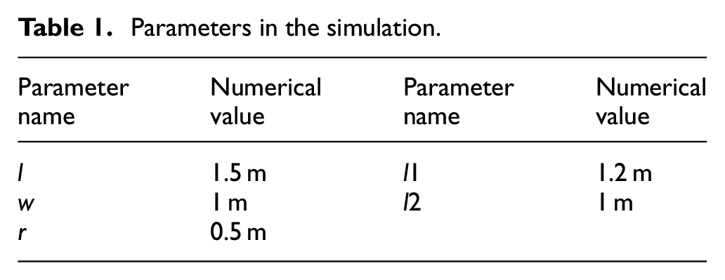
In this part, the hierarchical control of multiple mobile robots is compared with coupling control scheme. The system parameters are shown in Table 1. To simplify the analysis, it is assumed that the center of the mobile platform coincides with the first axis of the robot. In simulation research, control the first three joints of the mobile platform and robot.
Parameters in the simulation.
The robot simulation task is as follows: three mobile robots need to achieve a synchronous motion and a collaborative handling. The ideal trajectory of a known workpiece is,

The trajectory assigned to each robot is,
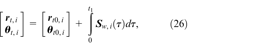
Figure 5 shows the trajectory tracking control results of a robot using integrated control. Due to the redundant degrees of freedom of the mobile robot, the motion of the robot base cannot be directly controlled, and its motion depends on the selection of the control weight parameter
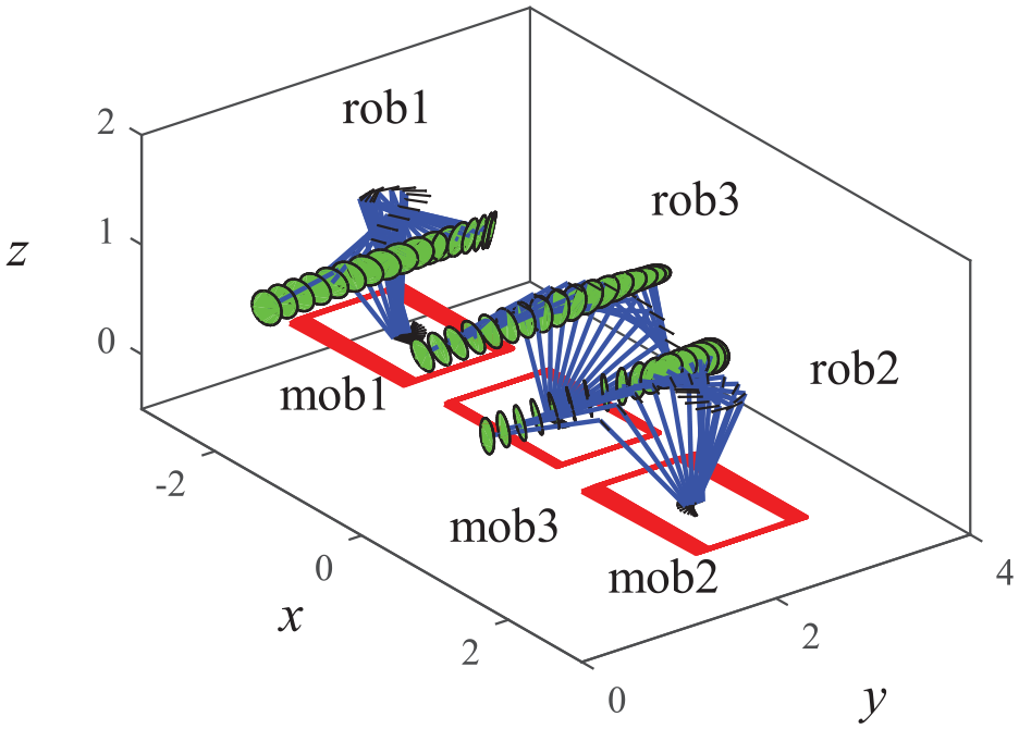
Motion simulation of mobile manipulators under coupling control strategy.
Motion trajectories of mobile manipulators under integrated control strategy: (a) tracking error of the end effectors, (b) synchronous error of the end effectors, and (c) synchronous error of the mobile platforms.
In order to achieve high-precision motion collaboration of multiple mobile robots, the hierarchical control method proposed in this paper is adopted. Due to the need for design in hierarchical control, it is necessary to assist in designing the motion trajectory of the mobile platform. Therefore, based on the robot’s motion trajectory, the ideal motion trajectory for the mobile platform is,

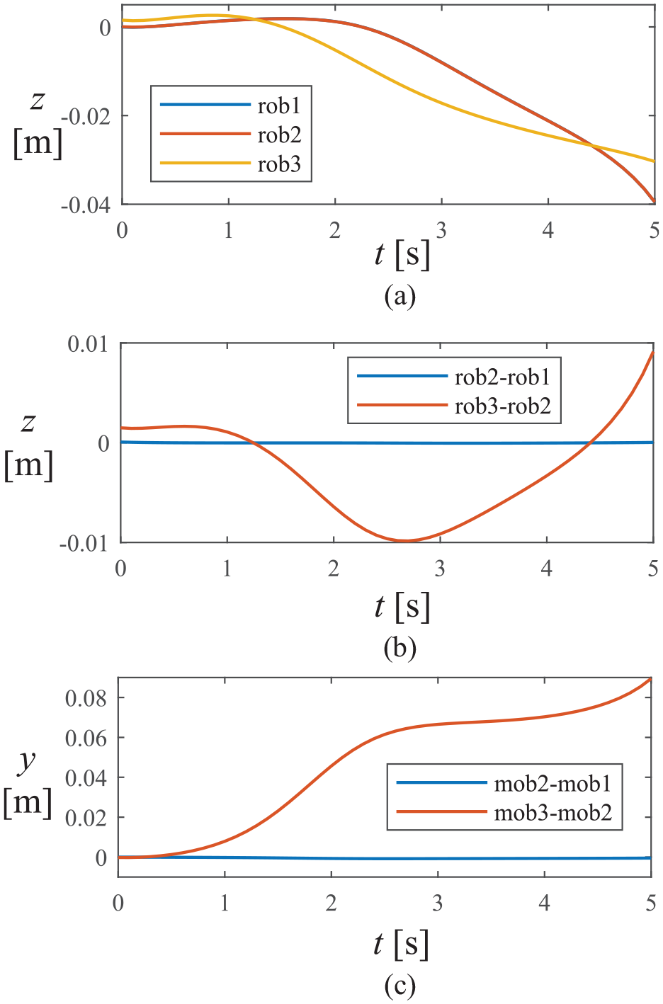
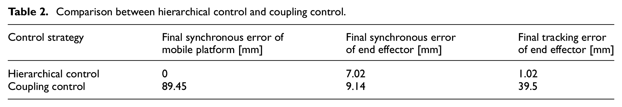
Figure 7 shows the trajectory tracking results of a robot using hierarchical control. Figure 8 shows the analysis of specific robot motion data. Figure 8(a) shows the trajectory of the end effector in z-direction, Figure 8(b) shows the synchronous error within three mobile robots in z-direction. Figure 8(c) shows the synchronous error in y-direction. Due to the constraint of the mobile platform, the mobile platform can ensure smooth motion. Compared to the coupling control method, the collaborative error of end tracking is smaller under hierarchical control mode, and the motion error in the z-direction is within 2 mm. The reason is that by reducing the disturbance of the mobile platform, the motion control of the robot arm can respond faster to errors, thereby achieving better control results as shown in Table 2.
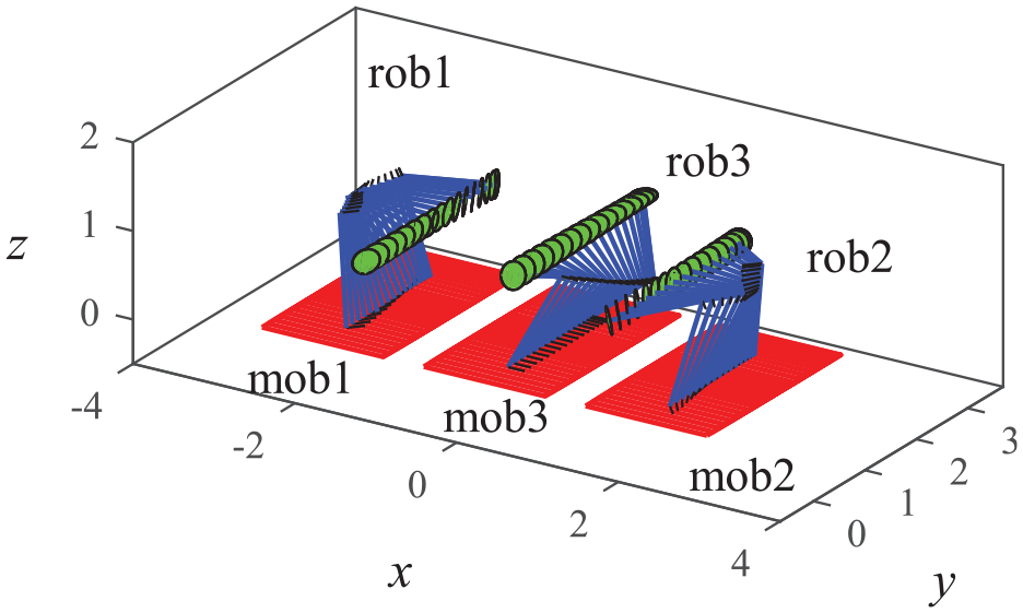
Motion trajectory of mobile manipulators under hierarchical control strategy.
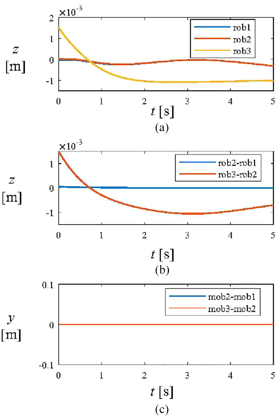
Motion trajectories of mobile manipulators under hierarchical control strategy: (a) tracking error of the end effectors, (b) synchronous error of the end effectors, and (c) synchronous error of the mobile platforms.
Comparison between hierarchical control and coupling control.
Experimental verification and results
We will use a multiple mobile robot system for the assembly task of aircraft skin trusses. The truss is with a length of 3 m. The main function of the long truss is to increase the stiffness and strength of the skin, ensuring the safety of aircraft flight.
A multiple robot collaborative assembly system was built in Shanghai Aircraft Manufacturing Company Co., Ltd. The system consists of three KUKA industrial robots, two of which are installed on rails and one on a mobile platform, as shown in Figure 9. Robot 1 and 2 are KUKA KR210, while robot 3 is KUKA KR60. In order to install the long truss on the wall panel, two robots need to clamp the long truss to ensure its smooth movement. A robot needs to apply glue to the long truss. Therefore, the motion of all three robots is constrained by the long truss. The laser tracker is Leica AT930, which has a precision accuracy 15 + 6 μm/m. To unify multiple robots into the same coordinate system, calibrate the initial position of each robot. Each robot moves a special trajectory, while the laser tracker records the trajectory and calculates the base of each robot.
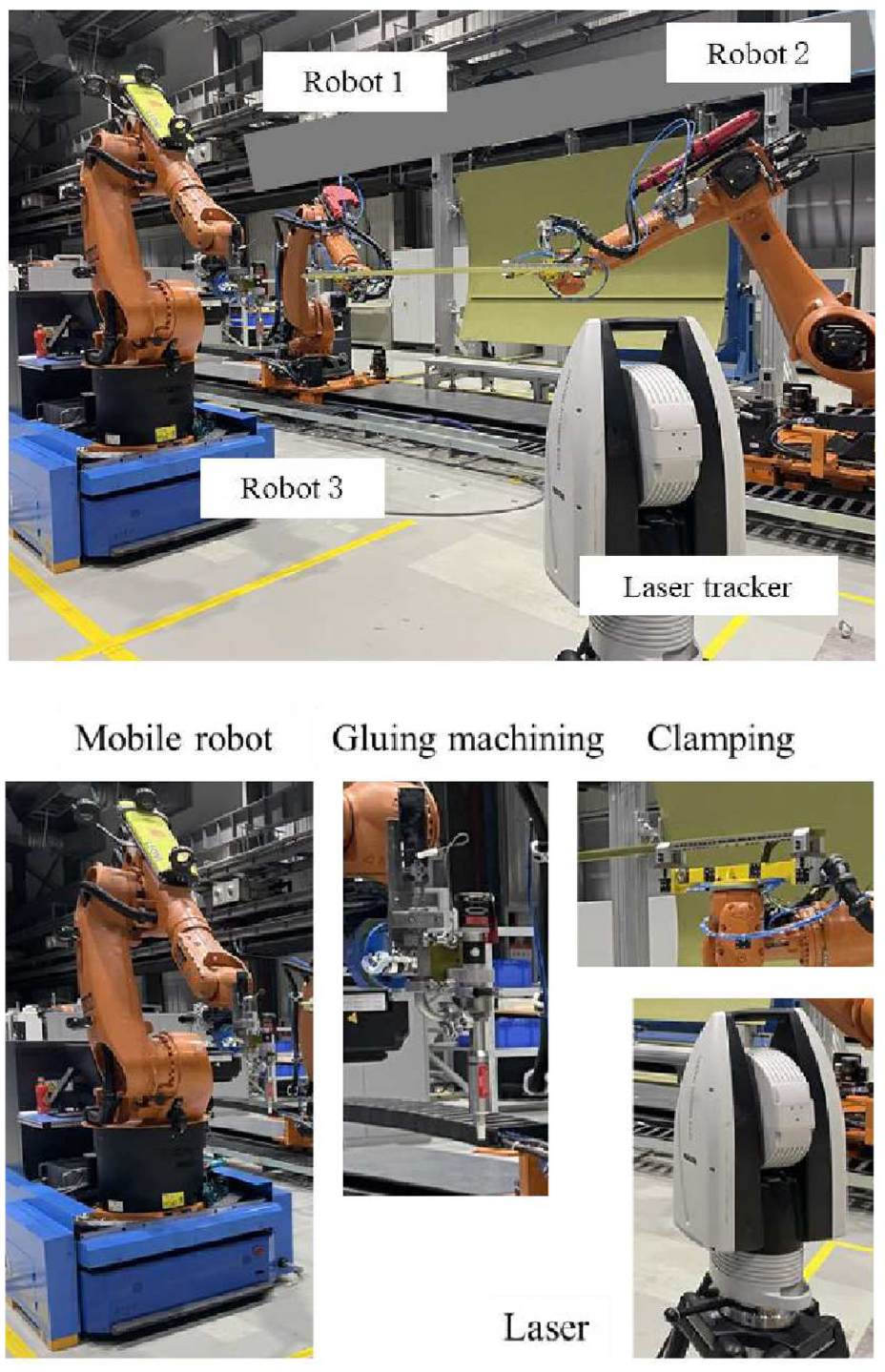
Collaborative multi-robot assembly scenario for aircraft panels.
The detailed experiment steps are given as follows:
Step I: Calibration of the mobile robot system
All robots should be calibrated in the same coordinate. Thus, the robots move in 12 different positions. A mark is attached to the end effector of the robot arm, while the Laser recording the position of the mark in different positions. According to the recorded data, we have a relationship,

where
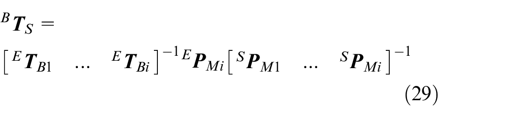
Coordinates of the mobile robot system.
Thus, the base of the robot arm after the motion of the platform is known. Figure 11 shows the measured mark points during the calibration process.
Step II: Control of the multiple mobile robot system
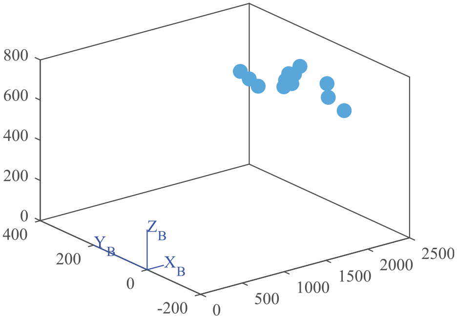
Measured mark points during calibration process.
At the beginning, the mobile platform is controlled to its desired position. The base of the robot arm is calibrated according to the step I. After that, each robot follows its own trajectory. To minimize the cooperate error, robot 2 is following the motion of robot 1, which consists of master-slave system.
The trajectories of the robot and the mobile platform are collected by the laser tracker. Figure 12 shows the motion trajectory of the mobile platform, where all platforms move to the workspace. Figure 13 shows the motion of three robots in the same coordinate. It can be seen that robots 1 and 2 have good motion synchronization, meeting the rigid body motion constraints of the long truss. Since robot 2 follows the motion of robot 1, there is a delay between robot 1 and 2, as shown in Figure 14. After robot 1–2 reaches the designated position, robot 3 gelatinizes the strip along the lateral direction of the strip.
Step III: Assembling aircraft trusses by multiple mobile robots
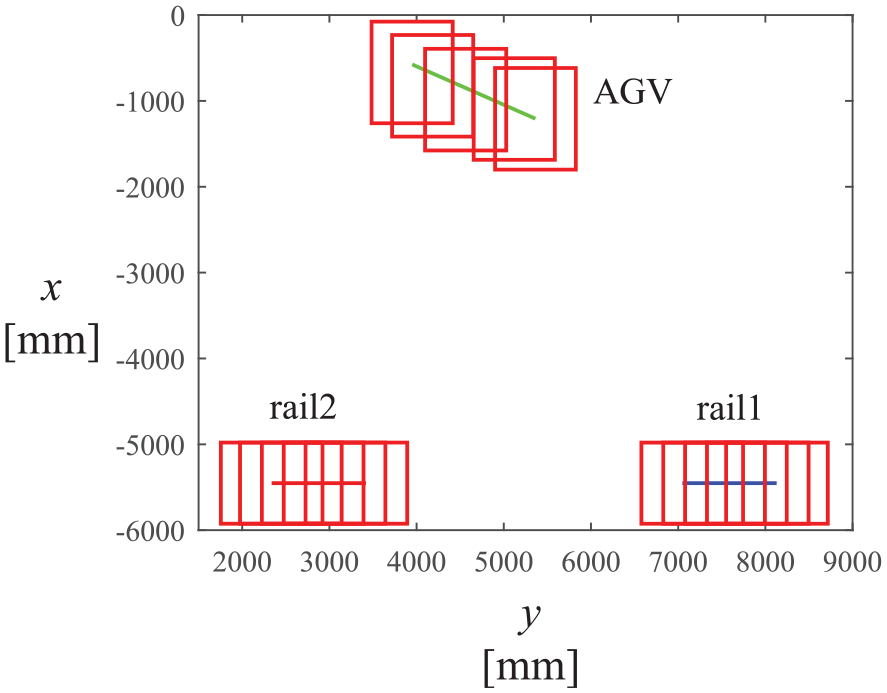
Motion trajectories of three robot bases.
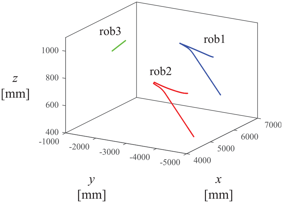
Motion trajectories of three robots.
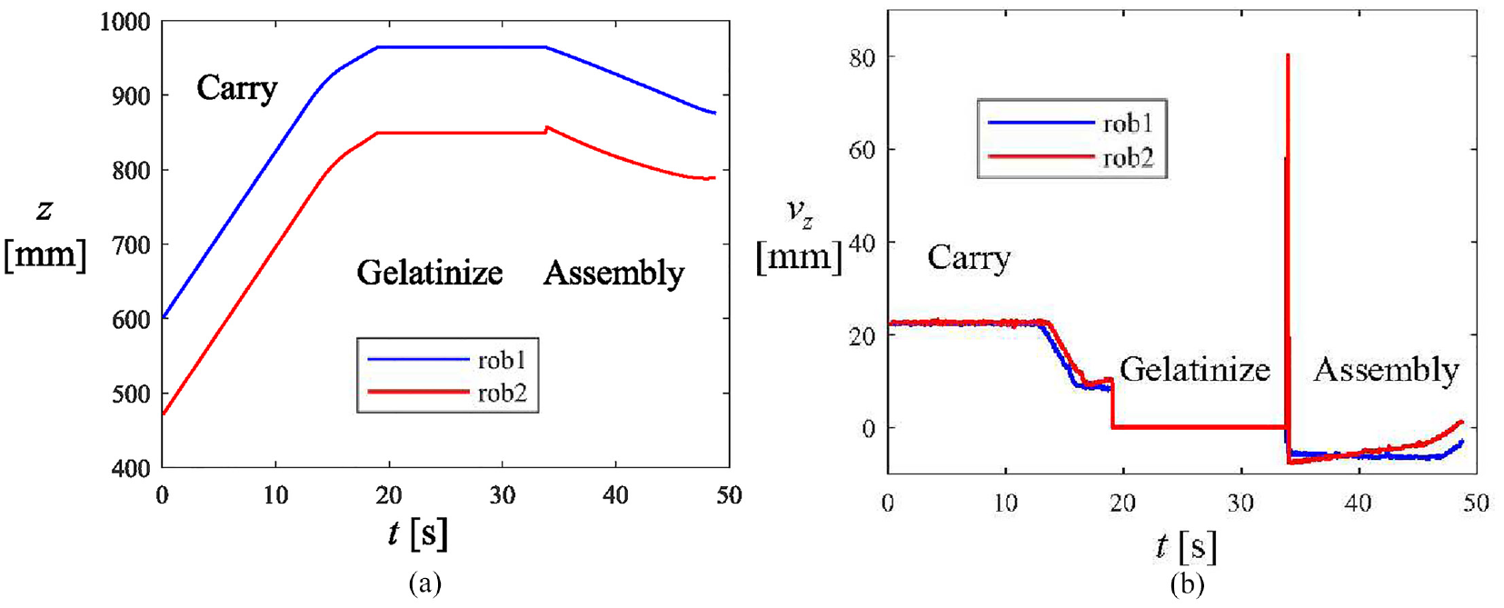
Cooperation motions of robot 1 and 2: (a) the position of both robot in z-direction and (b) the speed of both robot in z-direction.
When the motion trajectories are tested without trouble, the multiple mobile robots are used for aircraft truss assembly. The installation steps for the long truss are as follows: 1. The left and right robots grip the long truss to achieve collaborative handling of the long truss. 2. Lift the long truss flat and use the gluing robot to gelatinize the truss. 3. After the adhesive coating is completed, the long truss is installed onto the skin by a dual robot. Figure 15 shows video recordings of robot motion at different stages. The experiment testifies the possibility of the multiple mobile robot assembly system.
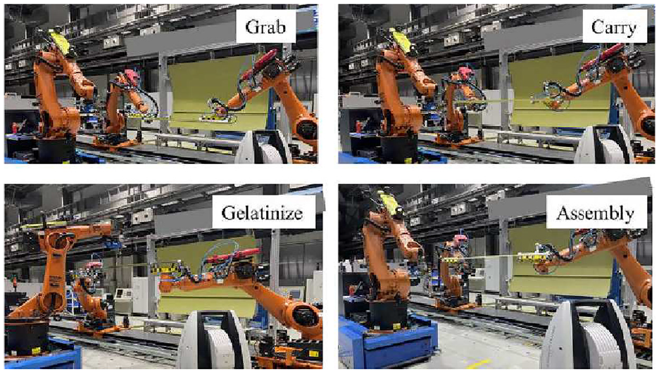
Different task stages of multiple mobile robot assembly.
Conclusion
In order to achieve multiple robot collaborative assembly, this paper proposes a multiple robot hierarchical control method based on motion screw. Firstly, by using the motion screw description method, a mobile robot motion model is established to solve the problem of redundant degree of freedom description for the robot. Secondly, a multiple robot collaborative hierarchical control method is proposed, which decomposes the motion of the mobile robot through the motion of the workpiece. Decoupling robot base motion and robot arm motion is achieved through hierarchical control of the robot arm. Finally, the feasibility of the collaborative control algorithm for multiple mobile robots was verified through numerical simulation and experimental verification. Through the collaborative movement of multiple robots, the long truss assembly of aircraft wall panels has been achieved.
Footnotes
Declaration of conflicting interests
The author(s) declared no potential conflicts of interest with respect to the research, authorship, and/or publication of this article.
Funding
The author(s) disclosed receipt of the following financial support for the research, authorship, and/or publication of this article: This work was supported in part by the National Key Research and Development Program of China under Grant 2022YFB3404102, and the National Natural Science Foundation of China under Grant 52275020, 62293514 and 91948301