
Abstract
Three-dimensional elliptical vibration assisted cutting (3D-EVC) technology has been widely used in many high-precision technical fields due to its high-efficiency processing characteristics. However, the hysteresis and nonlinearity caused by the piezoelectric drive in the 3D-EVC system will impact the system control accuracy. This paper mainly studies the hysteresis and nonlinearity of the system, the feedforward-gray predicted fuzzy PID compound controller based on the generalized Bouc-Wen hysteresis nonlinear model and it is designed to realize the hysteresis compensation of the system. In this paper, input voltage and output displacement are represented by a mathematical relationship, and this relationship of the 3D-EVC system will be described by the generalized Bouc-Wen model. The improved flower pollination algorithm (IFPASO) is adopted in the identification process of parameters. A compound control strategy is formed based on traditional feed-forward control combined with fuzzy PID feedback control to compensate for hysteresis and nonlinearity, and an improved gray prediction model is introduced into the feedback loop. The 3D-EVC system tracking experiment verifies the effectiveness of the designed compound controller. Experiments have proved that the hysteresis component of the system is significantly reduced after the use of the compound controller for hysteresis compensation, and the system has a higher degree of stability.
Keywords
Introduction
With the constant progress in ultra-precision processing manufacturing technology and the emergence of new challenges in the processing industry, 3D-EVC technology has been widely studied since it was first proposed by experts and scholars in 2005. 1 Based on the development of traditional one-dimensional and two-dimensional elliptical vibration assisted cutting, 3D-EVC represents a novel type of ultra-precision cutting technology that is clearly advantageous in improving the quality of processed surface, reducing cutting force, and optimizing the processing device.2–5 Despite some in-depth research on network control, 6 tracking control,7,8 and hysteresis compensation of nonlinear systems,9,10 there are still few studies conducted on the hysteresis compensation of 3D-EVC systems
As an important variety of functional material, piezoelectric ceramics possess excellent electrical properties, which makes them widely applicable in various high-tech fields. Therefore, some experts have analyzed the inherent piezoelectric hysteresis characteristics of piezoelectric ceramic materials and carried out related research. Based on the hysteresis model, an accurate system model is established to carry out the related research. In addition, Al Janaideh et al. 11 constructed a model to demonstrate that nonlinearity is shown by the piezoelectric actuator of hysteresis. The studied model takes into account the geometric and inertial nonlinear beams. Ma et al. 12 proposed a hybrid intelligent hysteresis model (HIHM).
Regarding the compensation control strategy that accommodates the hysteresis characteristics of the system, scholars tend to adopt the most suitable control strategy according to the differences of the system under study, such as adaptive sliding mode13–16 and PID feedback control strategy.17,18 As controlled objects become diversified and complex, higher-order control strategies are increasingly applied. Jian et al. 19 proposed a new control strategy that combines iterative learning control (ILC) with hysteresis direct inversion to compensate for the nonlinearity and uncertainty of the system. Also, an output feedback controller was proposed by Salah and Saleem, 20 which has a certain lag in dynamic compensation. Wang et al. 21 presented a security control strategy which can be used to effectively address the singularity of the adaptive iterative process as encountered in the existing studies. The proposed control strategy theoretically enables the system to achieve the optimal output effect.
Finally, the proposed control strategy is verified through simulation of the electromechanical power system, 22 and the three-dimensional elliptical trajectory of the tool synthesized by the control system can be processed. According to the experimental results, this machining method achieves a better-cutting performance than traditional continuous cutting (TCC) and two-dimensional elliptic vibration cutting (2D-EVC) methods. 23
In summary, there have been related research carried out on piezoelectric hysteresis modeling and compensation systems for the inherent hysteresis nonlinearity. However, there are still few studies conducted on the hysteresis nonlinearity due to piezoelectric driving in three-dimensional elliptical vibration assisted cutting.
The remains of this paper are arranged as follows: a piezoelectric hysteresis model based on the 3D-EVC system is established in Section “Piezoelectric hysteresis modeling of 3D-EVC system”; Section “Compound controller of 3D-EVC system based on piezoelectric hysteresis model” proposes a 3D-EVC system composite control strategy based on the piezoelectric hysteresis model; experiments based on the composite control strategy verification is performed in Section “Simulation and experimental result”; and some summative comments are given in Section “Summary and conclusion.”
Piezoelectric hysteresis modeling of 3D-EVC system
The 3D-EVC device relies on the internal piezoelectric stack to drive three axial flexure hinges denoted as Y1, Y2, and Z, respectively. Through the phase difference between the three driving signals, the motion of the tool tip leads to a three-dimensional elliptic trajectory. The piezoelectric stack of 3D-EVC is comprised of piezoceramics materials, whose inherent hysteresis and nonlinearity impede the system from outputting an ideal three-dimensional elliptical trajectory according to a specific input. In the 3D-EVC system, the relationship between the input voltage and output displacement is described using the Bouc-Wen hysteresis model. In the present study, the complex hysteresis occurring in the 3D-EVC system is accurately described by this model, as required to establish a high-precision theoretical model for the design of subsequent composite control strategies.
Bouc-Wen model
The earliest proposal of the Bouc-Wen model was used to represent the early practical hysteresis model with high accuracy for simulating metal dampers. Bouc-Wen models have been widely used to explain nonlinear phenomena in fields like civil, mechanical, etc. 24
The mathematical expression of the Bouc-Wen model can be expressed by equation (1):
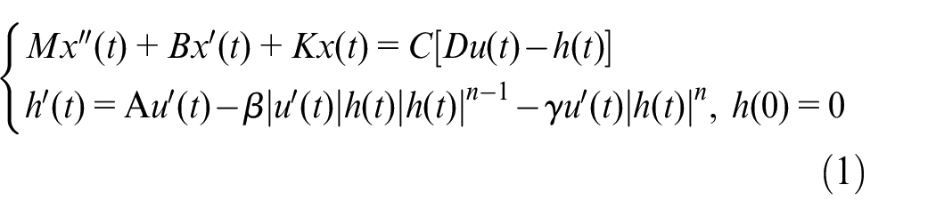
Under normal processing conditions, the three-phase drive is a low-frequency input, therefore, the
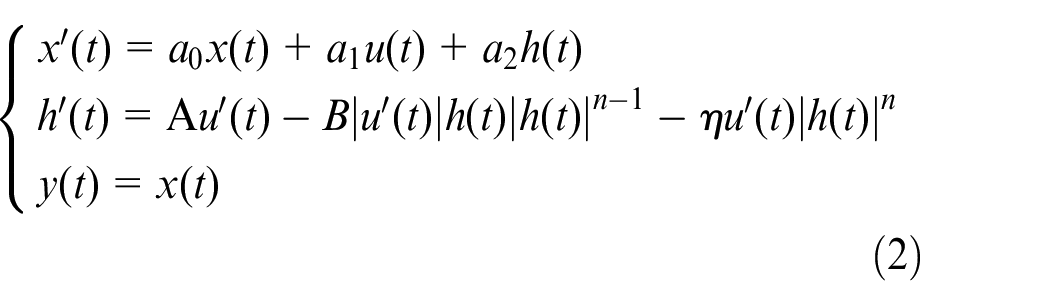
We can see from equation (2) that for getting the complete Bouc-Wen model which can represent the hysteresis characteristics of the 3D-EVC system. Parameters
Improved flower pollination algorithm
As an emerging swarm intelligence optimization algorithm, flower pollination has been applied in recent years to resolve the relevant practical problems. 25 According to this algorithm, the optimization is conducted in two step: One is global pollination and the other is local pollination.
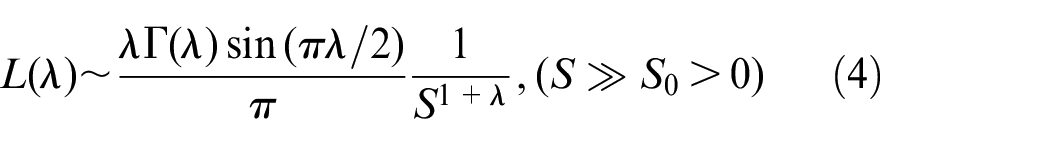
In the global pollination procedure, equaiton (3) is used to represent the global pollination of flowers:

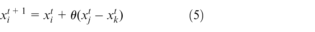
The local pollination could be represented by equaiton (5):
To determine the parameters of the Bouc-Wen model of equaiton (2), improve the accuracy of algorithm identification, and solve the problems of traditional parameter identification algorithms, the traditional problems such as poor optimization ability and falling into optimal local values easily. This paper proposed an improved flower pollination algorithm (IFPASO) which was based on particle swarm optimization.
Poli et al. 26 introduce particle swarm optimization (PSO) to compensate for the randomness of the primary solution in the incipient stage in FPA. It is divided into two portions in the implementation process of IFPASO. One executes PSO, the other executes FPA. This method can improve the ability of the algorithm to find the optimal solution and the convergence speed of the algorithm.
In the traditional FPA execution stage, the local and global searches are tuned with a fixed probability value
Model parameter identification
For identifying the unknown parameters contained in the model, to accurately describe the performance of the system. By giving a sinusoidal excitation signal
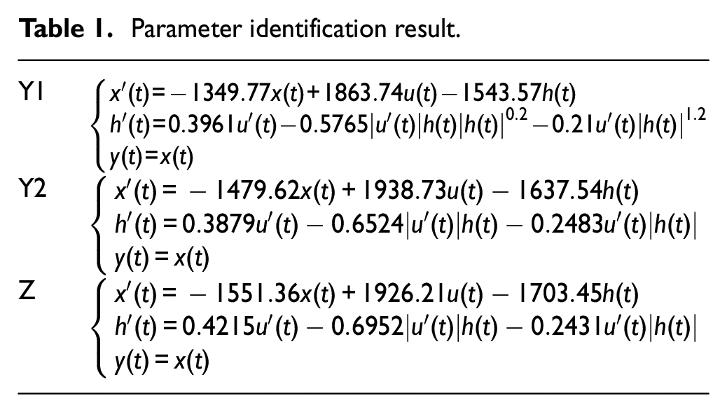
The Bouc-Wen model of the system obtained by identification is shown in Table 1.
Parameter identification result.
Compound controller of 3D-EVC system based on piezoelectric hysteresis model
Feed-forward compensation control strategy
The organized model is shown in equaiton (1). The model only needs to calculate the compensation voltage of the hysteresis component, and then voltage compensation can eliminate the hysteresis. While removing the complex process of establishing the inverse model, it also improves the accuracy of control and linearization.
Assuming that the input voltage of the feed-forward control is


By equaitons (7) and (8) sorted out:

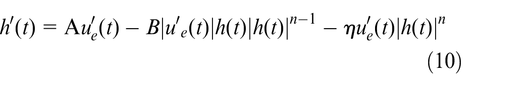
From equation (9) we can see that if we want to find
Via using equation (11) to calculate
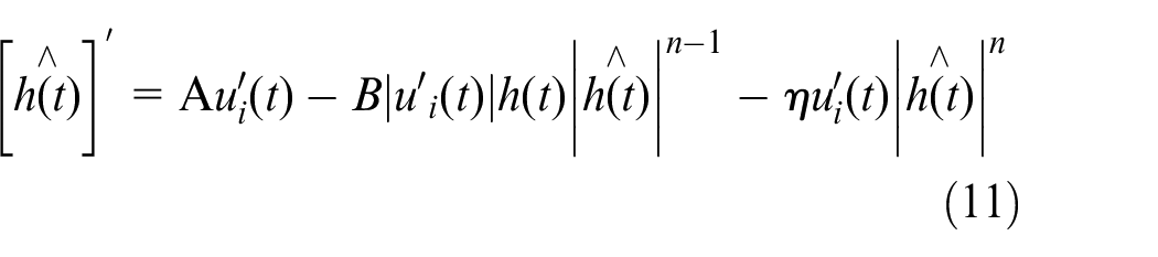
From equations (9) and (11), the expression of
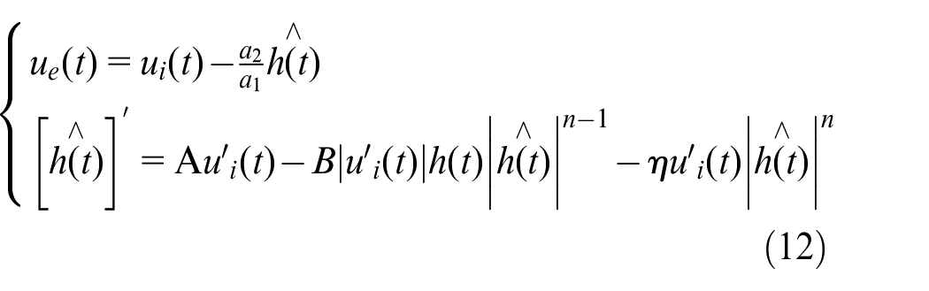
In the calculation process, we can know that the error of the approximate substitution method comes from the hysteresis part of the model expression. After processing by the feed-forward controller, the displacement produced by the entire device is:

In summary, we can get the system error as:
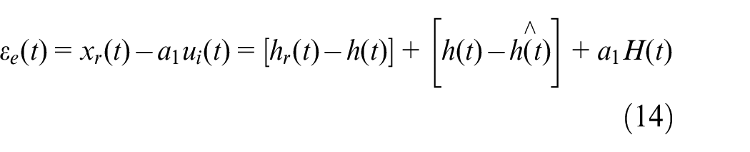
It can be seen from equation (14) that the error
Compound compensation controller
It can be seen from the previous chapter that there is an error in the feed-forward control, which will cause the feed-forward control strategy to not be able to completely compensate for the hysteresis component generated by the piezoelectric stack inside the 3D-EVC device. Therefore, this chapter will propose a fuzzy PID control strategy based on improved gray prediction, and combine it with feed-forward control to form a compound controller that can better compensate the piezoelectric hysteresis and improve the system control accuracy.
Adaptive fuzzy PID control strategy
Adaptive fuzzy PID control is a method that can dynamically adjust PID control parameters.27,28 It makes full use of the operator’s prior experience, and avoids the acquisition of the mathematical model of the object which is controlled. Control parameters can be adjusted by the state of the object which is controlled. The fuzzy adaptive PID controller takes the error
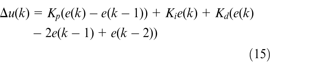


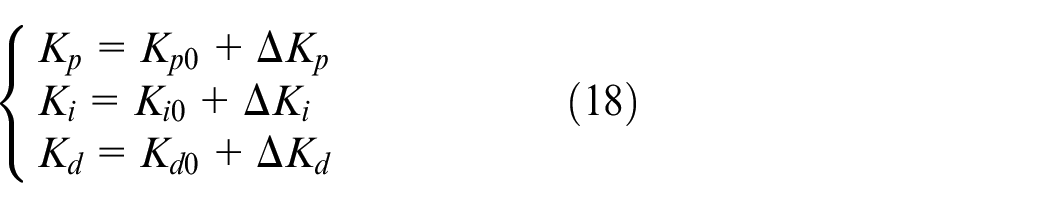
The PID parameter correction calculation formula is as follows:
On the basis of actual control requirements and control precision requirements, the domains of
The membership function table is shown in Figure 1:
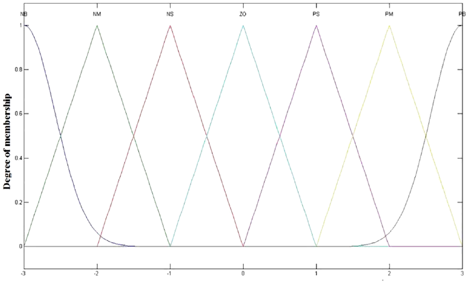
The membership function.
Through the system output characteristics of
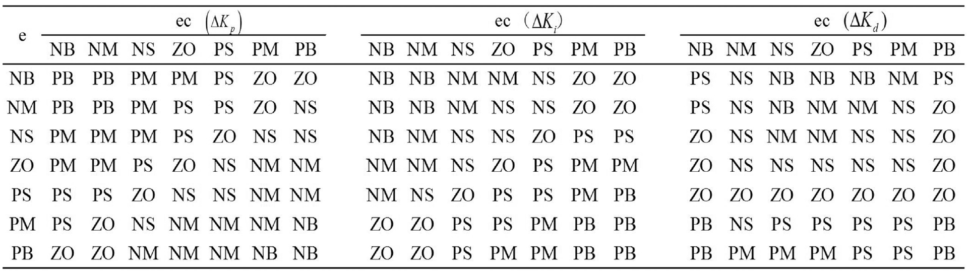
Fuzzy rule table.
Dynamically adjusted gray forecasting model
Since Professor Deng first put forward a set of gray system theories in 1982, as a significant part of the gray system theory, it has been widely used in daily life and social research.29,30
As the core and foundation of gray prediction theory, GM(1,1) model has been fully and widely used. Therefore, the paper chooses GM(1,1) as the basis of the theoretical model. The derivation process of the specific structure of the GM(1,1) model is as follows:
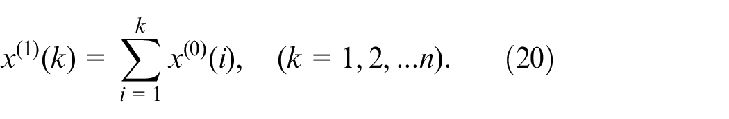
The establishment of the generated sequence: for reducing the randomness of the original data sequence and preparing for the subsequent process, this department uses cumulative generation (AGO) to construct the generated sequence. Let the original sequence by:

Let the one-time cumulative generation (1-AGO) generation sequence be
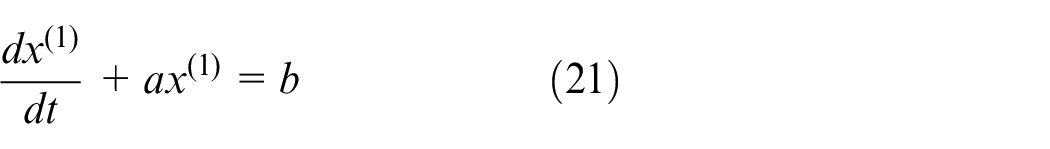
Model establishment: A first-order linear differential equation is established for the generated sequence of
When the data is in discrete form, there are:
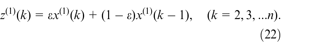
The basic form of the GM(1,1) model can be obtained by sorting the above formula:

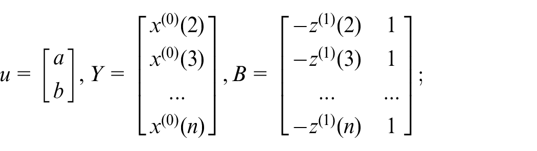
Model parameter estimation: introducing matrix:
Therefore, the GM(1,1) model can be expressed as the following equation:

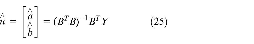
We can obtain the unknown parameters
The discrete form of the first-order linear differential equation is:
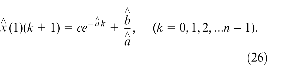
where
Let
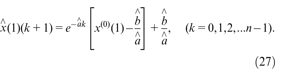
Perform a cumulative reduction (AGO-1) of the above equation to get the predicted value of the original data sequence
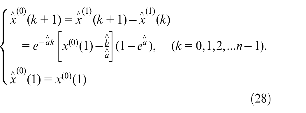
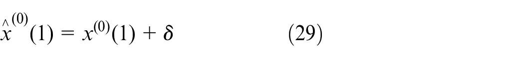
It can be seen from the construction and derivation process of the traditional gray prediction model that it has certain limitations. For example: For the initial value selection problem, when solving the differential equation, assuming
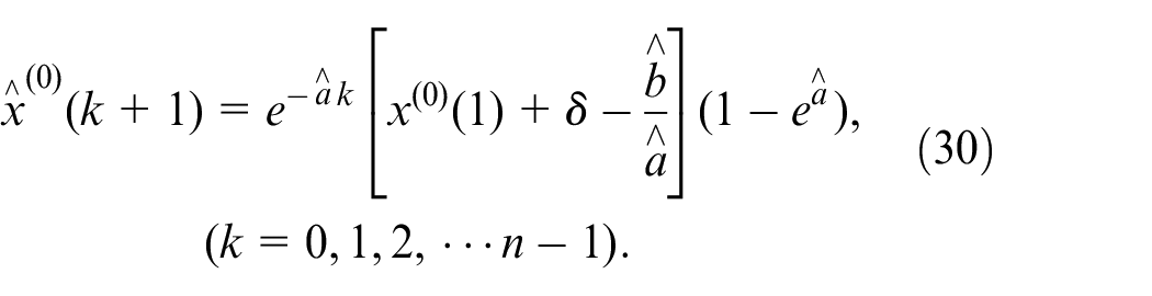
In response to this defect, this paper chooses to add the correction factor
At this time, the predicted value expression of the original data sequence
3D-EVC system compound control strategy
It can be seen from the first two sections, the Bouc-Wen model is constructed on the basis of the 3D-EVC device characteristic, so it should be designed with the 3D-EVC system as the control object.
Due to the existence of interference in the actual environment, pure feed-forward control only compensates in advance for the piezoelectric hysteresis characteristics of the system. To improve control accuracy, this paper constitutes a compound controller by combining feedback control based on feed-forward control. Fuzzy PID control is a kind of “post-control.” Due to the existence of system inertia, this kind of control method is difficult to achieve real-time control in most cases and has a certain delay, so the control quality is limited. This paper will add the improved gray prediction model in the previous section on the basis of fuzzy PID control to improve the control level to reach a higher stage.
Based on the design of the above strategy for control, the functional block diagram of the compound control strategy for the hybrid drive system is shown in Figure 3.
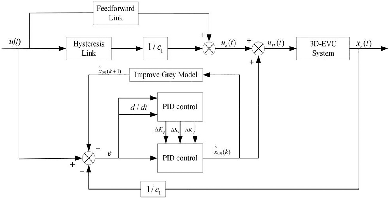
Functional block diagram of the compound controller.
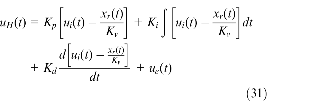
The voltage obtained after performing compound control on the system is:
Simulation and experimental result
Experimental setup
The 3D-EVC system mentioned is compensated by the compound controller designed in the previous section and verified experimentally in this paper. Experimental verification takes the 3D-EVC device shown in Figure 4 as the research object, and the experimental platform shown in Figure 5 is used for testing. By setting the expected trajectory for the three axial subsystems, the PC is used to control the NI controller, the power amplifier is applied to the device, and finally, the data is returned to the PC through the displacement sensor to form a closed loop at the end. The actual output trajectory is collected to verify the effectiveness of the designed compound controller.
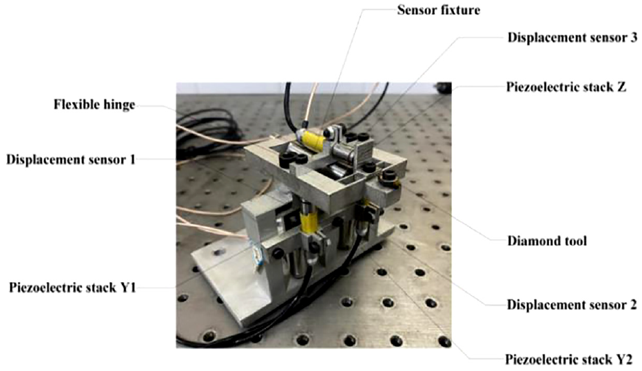
3D-EVC structure.
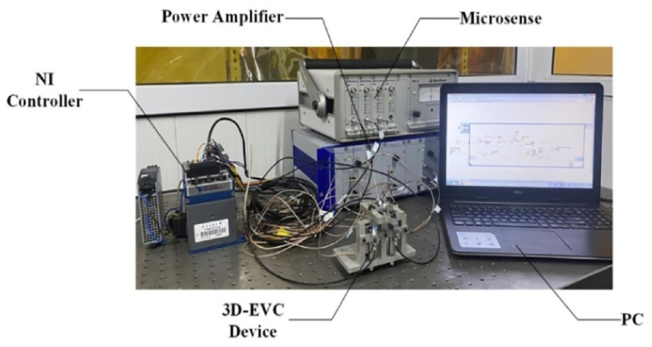
Experimental apparatus.
Experimental results
Figures 6 to 8 show the performance of various axial subsystems in the 3D-EVC system under the action of the compound controller, when a given drive signal is excited, the system responds to the performance of the output trajectory of the excitation signal.
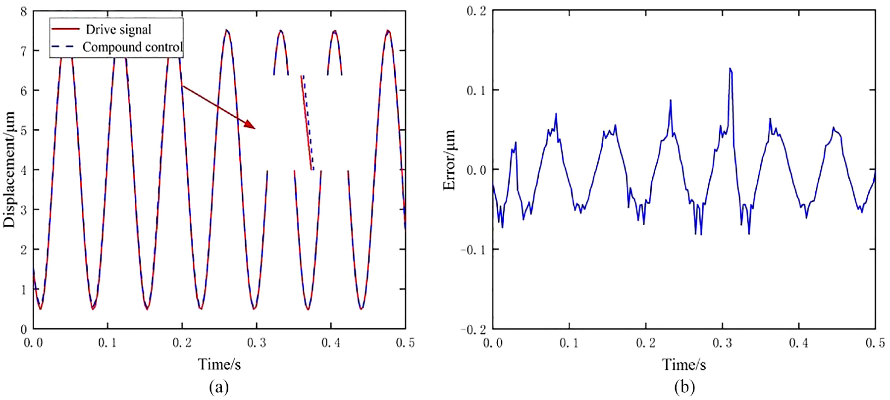
Displacement tracking curve and error of Y1 axial subsystem: (a) displacement tracking curve of Y1 and (b) displacement tracking error of Y1.
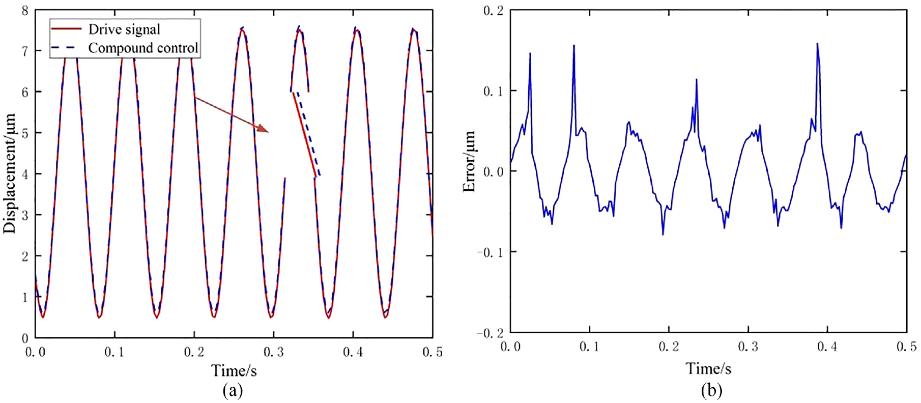
Displacement tracking curve and error of Y2 axial subsystem: (a) displacement tracking curve of Y2 and (b) displacement tracking error of Y2.
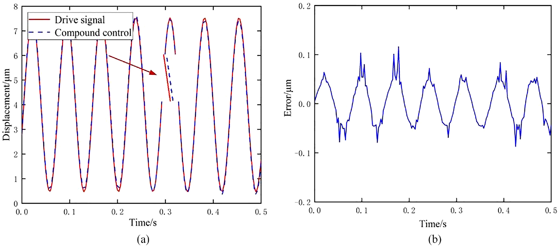
Displacement tracking curve and error of Z axial subsystem: (a) displacement tracking curve of Z and (b) displacement tracking error of Z.
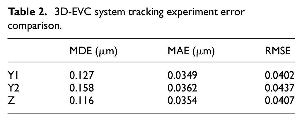
In order to express the experimental data more clearly, the Maximum Displacement Tracking Error (MDE), two methods will be used to estimate the three axial subsystems under the compound control tracking experiment effect, one is the Mean Absolute Error (MAE) and the other is the Root Mean Square Error (RMSE). Through the analysis of the experimental results of compound control, it can be concluded that the system has high displacement tracking accuracy and system control effect. The calculation results are shown in Table 2. The maximum displacement tracking error between the input and output of the three axial subsystems of Y1, Y2, and Z is respectively 0.127, 0.158, and 0.116 mm. The system output has a higher tracking performance for a given input excita-tion signal.
3D-EVC system tracking experiment error comparison.
Figures 9 to 11 show the hysteresis of the 3D-EVC system after using the compound controller to compensate for the hysteresis of the system. It can be seen from the above figures that after the compound controller performs the hysteresis compensation for the system, the hysteresis nonlinearity of the system is significantly reduced, which effectively overcomes the impact of the hysteresis nonlinearity caused by the piezoelectric drive on the system. The effectiveness of the involved compound controller will be further verified in the compensation of system hysteresis and nonlinearity.
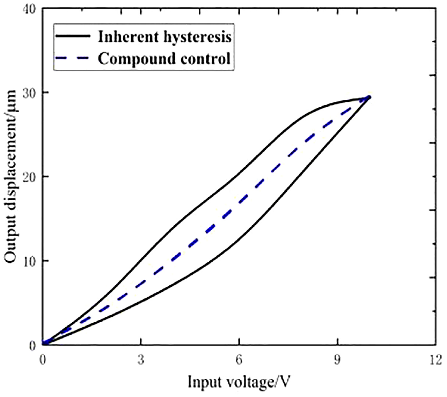
Hysteresis performance of V1 axial subsystem under the compound controller.
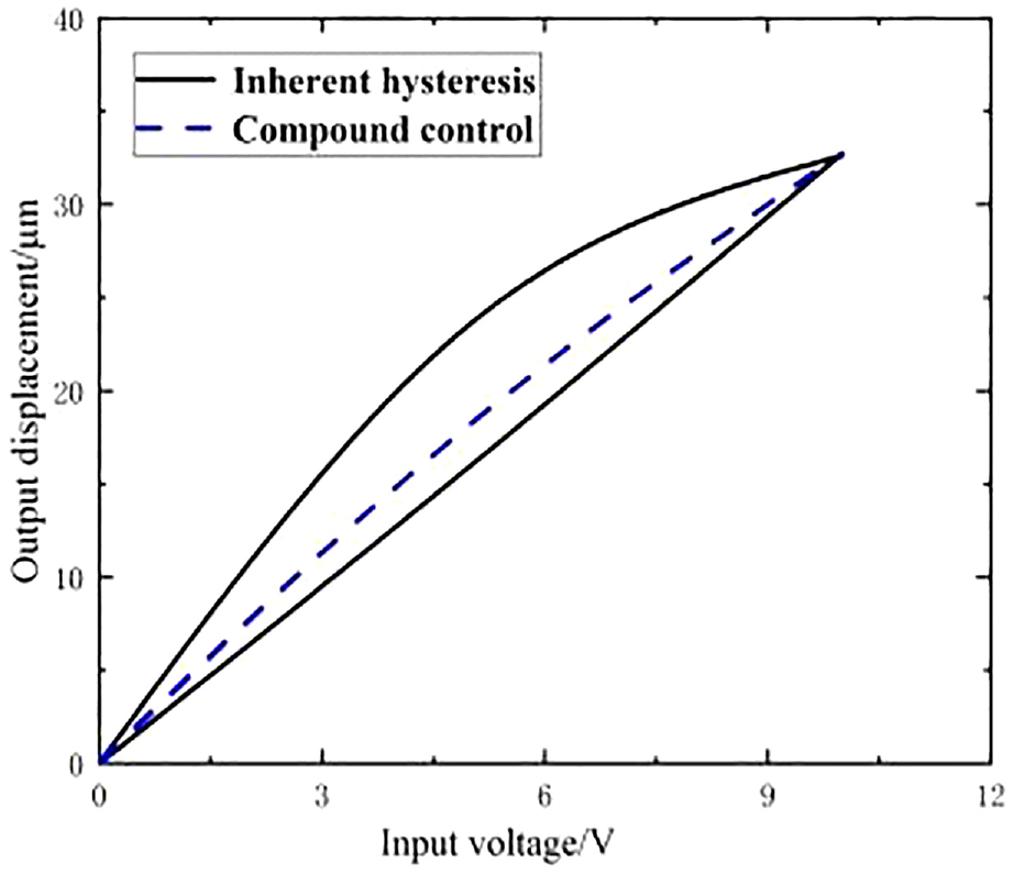
Hysteresis performance of V2 axial subsystem under the compound controller.
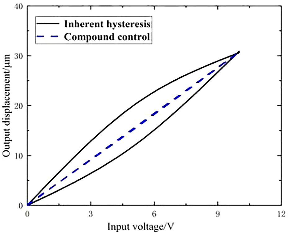
Hysteresis performance of Z axial subsystem under the compound controller.
Figure 12(a), (b), (c), (d) shows the output of three-dimensional elliptical posture trajectory from the system after hysteresis compensation and the elliptical posture trajec-tory obtained under each axial projection. It can be found out that the system with hysteresis compensation performs well in satisfying the elliptical trajectory required by the non-resonant 3D-EVC technology.
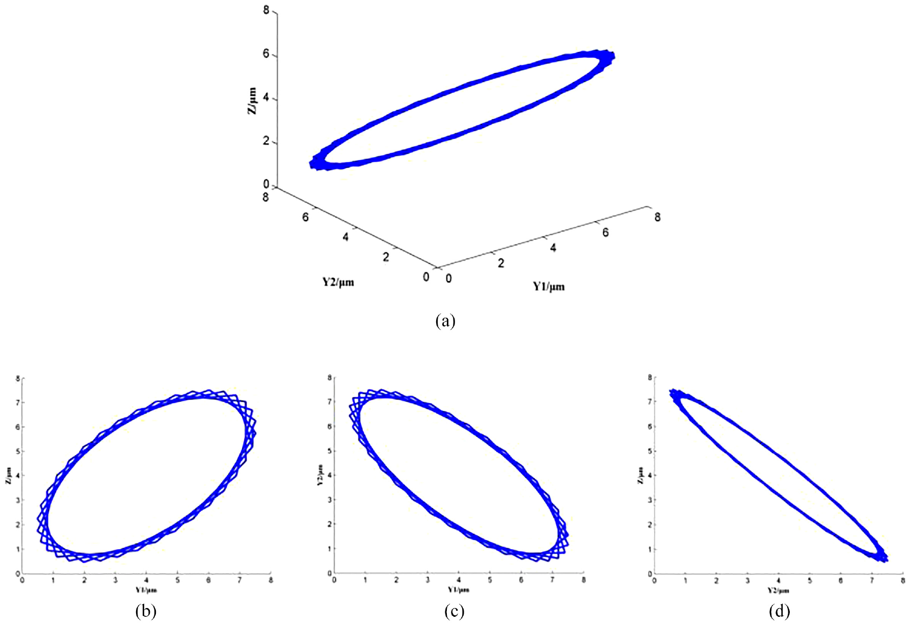
Three-dimensional elliptical posture trajectory: (a) Axial projection of Z axis, Y1 axis, Y2 axis, (b) Axial projection of Z axis, Y1 axis, (c) Axial projection of Y1 axis, Y2 axis and (d) Axial projection of Z axis, Y2 axis.
Summary and conclusion
Piezoelectric ceramic materials are characterized by hysteresis and nonlinearity, which have a significant effect on the performance of the 3D-EVC system and the output of the three-dimensional elliptical trajectory. Through an analysis conducted in this paper on the characteristics and mechanism of the hybrid driven 3D-EVC system, the hysteresis and nonlinearity of the 3D-EVC system are explored. The main contributions of this paper are as follows:
(1) On the basis of the 3D-EVC system analysis, the generalized Bouc-Wen model is applied to demonstrate the hysteresis and nonlinearity of the system. To improve the accuracy of parameter identification by the model and enhance the performance of the algorithm, the traditional algorithm of flower pollination is improved. Firstly, the particle swarm algorithm is applied to accelerate the optimization process, and the self-adjusted conversion probability is introduced to improve the search ratio and speed up the convergence.
(2) Through the 3D-EVC system based on the Bouc-Wen model description, a novel strategy of compound control is proposed. Different from the single feed-forward control method and the traditional feed-forward-feedback control strategy, it applies a feed-forward-fuzzy PID control based on the analysis of the Bou-Wen model characteristics, with an improved gray prediction model introduced into the feedback loop for improved accuracy of the control system.
(3) The proposed compound control strategy is verified through experimentation in this paper. Under the experimental conditions, the 3D-EVC system is subjected to the excitation of a sinusoidal signal, and the accuracy of displacement tracking by each axial subsystem is compensated for after the control system is used. According to the experimental results, the maximum displacement tracking error of the 3D-EVC system is only 0.158 μm, which indicates the effectiveness of the proposed composite control strategy for the hysteresis and nonlinear compensation. It contributes a new idea to elliptical vibration assisted cutting technology in respect of hysteresis and nonlinear compensation.
(4) In the future, this algorithm will be improved by comparing a large number of simulation data with experimental results, for the higher accuracy of identification. Besides, this algorithm will also be applied to the identification of other systems, and the accuracy of identification by this algorithm will be further verified with consideration given to the influence of external factors on the system.Declarations
Footnotes
Appendix
Notations
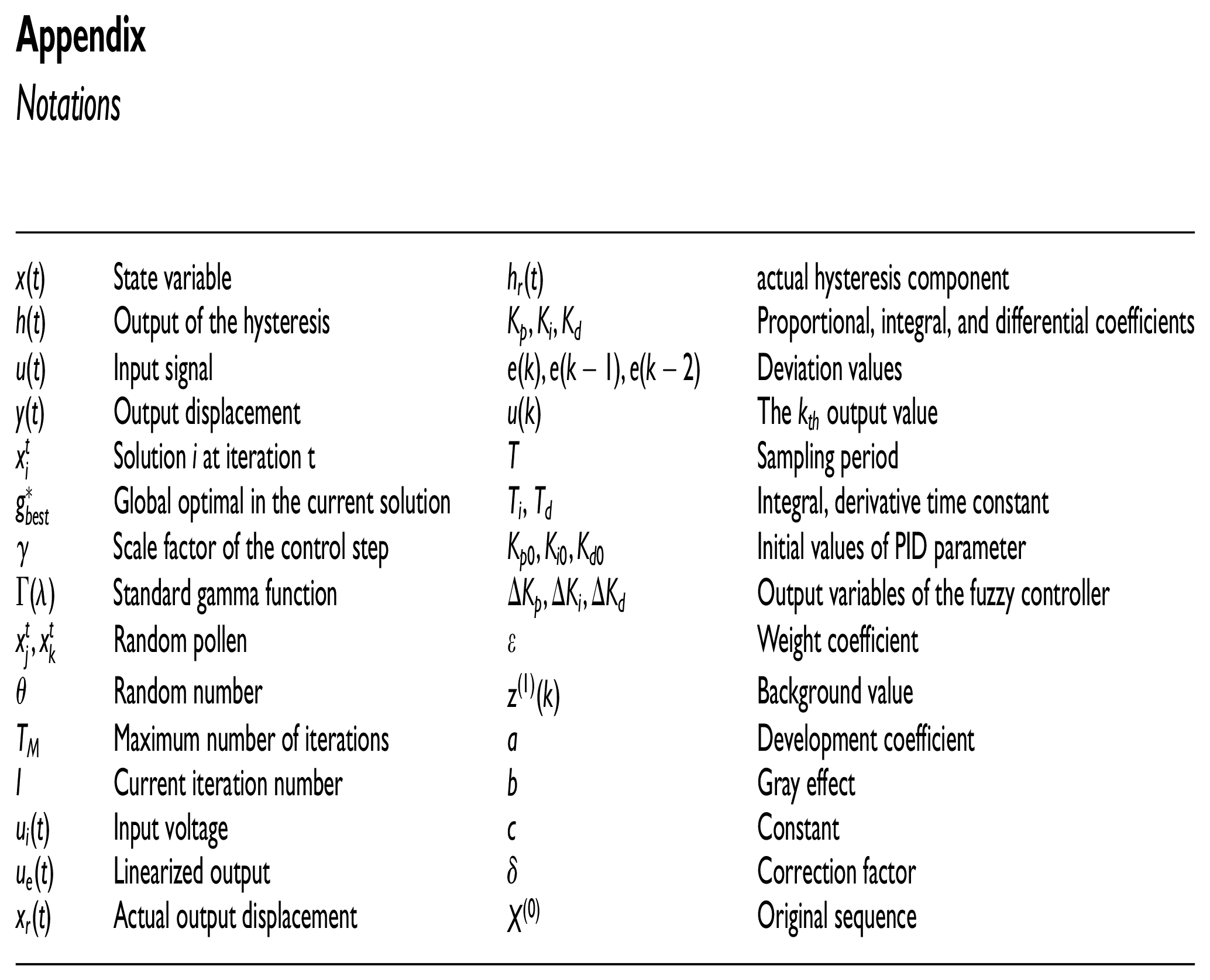
| State variable | actual hysteresis component | ||
| Output of the hysteresis | Proportional, integral, and differential coefficients | ||
| Input signal | Deviation values | ||
| Output displacement | The output value | ||
| Solution i at iteration t | Sampling period | ||
| Global optimal in the current solution | , | Integral, derivative time constant | |
| Scale factor of the control step | Initial values of PID parameter | ||
| Standard gamma function | Output variables of the fuzzy controller | ||
| Random pollen | Weight coefficient | ||
| Random number | Background value | ||
| Maximum number of iterations | Development coefficient | ||
| Current iteration number | Gray effect | ||
| Input voltage | Constant | ||
| Linearized output | Correction factor | ||
| Actual output displacement | Original sequence |
Author contributions
ML: Writing-original, draft preparation; XF: Conceptualization; JL: Conceptualization, supervision; JZ: Investigation, validation; YD: Data curation, formal analysis; ZH: Data curation, formal analysis. All authors have read and agreed to the published version of the manuscript.
Declaration of Conflicting Interests
The author(s) declared no potential conflicts of interest with respect to the research, authorship, and/or publication of this article.
Funding
The author(s) disclosed receipt of the following financial support for the research, authorship, and/or publication of this article: This research was funded by the Natural Science Foundation of Jilin Province (YDZJ202201ZYTS534), Science and Technology Bureau Key Research and Development Projects of Changchun (21ZGG08), Micro-Nano and Ultra-Precision Key Laboratory of Jilin Province (20140622008JC).