
Abstract
Herein, the microwave transmission method is proposed that demonstrates such advantages as non-invasiveness, excellent penetration performance, and fast detection. As a key component of the microwave method water content measurement instrument, the antenna is required to have a smaller radiation size than the inner diameter of the oil pipe. To address this technical challenge, a small-sized microwave projection method based on water content measurement antenna is designed in this study for the water content measurement of oil-water mixtures in downhole pipelines. Also, the half-cut antenna with a size of
Keywords
Introduction
Due to the long-standing routine of using the water injection-based extraction method, most oil fields in China have entered the stage of high water content development. 1 With the increase of water content in the output fluid of oil wells, the significant parameter of water content is proposed in the process of oil-field extraction, so as to facilitate the measurement. 2 The accurate measurement of this parameter is essential for determining the water output of a well and its location, estimating the production of the oil-water mixture, performing intelligent stratification of oil recovery, and predicting the development life, etc. 3
At present, there are various methods proposed for the measurement of water content at home and abroad. In general, these methods can be divided into four types according to their rationales: density method, conductivity method, ray method, and microwave method. Alternatively, the above measurement methods can be divided into two categories: contact measurement methods and non-contact measurement methods. The density and conductivity methods require physical contact, while the ray and microwave methods do not. 4 Besides, the density method is suitable mainly for measuring the water content of less than 5%. There is a single sampling volume that is small and the sampling period is long. 5 As for the conductivity method, it is easy to scale on the sensor surface during long-term service. 6 RF method is costly and not suitable for large-scale promotion. 7 Microwave measurement method, according to the object to be measured on the microwave radiation or transmission and other characteristics microwave sensor sensitive to non-electricity is applied to convert the non-electrical quantity of the substance to be measured into electrical parameters. 8 The microwave measurement method is advantaged by no requirement for physical contact, the capacity to penetrate non-metal objects, a wide band, high transmission, the resistance to low-frequency interference, and other characteristics. 9 Besides, it enables loss-free, real-time, and rapid measurement online. Comparatively, microwave measurement technology is relatively mature, showing such merits as no contact, no damage, no toxicity, the ease of operation, high safety performance, low cost, etc. To sum up, it has promising prospects for practical application. 10
The microwave measurement method can be divided into the trans-missive method and resonant cavity method. Since the resonant cavity method is commonly used for oil-water mixture with low water content, and the transmission method has a wider measurement range, this paper chooses to use the microwave transmission method for water content measurement. The microwave transmissive method is based on the different absorption rates of microwave signals by oil-water mixture with different dielectric constants for water content measurement.
11
According to the characteristics of the electromagnetic wave transmission, the microwave sensor plays the most important part in the measurement system. Besides, as for the accuracy and range of the water content measurement of the oil-water mixture, they are determined largely by the performance of the sensor.
9
Given the confined downhole space of oil wells and the small inner diameter of pipes, it is essential to minimize the size of oil-water mixture water content measurement instruments, especially microwave sensors. The sensor proposed for water content measurement by 12 is a microwave spiral antenna, the size of which is designed to be
Herein, a miniaturized antenna is designed as a microwave sensor that takes into account the process of antenna installation for the downhole water content meter and other measurement devices to occupy the center channel of the pipe. According to literature,13–16 the maximum inner diameter of the pipe is 150 mm. This paper is aimed to design a miniaturized antenna according to the above pipe size. Since the designed antenna has a size that is much smaller than the inner diameter of the pipe, the optimized antenna is characterized by the simplicity of structure, wide band, and compactness, thus meeting the experimental requirements.
Principle of water content measurement by microwave transmission method
Relationship between dielectric constant and water content
In general, the mixed media consist of a mixture of substances that vary in dielectric constants, which is one of the most significant parameters required for measuring the water content of oil-water mixture. Wiener 13 put forward an empirical formula for the dielectric constant of two-component mixed media14,16:
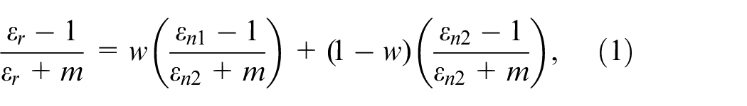
where
When pure water is one of the substances in the mixed medium, the constant denoted as

where
The relationship between oil-water absorption of microwave and water content
As polar molecules, water molecules tend to be polarized into dipoles when electric field force is exerted. With the increase in frequency of the external electric field, the dipole will keep changing direction with the change in direction of the electric field. Besides, collisions will occur during the change of direction, which diminishes electric field energy.
17
Usually, the complex permittivity denoted as

where

From equations (3) and (4), equation (5) is deduced as:

According to equations (2)–(5), both the relative permittivity of oil-water mixed media and the relative loss angle tangent are related to the water content. Also, the relative loss angle tangent can be expressed as equation (6).

where
Relationship between relevant parameters of the oil-water mixture and the water content.
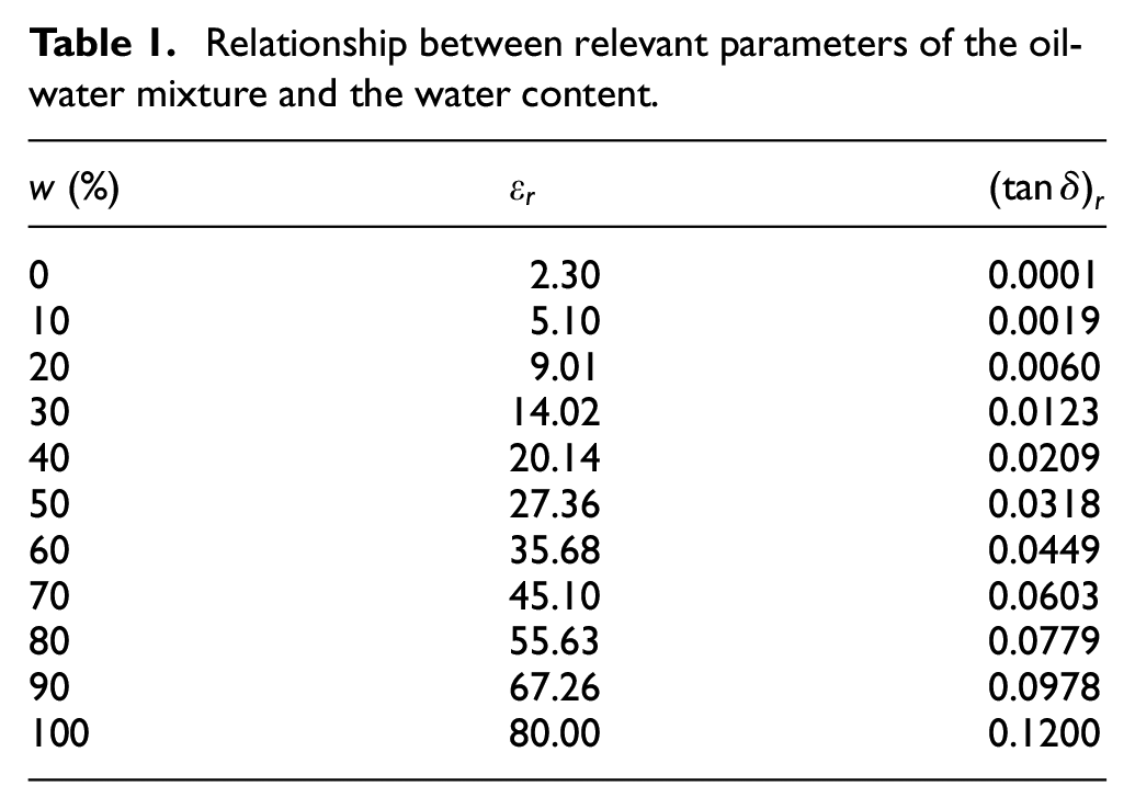
According to Table 1, at room temperature and under normal pressure, the water content of the oil-water mixture varies between 0 and 100%. Meanwhile, the relative permittivity shows an upward trend, varying between 0 and 80. With the continuous increase in the water content of the oil-water mixture, the loss tangent angle increases as well, varying between 0 and 0.12. According to study of 15 and that of 18, the complex permittivity of general materials is
Microwave transmission method of moisture content measurement principle
The principle followed to perform measurement under the microwave transmission method is based on the loss of energy caused when the microwave signal passes through the measured object to detect the water content of the measured material. 15 Figure 1 shows the microwave transmission method as adopted when a uniform plane wave approaches the measured medium in a vertical incidence.
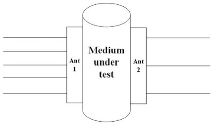
Schematic diagram of microwave measurement.
As shown in Figure 1, when the microwave passes through the measured medium, the change to the dielectric constant of the measured medium will lead to the attenuation of the microwave signal. When the oil-water mixture is filled with the medium under test, the electromagnetic wave complex propagation constant falls within the range of 10 and 11:

where

When

Thus, the attenuation of the microwave signal


where
Antenna design of microwave transmission method water content measurement instrument
The microwave sensor is applied to deal with electromagnetic wave transmission and reception. Besides, the performance of the antenna has an immediate impact on the accuracy of the test. 18 Herein, by taking into account the requirement of miniaturization, the analysis of various antennas is conducted, with the half-cut antenna selected as the detection sensor for water content under the microwave transmission method.
Microwave transmission method of water content measurement principle
The full-wave 3D electromagnetic simulator CST Studio suite is adopted to design and optimize the half-cut antenna proposed in this study. By optimizing the characteristics of impedance, reflection coefficient, antenna gain, and other parameters of the antenna, the performance of the antenna can be improved. Considering a variety of influencing factors and the requirements on the performance of the designed antenna, the material used to build the dielectric layer of the antenna is determined as FR-4 (epoxy board with high mechanical properties and dielectric properties), and the dielectric constant of the dielectric layer is 4.3. The basic radiating patch antenna of the antenna design is shown in Figure 2(a), the designed half-cut antenna is illustrated in Figure 2(b), the physical diagram of the designed antenna is illustrated in Figure 3, and the related characteristics are shown in Figure 4. The selected reference antenna is a microstrip antenna with a
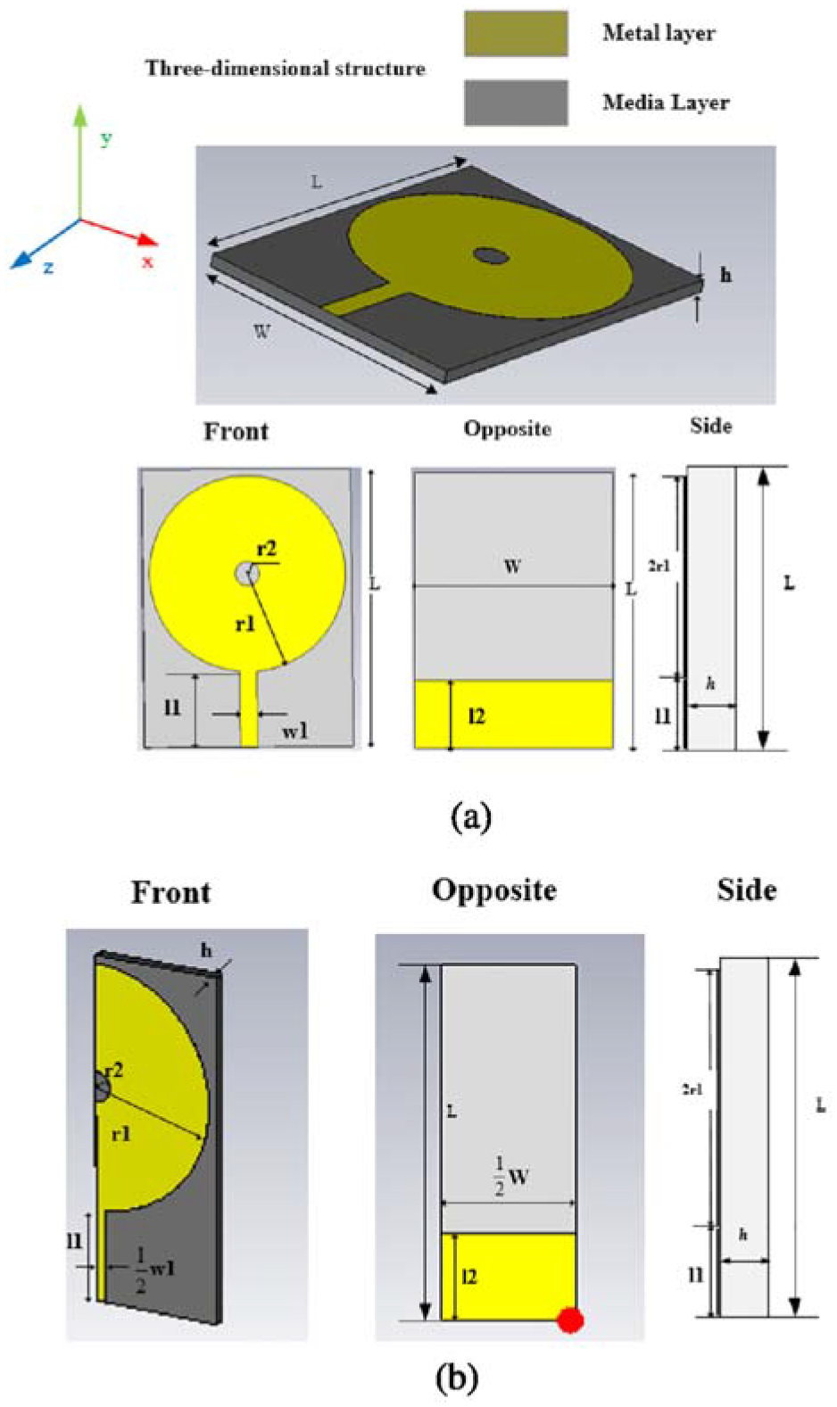
Evolution of the proposed Antenna: (a) detailed structure diagram of the antenna and (b) half-section antenna treated by dichotomy.
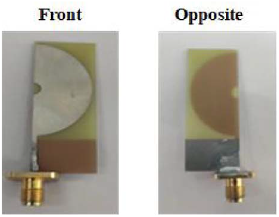
Physical view of the antenna.
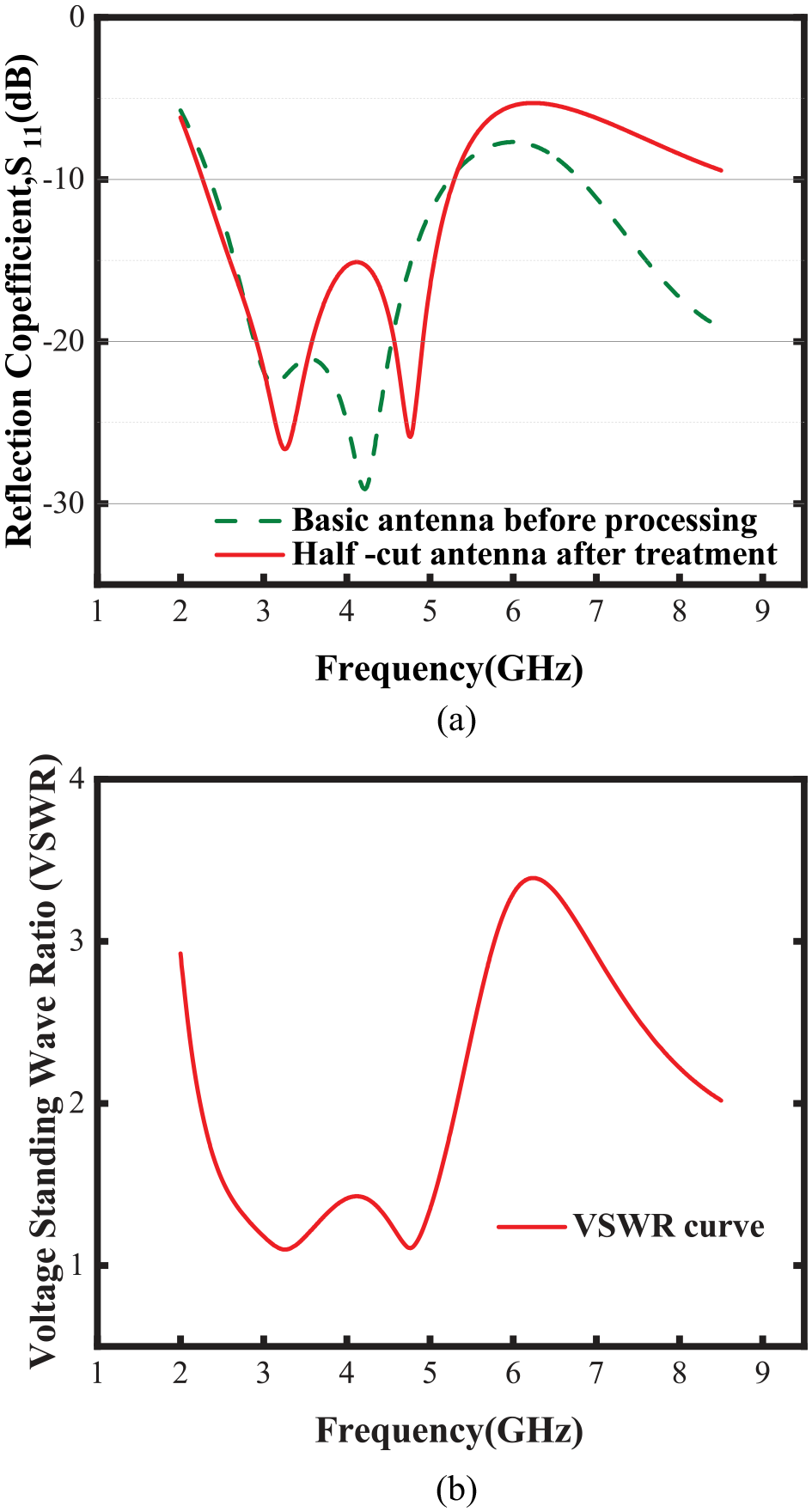
Correlation characteristic curve of antenna: (a) the
Structural dimensions of the antenna.
where L, W, and h represent the length, width and thickness of the dielectric layer of the antenna, respectively. r1, r2, w1, l1 represent the outer diameter, inner diameter, length, width of the metal layer of the antenna, respectively. l2 represents the length of the metal layer of the opposite antenna.
The basic antenna size is sized
As shown in Figure 4(a), the bandwidth of the basic antenna before the dichotomy is 3.04 GHz, and the bandwidth of the half-cut antenna after processing is 3.06 GHz. Compared with the basic antenna, the bandwidth is basically unchanged. And from the observation of the transmission coefficient
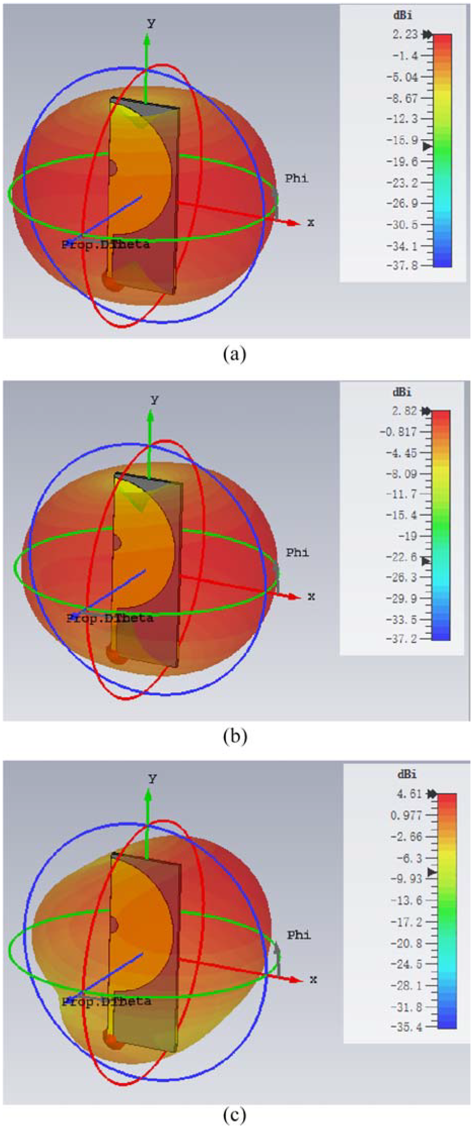
Far-field setup: (a) radiation direction diagram of 2.45 GHz, (b) radiation direction diagram of 3.25 GHz and (c) radiation direction diagram of 4.77 GHz.
As shown in Figure 5, the antenna is an omnidirectional antenna, and the gain of this antenna is 2.61 dBi in the far-field region of 3.25 GHz, the gain in the far field area of 4.77 GHz is 4.27 dBi. Since the frequency places requirements on the equipment, and the lower the frequency, the larger the antenna size. Considering the size and gain of the antenna, the selected frequency is about 3.25 GHz. Simulation of the test results to take into account the actual measurement effect, the following through the actual measurement to find the highest measurement accuracy between 2.25 and 3.25 GHz frequency point. The measurement results show that the measurement linearity is better at 2.45 GHz. As shown in Figure 4(b), the voltage VSWR is less than 2 at 2.45 GHz, and the known standard of VSWR, VSWR<2. It is known that the designed antenna bandwidth meets the experimental requirements.
Antenna characterization
For the design of the antenna, an analysis is conducted as to the impact caused by the thickness of the dielectric plate and the width of the microstrip line on the performance of the antenna. Besides, the design of the miniaturized antenna can be worked out easily by analyzing the performance of the parameters. Figure 6 shows the relationship between the thickness of the dielectric plate h and the width of the ground plate w1 and the ultra-wideband performance when other parameters are unchanged.
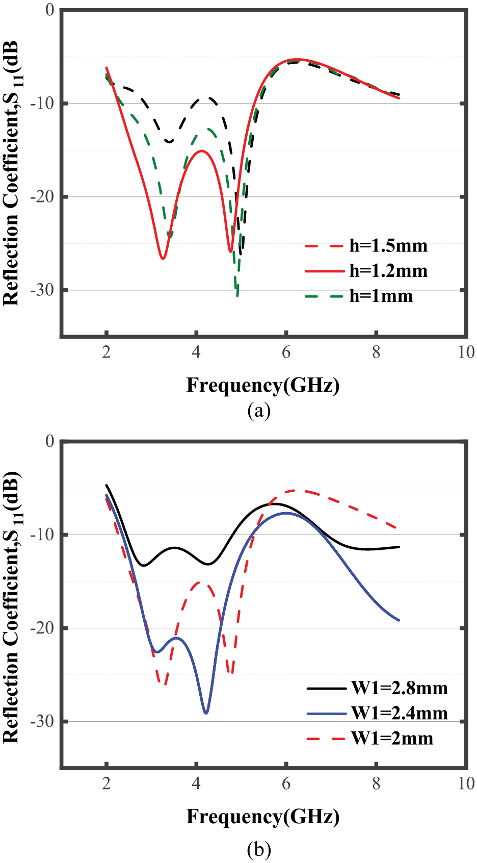
The effect of two parameters on the reflection coefficient
As shown in Figure 6, when the thickness is 1.5 mm, the antenna bandwidth range of
Antenna performance test of microwave transmission method water content meter
Construction of an experimental environment
Figure 7 illustrates the water content test model of the oil-water mixture. The oil-water mixture exists in a metal pipe with a height of 110 mm, an inner diameter of 50.30 mm, and a wall thickness of 1 mm. In order to make the electromagnetic waves emitted by the antenna penetrate the metal pipe, holes are drilled on both sides of it and then filled with the materials resistant to high temperature and pressure. This ensures the wave transmission expected. Then, the designed transmitting and receiving antennas are installed on both sides of the metal pipe. The antenna used in the experiment is a half-section antenna. The
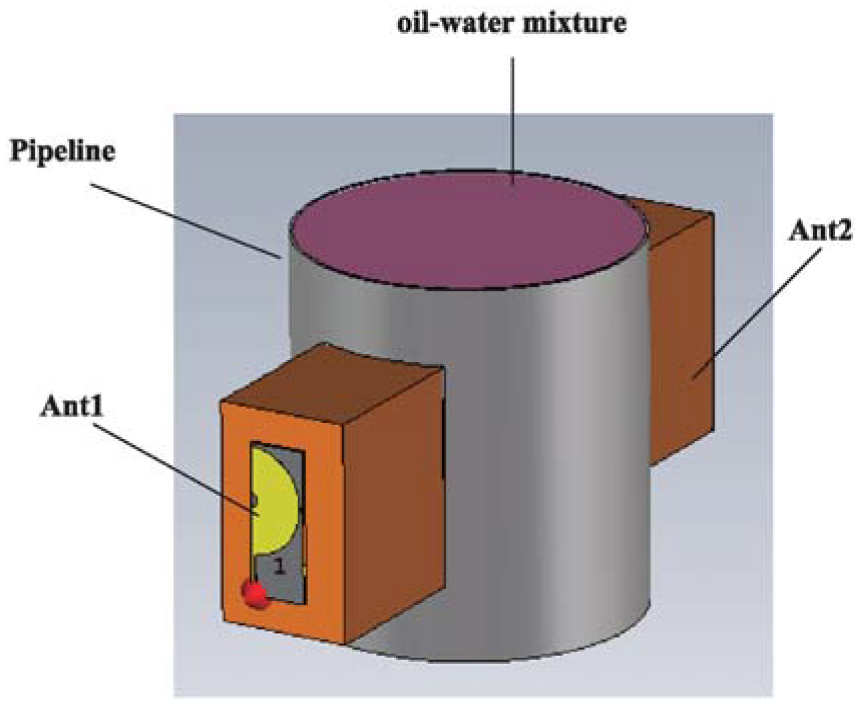
Water content model of oil-water.
Simulation analysis of the effect of antenna transmission coefficient on water content
For the CST solution, the antenna operating band is set to 2–6 GHz, the half-cut antenna on the left is set as the transmitting antenna, and the half-cut antenna on the right is treated as the receiving antenna. This is to study the change of transmission coefficient
Experiments were conducted to measure the water content of the oil-water mixture from 0% to 100%, with the interval of measurement set to 10% for each test. For this reason, the experimental test was conducted on diesel. The results of experimental measurements are shown in Figure 8. When water content is in the range of
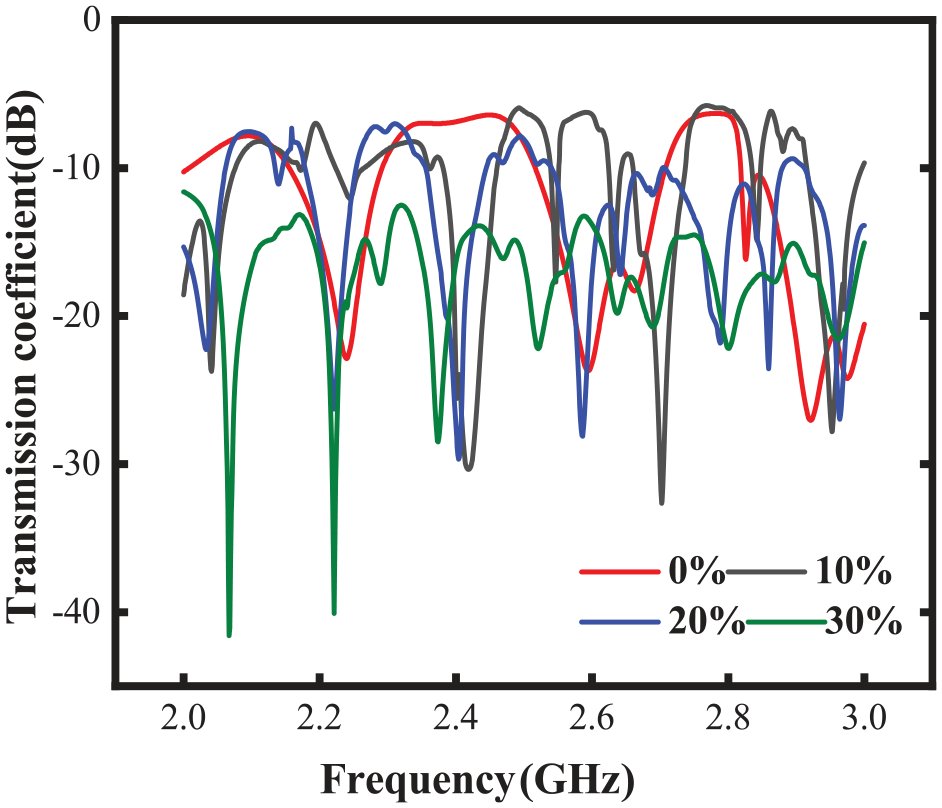
Antenna transmission coefficient curve when the water content varies from 0% to 30%.
Figure 9 shows the curve of changes in the transmission coefficient
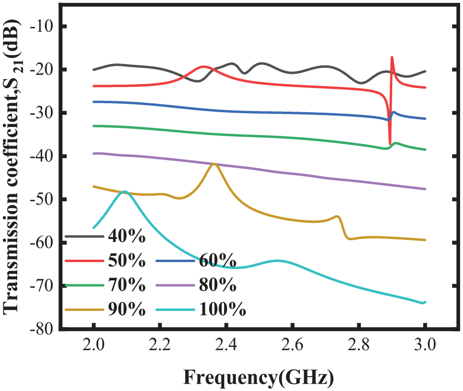
Antenna transmission coefficient curve when the moisture content varies from 40% to 100%.
Figure 10 shows the simulation results of water content from 0% to 100%, with the frequency set to 2.45 GHz for the system. To further elaborate on the relationship between transmission coefficient

where
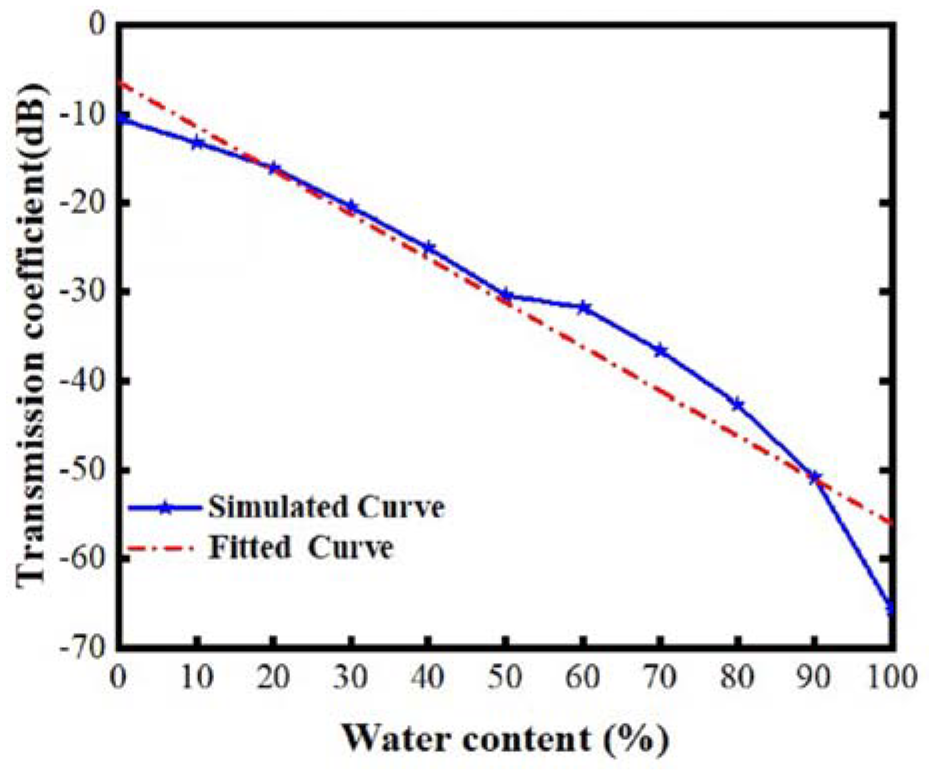
Water content simulated curve from 0% to 100%.
As shown in Figure 10, the fitting degree of the trend line
Measured analysis of the effect of antenna transmission coefficient on water content
The
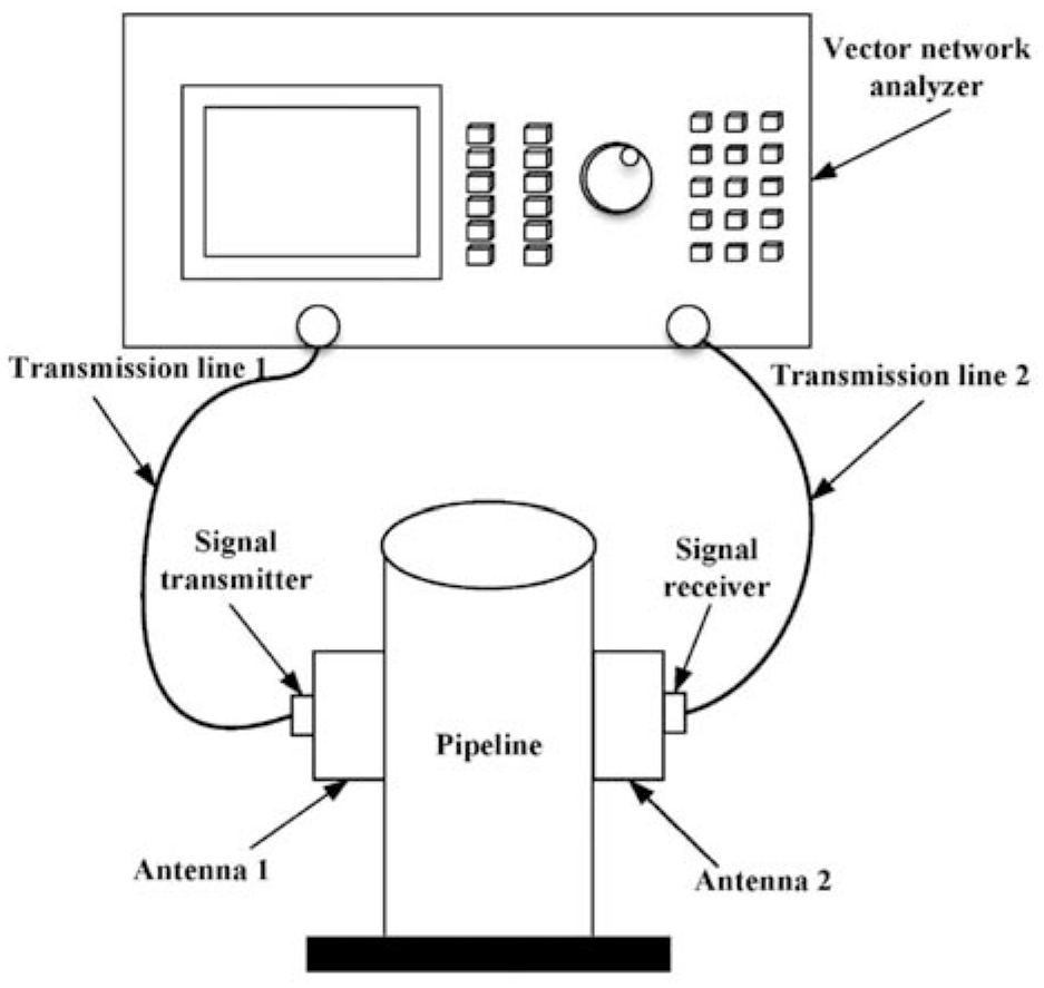
Block diagram of microwave transmittance water content meter.
When the vector network analyzer is used to measure the water content of crude oil in the system, the experimental system is developed according to the measurement principle as shown in Figure 11. The data of transmission coefficient were tested by the vector network analyzer at a water content ranging from 0% to 100%, and an analysis is conducted on the relationship between water content and transmission coefficient. That is to say, the transmission coefficient varies with a continuous increase in the water content of crude oil. Figure 12 illustrates, a vector network experimental test on the microwave crude oil with a water content of 80%.
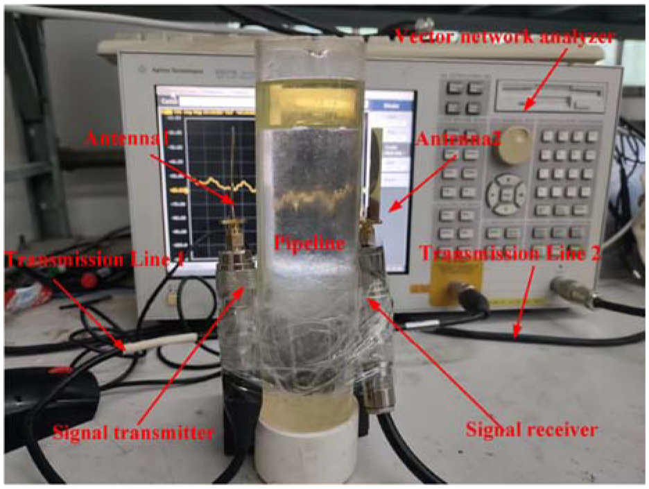
Experimental setup in actual measurement.
The measured medium is placed in a glass container with a diameter of 50.30 mm. Then, the variation in the transmission coefficient
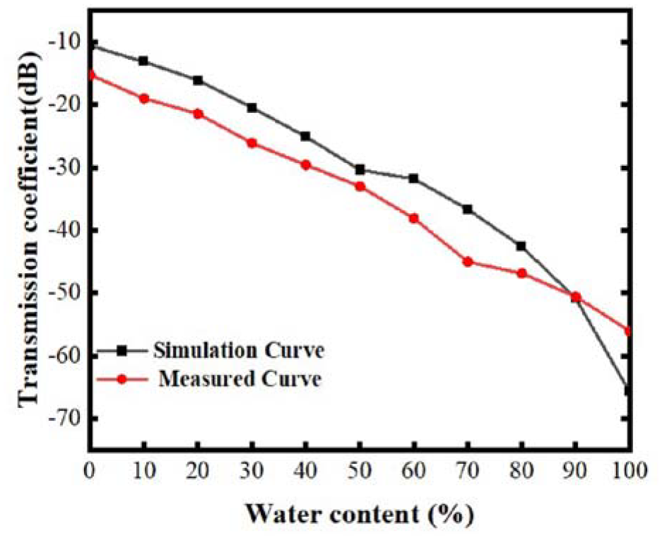
Simulated and measured comparison of water content from 0% to 100%.
Simulation results and relative error of transmission coefficient
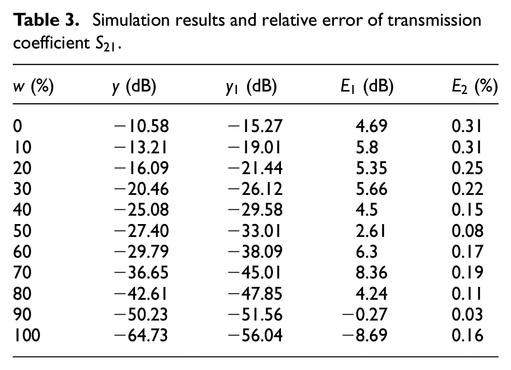
In the microwave transmission method water content testing system, in order to verify whether the loss error of the oil-water mixture within the range of
where
Based on the comparison of transmission coefficient
(1) When the percentage of water content in crude oil is lower than 30%, the absolute error difference between the analog measurement and the loss measured by vector network analyzer is small; When the water content of crude oil is higher than 30%, there is a small difference between the loss measured by analog measurement and that measured by vector network analyzer. The main reason is that when the water content of crude oil is higher than 30%, it can be seen from equations (1) and (2) that the dielectric constant of water begins to play a dominant role in the measurement of the dielectric constant of oil-water mixtures. According to equation (8), the loss on antenna 2 is directly proportional to the dielectric constant of oil-water mixtures. In addition, as the water content of crude oil increases, the oil-water mixture changes from a weakly conductive medium to a strongly conductive medium. Therefore, when the water content of crude oil exceeds 30%, Due to the insensitivity of the antenna in a high water content state, the absolute error between the percentage of water content between the two will gradually increase.
(2) If the transmission coefficient
We added a comparison of the proposed scheme with the state of the art in the literature, as shown in Table 4. And the corresponding textual description of Table 4 is provided.
Performance comparison with the state of the art in literature.
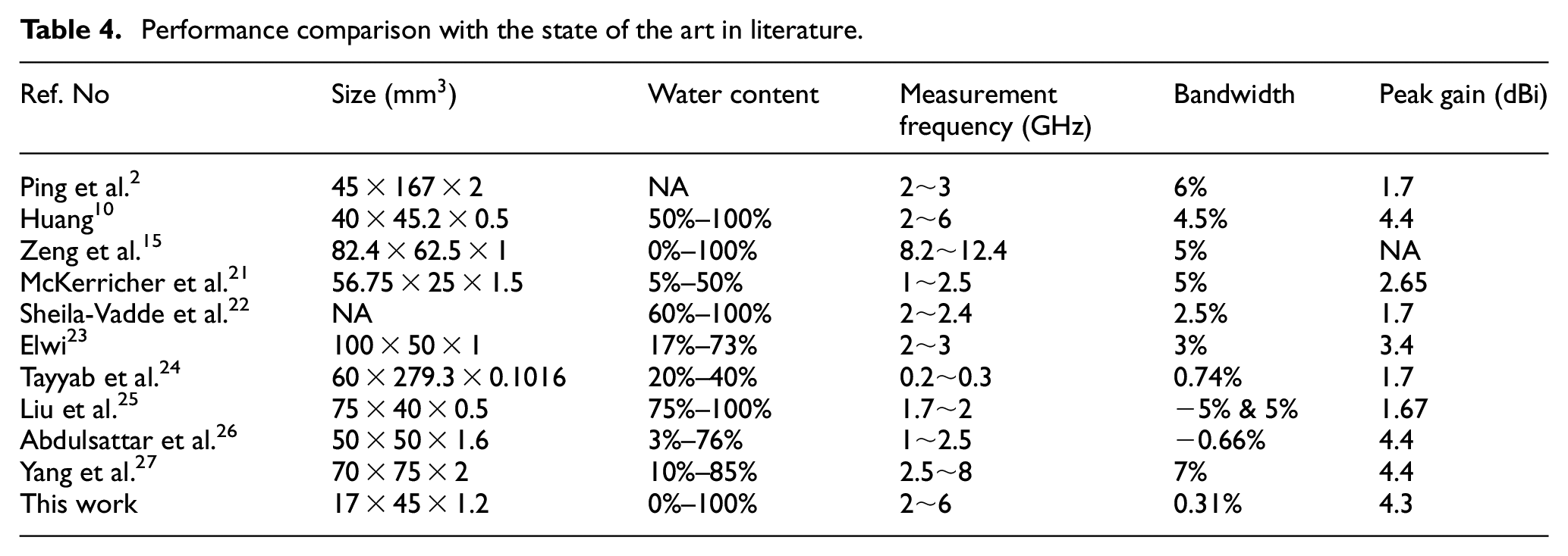
Table 4 compares the performance and characteristics of the proposed water content with the most advanced water content-related performance reported in the literature. Some important features proposed are as follows:
(a) The proposed antenna was developed on a microwave laminate with a thickness of 1 mm. As is well known, the bandwidth of the antenna decreases as the thickness of the microwave laminate decreases. However, in the proposed technology, a broadband bandwidth of 3.04 GHz was achieved. This makes the antenna suitable for measuring microwave water content in the 2.25–5.29 GHz spectrum. Therefore, the implementation bandwidth of the proposed miniaturized antenna is greater than the bandwidth reported in refs.2,10,21–26
(b) Unlike the research reported in refs.,2,15,21,22 the proposed miniaturized antenna is implemented on microstrip patch antennas to achieve ultra-wideband high gain antennas.
(c) The research in refs.2,25 focuses on developing spiral antennas with high-precision water content. However, antennas are suitable for narrow ranges and are not suitable for experimental measurements across the entire range.
(d) Different from refs.,21–24,26,27 the proposed antenna is essentially broadband and does not use complex electromagnetic structures such as metamaterial to achieve miniaturization.
(e) The measurement of crude oil water content is conducted at lower frequencies, which is one of the limiting factors for achieving antenna miniaturization. Unlike the work reported in refs.,10,21,26 the antenna for water content measurement tends to be miniaturized and has relatively low frequencies.
(f) Although the minimum operating frequency of the antenna reported in refs.21–23,25 is lower than 2.45 GHz, the relative error of the antenna’s water content is relatively high, higher than the relative error of 3% water content.
(g) Although the reported water content error in refs.24,26 is comparable to the proposed error, the applicable range of water content for antennas is narrow and the size is large. On the other hand, the dielectric constant of the antenna reported in Abdulsattar et al. 26 is 4.4.
(h) Although the antenna size reported in Abdulsattar et al. 26 is physically equivalent, the antenna is limited by antenna frequency and relative dielectric constant.
(i) Although the antenna bandwidth reported in refs.15,27 is greater than 4 GHz, the antenna is limited by antenna size and frequency size.
(j) Although the physical size of 10 is comparable to the proposed slot antenna, the proposed antenna is electrically smaller due to its minimum operating frequency of 3.8 GHz.
Conclusion
This paper proposed a new type of circular slot antenna with a 50% size reduction. The size reduction is realized by exploiting the structural symmetry along the principal planes of the antenna. The reference circular slot antenna reduces its size while achieving broadband impedance and radiation characteristics. Studied the impact of miniaturization on bandwidth and radiation characteristics, and provided results. The proposed miniaturized antenna covers wide bandwidth with broadband ranging from 2.25 to 5.29 GHz and gain ranging from 2.61 to 4.27 dBi. The radiation pattern is omnidirectional making the antenna suitable for broadband applications. By analyzing the relationship between the water content and the transmission coefficient
Footnotes
Declaration of conflicting interests
The author(s) declared no potential conflicts of interest with respect to the research, authorship, and/or publication of this article.
Funding
The author(s) disclosed receipt of the following financial support for the research, authorship, and/or publication of this article: This work was supported in part by the Xi’an Science Foundation, Shaanxi Province, China, Grant No. 21XJZZ0058, and by the Postgraduate Innovation and Practice Training Program of Xi’an Shiyou university, No.YCS21213209.