
Abstract
Multi-microgrids offer various benefits including the decreased overloading of a single microgrid, more options during faulty conditions, and more utilization of renewable energy resources. However, the implementation of a multi-microgrid brings the challenges such as power system complexity, interconnection issues, bidirectional power flow management, and power flow balancing. In the presence of these challenges, the power flow stability of the multi-microgrids is a challenging problem. In this context, this study evaluates a transient stability analysis model in multi-microgrids using solar photovoltaics, wind power, and a unified power flow controller (UPFC). UPFC offers a more robust power flow control strategy compared with other flexible alternating current transmission systems (FACTS) devices. First, a multi-microgrid structure consisting of the two microgrids was designed in DIgSILENT PowerFactory software. Second, the load flow calculation was performed in the absence and presence of UPFC, short circuit fault, and grid connection. Third, the electromagnetic transients (EMT) simulation was performed for all these situations. The results exhibited that the UPFC would offer significant power flow stability in the multi-microgrids. It was observed that the UPFC resulted in more transient stability in the microgrid where it was located. However, it improved the power flow quality at all the locations in the multi-microgrids. In addition, UPFC offered significant transient stability during the fault occurrence. The results offer various insights into power flow management in multi-microgrids.
Keywords
Introduction
There is an increased trend in the world toward the extensive integration of renewable energy resources (RERs) into power systems due to the depletion of fossil fuels and the protection of the natural environment. 1 However, the progress is very slow due to the issues such as the high cost, planning issues, and fluctuating nature of the major RERs. 2 The integration of the RERs into the power systems is a challenging issue. The microgrids are increasing the integration of RERs resources into the power systems. 3 Microgrids offer various benefits such as more utilization of renewable energy resources (RERs), a decrease in the overloading of the main grid, an increase in electricity access to remote areas, and more availability of electricity. Still, the progress is slow due to the small-scale nature of the microgrids. The integration of two or more microgrids is a good idea to increase the utilization of RERs.4,5 The integration of two or more microgrids is called a multi-microgrid (MMG) or microgrid cluster. Recently, MMGs are gaining more attention due to their advantages compared with single microgrids.
Multi-microgrids (MMGs) offer various advantages to power systems. These advantages include more reliability, sustainability, low cost, and flexibility.6–11 In addition, the MMGs would decrease harmonic issues, decrease voltage fluctuations, and increase protection. 12 Also, the connection of multiple microgrids would significantly reduce the overloading on the national grid. 13 In this way, the dependence on the national grid decreases.14–16 In many parts of the world, many places have a large amount of renewable energy potential. In such places, the single microgrid may face capacity constraints. It is not feasible to integrate a large number of RERs into a single grid. The connection between multiple microgrids would help in the improvement of the overall power system. 17 In this case, MMGs would facilitate the integration of large amounts of RERs. 18 There are a large number of villages in the world without electricity and with substantial RERs, which would trigger the development of MMGs. 19 For instance, India has 18,000 rural areas with the least possibility of a national grid connection. 20 In such cases, the MMGs would help in the electricity demand fulfillment of in these regions. In the presence of disruptions in the utility grid, a single microgrid may not maintain stability in the power supply to critical loads. In such situations, the MMGs may stabilize the power system. 21 Moreover, multi-microgrids offer large-scale electricity generation leading to a large amount of sustainable electricity generation. 22 In the present times, there is a tendency toward the development of a large number of grid-connected and islanded microgrids. In parallel, there is a tendency for the proximate microgrids to connect with each other. These tendencies would result in the development of novel methods for the operation and connection of MMGs.23–26 The MMGs allow the sharing of generation, transmission, and economic resources between different regions with different capabilities, which would save the investments on common resources.27,28 The coordinated operation of microgrids can reduce total investment and operation costs and would significantly enhance the reliability of the whole distribution system. In contrast to the above advantages, MMGs bring several disadvantages that should be addressed before their integration into the power systems. Hence, extensive research is required to address the potential disadvantages of the implementation of MMGs.
MMGs add complexity to the power systems due to the integration of a more number of RERs and the power flow balancing between microgrids.29,30 Another challenging issue in MMGs is the two-way power flow between different grids. 31 In addition, MMGs involve more power flow fluctuations at the transmission and distribution stages. 32 Moreover, power flow control is challenging in the MMGs due to the more uncertainties in the system. 33 Hence, proper power flow analysis is required for the successful operation of the MMGs. In this context, the focus of this paper is to perform the power flow analysis in MMG.
In the existing literature, several papers have performed the power system analysis in the microgrid cluster using different techniques. For instance, one research study used a unified interphase power controller (UIPC) for the power flow control between interconnected microgrids in hybrid microgrids. 34 It was concluded that the performance of UIPC was better that the conventional interlink converters (ILCs). In that paper, a hybrid AC/DC microgrid was studied in the presence of IPFC and the effectiveness of UPFC was not evaluated. However, the present paper includes two AC microgrids using UPFC. The present study does not include a DC microgrid but it utilizes UPFC in the multi-microgrid. Another study designed an interlinking converter for multiple AC/DC microgrids in Simulink software. 35 In that study, the MMGs were interlinked using a voltage source inverter with a droop controller. The simulation exhibited a successful power flow, good voltage stability, and good frequency stability. Rahman et al. 35 used the interlinking converter in the analysis of the AC/DC hybrid microgrid but the present paper used UPFC in the two AC microgrids. Hence, the UPFC has not been used in the research reported in Rahman et al. 35 A third study designed a DC/AC multiple microgrids using a decentralized controller which exhibited the simultaneous power control capability for individual and multiple microgrids. 36 However, that paper did not focus on the multiple AC microgrids. In addition, the present paper evaluated the performance of UPFC in the presence of a short circuit. A fourth research study designed a power flow controller based on the bridge converters for DC multiple microgrids. The results exhibited that the proposed concept is a good option for the connection between DC microgrids. 37 However, that research was based on the DC microgrids. In contrast, the present paper reports the AC microgrids using UPFC. A fifth study designed the frequency and voltage controllers for the MMGs using distributed cooperative control. The proposed controllers exhibited good stability under various changes in the power system. However, that work does not consider UPFC and transient stability analysis. 38 A sixth study designed an energy router for AC-DC multi-microgrid based on the common DC link between the microgrids using Simulink. 39 Again, that research analyzed the hybrid AC-DC microgrids using DC-link-based energy routers interface. In this regard, UPFC could improve the AC-DC microgrid through its placement at the appropriate location. However, the present paper utilizes UPFC for the comprehensive transient stability analysis of AC microgrids. A seventh study investigated a wind-solar-based MMG with battery storage based on the voltage source converter. 40 This study used a voltage source converter which is the base of the UPFC. In fact, UPFC utilizes the coordination between two voltage source converters and could perform better than a single voltage source converter. Hence, the present study addressed this issue through a comprehensive analysis. Also, that work used a PV system in one microgrid and a wind power system in another microgrid. In contrast, the present paper used PV systems and wind power generation in both multi-microgrids. An eighth study investigated the behavior of DC MMG using the distributed control method. In this reference, the minimum cost and voltage regulation were achieved in the presence of fault. 41 Again, that paper was only based on the DC multi-microgrids. A ninth research study performed power flow analysis in a multi-microgrid using ETAP software considering the effect of grid connections and renewable energy integration. In addition, that research investigated the carrying capacities, carried currents, percentage occupancy, power losses, and voltage drop rates of all lines. 42 A 10th study presented a multiple-objective optimization model with three objectives including feeder congestion, voltage variability, and cost. In that research, the two microgrids were linked using a distribution-interline power flow controller (IPFC). This controller used two voltage source converters linked through a direct current (DC) link. 43 The present work used UPFC which connects and works differently as compared to IPFC. Similarly, an 11th study presented multiple objective optimization models with three objectives including energy loss, voltage variability, and cost. 44 In that reference, two microgrids were linked using a distribution-interline power flow controller (IPFC). A 12th research study performed the power quality analysis for microgrids using electromagnetic transients (EMT) simulation in a PowerFactory environment. 45 There are some other studies on multi-microgrid analysis.46–48 Table 1 presents a contribution of this paper in a compact way with respect to the existing literature.
Existing literature on the power flow analysis of multi-microgrids.
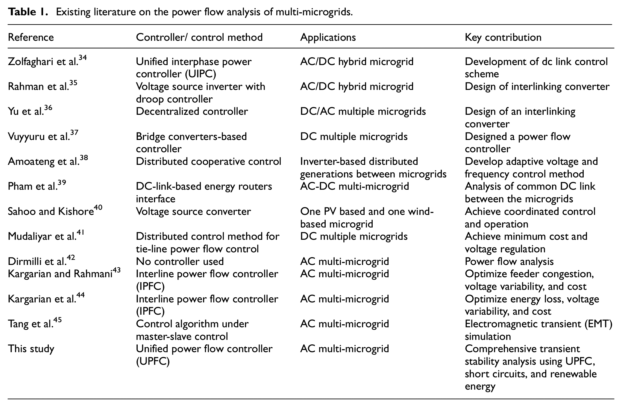
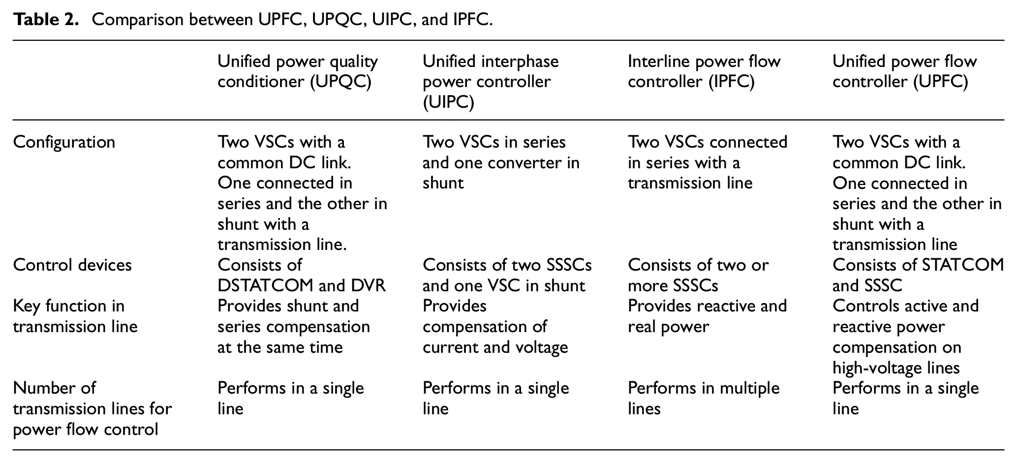
In the existing literature, most of the above studies focused on the topics such as energy management, scheduling, optimization, and cost estimations. In the existing literature, the power flow analysis is the least researched area, which is a fundamental necessity for emerging power systems including MMGs.49,50 Specifically, the integration of flexible alternating current transmission systems (FACTS) devices into MMGs would be a promising step toward power flow stability. In this regard, some papers performed the power flow analysis of multi-microgrids in different ways using the FACTS devices including UPFC, unified power quality conditioner (UPQC), unified interphase power controller (UIPC), and interline power flow controller (IPFC).51,52 A comprehensive comparison amongst the UPFC, UPQC, UIPC, and IPFC has been presented in Table 2. This comparison is based on the existing literature.53–57 This study has investigated the performance of UPFC in the transient stability analysis because it is more prominent among the other FACTS devices. For instance, one study has reported more power flow stability for UPFC compared with IPFC. 58 In that study, UPFC offered optimum active and reactive power values at significantly fewer capacitor ratings than IPFC. The more capacitor ratings mean the more cost of equipment. Hence, the UPFC offered a better alternative with respect to capacitor value. The various FACTS devices and other controllers may offer a better result. However, the focus of the present paper is to evaluate the performance of UPFC for the power flow analysis of MMGs. This paper configured the UPFC based on the standard pulse-width modulation (PWM)-converters, which is a powerful tool for the analysis of the advanced power system. The effect of UPFC has not been reported for modern multi-microgrids. Hence, the present work configured the UPFC parameters according to the renewable energy based multi-microgrid. In summary, this paper evaluates the transient stability analysis of MMGs using UPFC and renewable energy in the presence and absence of UPFC and grid connection.
Comparison between UPFC, UPQC, UIPC, and IPFC.
The key objective of this paper is the transient stability evaluation in the MMGs using a unified power flow controller (UPFC), wind power systems, and solar photovoltaic (PV) systems. In this regard, the different cases have been evaluated including (a) UPFC not used and short circuit not observed in grid-connected mode, (b) UPFC not used and short circuit observed in grid-connected mode, (c) UPFC used and short circuit observed in grid-connected mode, (d) UPFC not used and short circuit not observed in grid disconnected mode, (e) UPFC not used and short circuit observed in grid disconnected mode, and (f) UPFC used and short circuit observed in grid disconnected mode. This study uses DIgSILENT PowerFactory software for the Modeling and analysis of MMGs. Transient stability of the power system ensures the restoration of the power system under faulty conditions. 59 The presence of a fault would degrade the performance of the power system.60,61 Hence, the impact of the short circuit fault has been included in the evaluation.
The remaining paper has been organized as follows. First, the methodology of the power flow analysis model has been presented. Then, the results and discussion have been presented based on the power system simulation of the proposed multi-microgrid model. Finally, the conclusion of the paper has been presented.
Methodology
This section presents the development of the simulation model in the DIgSILENT PowerFactory and the mathematical model of the proposed system. Figure 1 presents the flowchart of the research methodology.
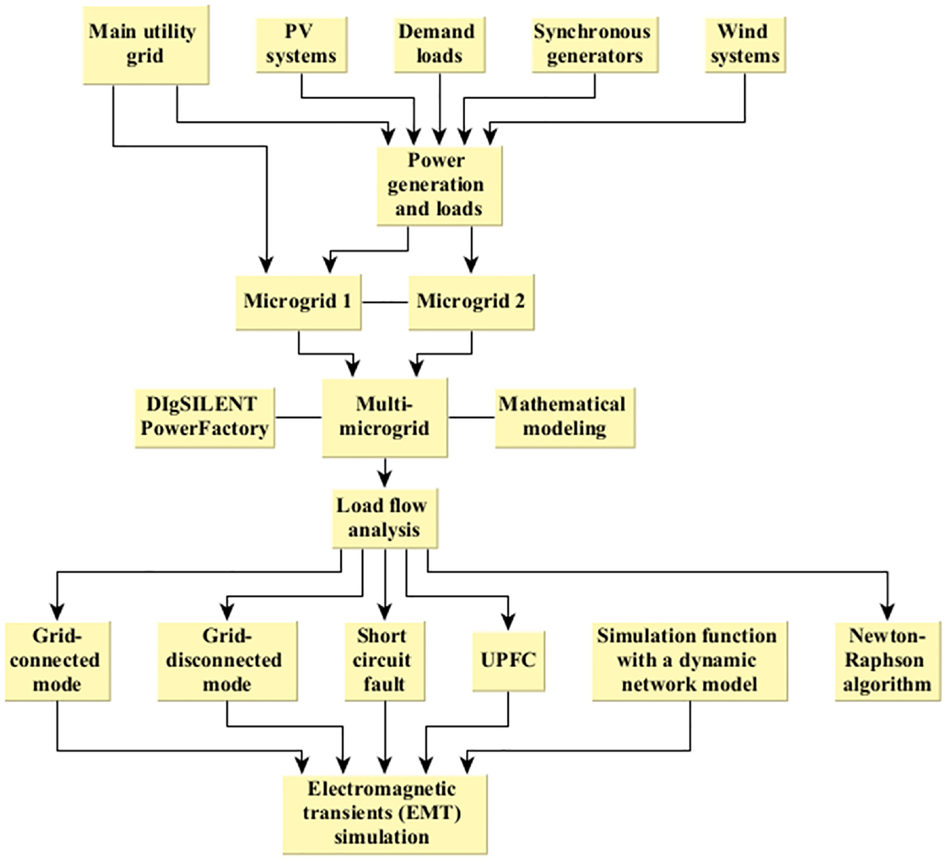
Flow chart of the multi-microgrid modeling and simulation.
Development of simulation model
Figure 2 presents the single-line diagram of the proposed multi-microgrid (MMG). In this system, two microgrids (i.e. MG-1 and MG-2) are interconnected with a 1 km transmission line. Both microgrids contain one PV system, one wind power system, and one synchronous generator. PV system and wind system have been specified with corresponding PQ buses. The synchronous generators in both microgrids have been specified with the corresponding generator bus (i.e. voltage controlled bus). The main utility grid is connected to MG-1 through the corresponding slack bus. Each microgrid requires the satisfaction of 20 MW power demand (i.e. total demand = 20 MW + 20 MW = 40 MW). In both MMGs, the loads are located at a distance of 1 km from the main interconnection busbars.
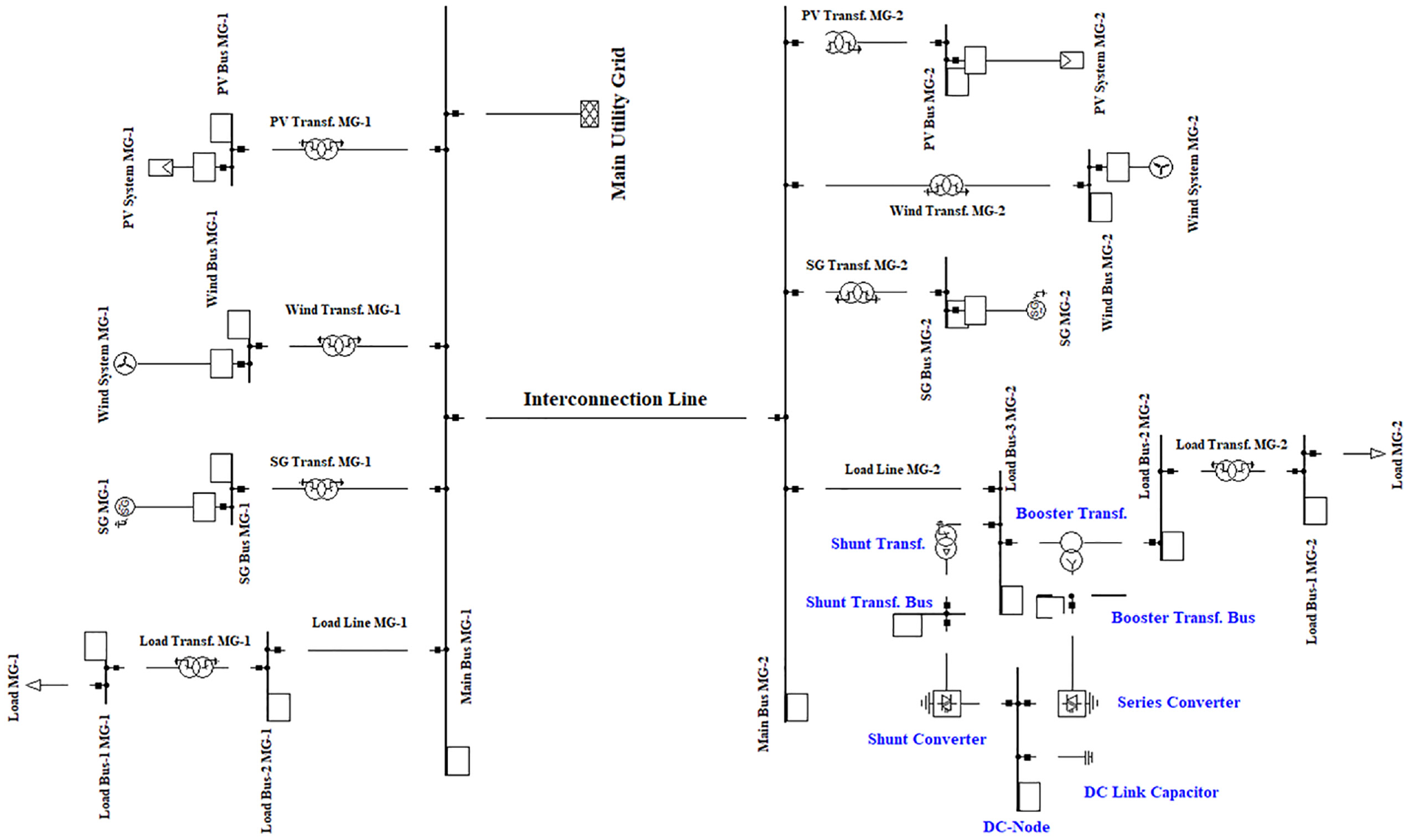
Single-line diagram of proposed multi-microgrid.
The main utility grid is directly connected to the 20 kV system in MG-1. PV system, wind power system, and synchronous generator are connected to the 20 kV system through a step-up transformer (1–20 kV). Each load was step-down from 20 to 1 kV. The parameters for the transformer were set according to the system requirements. In all the generation sources, 3-phase technology was selected in DIgSILENT PowerFactory software. In the PV generation system, 4000 solar panels were used and the active power per panel was 0.0003 MW. Hence, the total capacity of the PV system was 1.2 MW (i.e. 4000 × 0.0003). Similarly, the wind power system used six wind turbines and the active power per turbine was 1.5 MW. Hence, the total capacity of the wind power system was 9 MW (i.e. 6 × 1.50 MW). The active power in each synchronous generator was specified as 12 MW.
The simulation model in Figure 1 was evaluated in the following cases.
UPFC not used and short circuit not observed in the grid-connected mode.
UPFC not used and short circuit observed in the grid-connected mode.
UPFC used and short circuit observed in the grid-connected mode
UPFC not used and short circuit not observed in the grid-disconnected mode
UPFC not used and short circuit observed in the grid-disconnected mode
UPFC used and short circuit observed in the grid-disconnected mode
The short circuit was introduced at both microgrids.
For these cases, the transient stability of the proposed multi-microgrid was analyzed. The electromagnetic transients (EMT) simulation offers an in-depth analysis of the electromagnetic transients in the power system. EMT simulation was preferred due to its ability to provide an accurate and in-depth analysis of transients. It offers a detailed understanding of all the phases and faults. In the presence of faults such as short circuits, EMT simulation offers more reliable results for the development of accurate control methods. In addition, the EMT simulation provides an in-depth analysis in the presence of hundreds of PV panels and wind turbines. In this regard, the detailed EMT simulation provides an accurate basis for the accurate planning, operation, and control of renewable integrated power systems. DIgSILENT PowerFactory offers a highly reliable and accurate way to perform short circuits and EMT simulation simultaneously. The power flow equations were solved by the Newton-Raphson method. The power system equations are the standard equations used by DIgSILENT PowerFactory. The mathematical representation of the proposed MMG has been presented in the following section.
Mathematical modeling
The proposed multi-microgrid model has been developed in PowerFactory software. This software contains various basic elements which can be used to model a wide range of power systems using different control strategies. The various basic elements are based on the standard mathematical models in the field of power system analysis. The technical background related to these elements is available in the technical documentation of this software. In the following, the general mathematical background of the proposed MMG model has been presented based on the technical documentation of the PowerFactory software. 62
Notation
Photovoltaic and wind generators for the both microgrids have been modeled using the static generator model in the PowerFactory software. The behavior of the PV system and wind system has been integrated into the static generator model, and there is an option in the power factory to use it for the PV system and wind system. The actual dispatch of the real power can be represented as follows


The dispatched power can be specified directly in the form of active power and reactive power. Also, it can be specified through the input mode changes incorporating the two parameters from P, Q, S, or cos(phi).
The synchronous generators are usually diesel generators. In the multi-microgrids, these generators would provide a more stable source in the case of sudden unavailability of the distributed generation. The PowerFactory documentation offers a detailed Modeling of the synchronous generators. In the following, the key equations are presented, which are used in the PowerFactory for the Modeling of synchronous generators. The followings are the stator currents and rotor flux variables. The sub-transient flux is given in equations (3)–(14) as follows


Equations (3) and (4) introduced the sub-transient flux. Regarding this, the multi-time scale properties have been used in order to gain more robust and precise results for the simulation model, Here, the mathematical equations have been partitioned into subsets of slow and fast equations. DIgSILENT software uses the stator current and rotor flux as the state variables. This is due to the fact that the state variables offer the maximum possible multi-time scale partitioning, resulting in more accurate and robust results. From equations (3) and (4), the definition of factors k can be written as follows
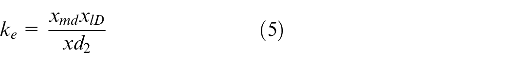


and


Hence, the stator flux linkage model can be represented as equations (11) and (12)


The sub-transient voltage can be written as equations (13) and (14) considering the above definitions,
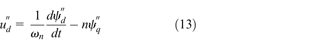
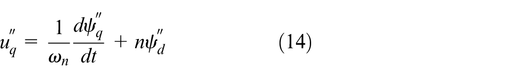
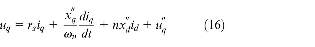
Now, stator equations using sub-transient voltage and stator current can be defined. Equations (15)–(17) present the stator model. This model contains the stator current and sub-transient voltage


The proposed multi-microgrid model used the general load model in the PowerFactory. The technical details of the general load model can be found in the PowerFactory documentation. The voltage dependency of the load has been implemented using the three-term polynomial and can be represented as equations (18) and (19). The “0” is the operating point.
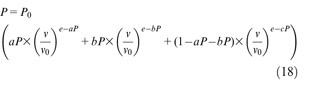
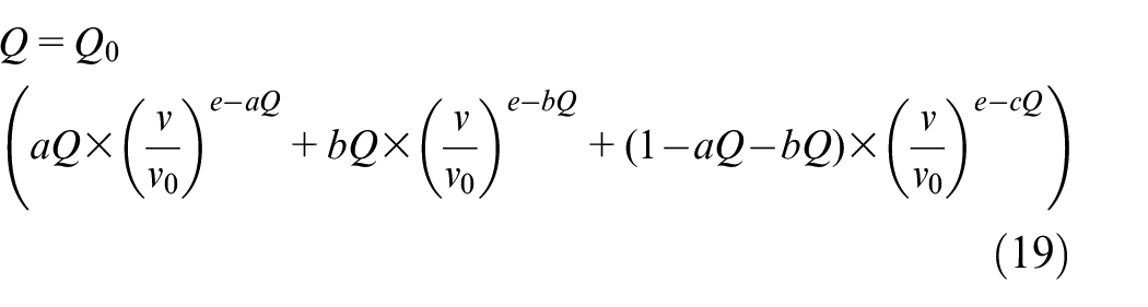
Where
The proposed multi-microgrid model used the cables for all three transmission lines. These lines were modeled using the PowerFactory technical documentation cable. Impedance Z and admittance Y can be represented as


Where


If
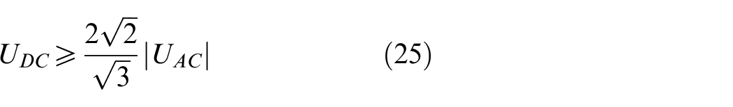
UPFC can be developed using the two PWM-based VSCs. One converter is the shunt converter and the other is the series converter. These converters are interlinked with a common DC-Node. The AC side of each converter is connected to the respective transformers. DC node contains the DC link capacitor. The working of the series converter is similar to the series static synchronous compensator (SSSC) and the working of the shunt converter is similar to the static synchronous compensator (STATCOM). Hence, UPFC worked with the coordinated control of these two PWM converters.
Results and discussion
This paper evaluates the transient stability of the alternative multi-microgrids (MMGs) using a PV system, wind power system, and UPFC. This section presents the key results based on the thorough experimentation in the DIgSILENT PowerFactory software. In the first step, the load flow calculation was performed for all the cases. DIgSILENT PowerFactory software exhibited that the load flow calculation was successful and all the control conditions were fulfilled. Then, the transient stability analysis was performed, which has been discussed in the following.
Transient stability of PV systems in multi-microgrid
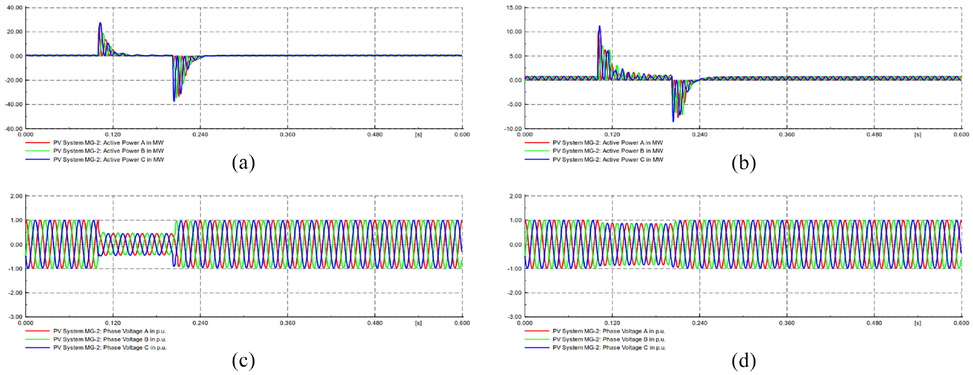
In this section, the key results have been presented for PV generators and busbars. The electromagnetic transients (EMT) simulation was performed in the presence and absence of UPFC in the grid-connected and disconnected modes. In the absence of UPFC, the load areas of microgrid-1 (i.e. MG-1) and microgrid-2 (i.e. MG-2) were identical. Figure 3 presents the active power stability of PV systems in the proposed multi-microgrid. In Case 1, UPFC was not used in the simulation model and the short circuit fault was not included considering the grid-connected mode. In this case, the smooth power flow was observed and the active power remained stable at approximately 0.80 MW as shown in Figure 3(a). Also, the phase voltage remained stable as shown in Figure 4(a). In Case 2, a short circuit was introduced and UPFC was not used in the grid-connected mode. In this case, Figure 3(b) and (c) present the active power flow for the MG-1 and MG-2. In this case, severe peaks and troughs can be observed. In Case 3, a short circuit was introduced and UPFC was added in the grid-connected mode. In this case, Figure 3(d) and (e) present the active power flow for the MG-1 and MG-2. In this case, the severe troughs in the active power flow have been significantly reduced by UPFC. Hence, UPFC has significantly stabilized the power flow in the multi-microgrid in the grid-connected mode.
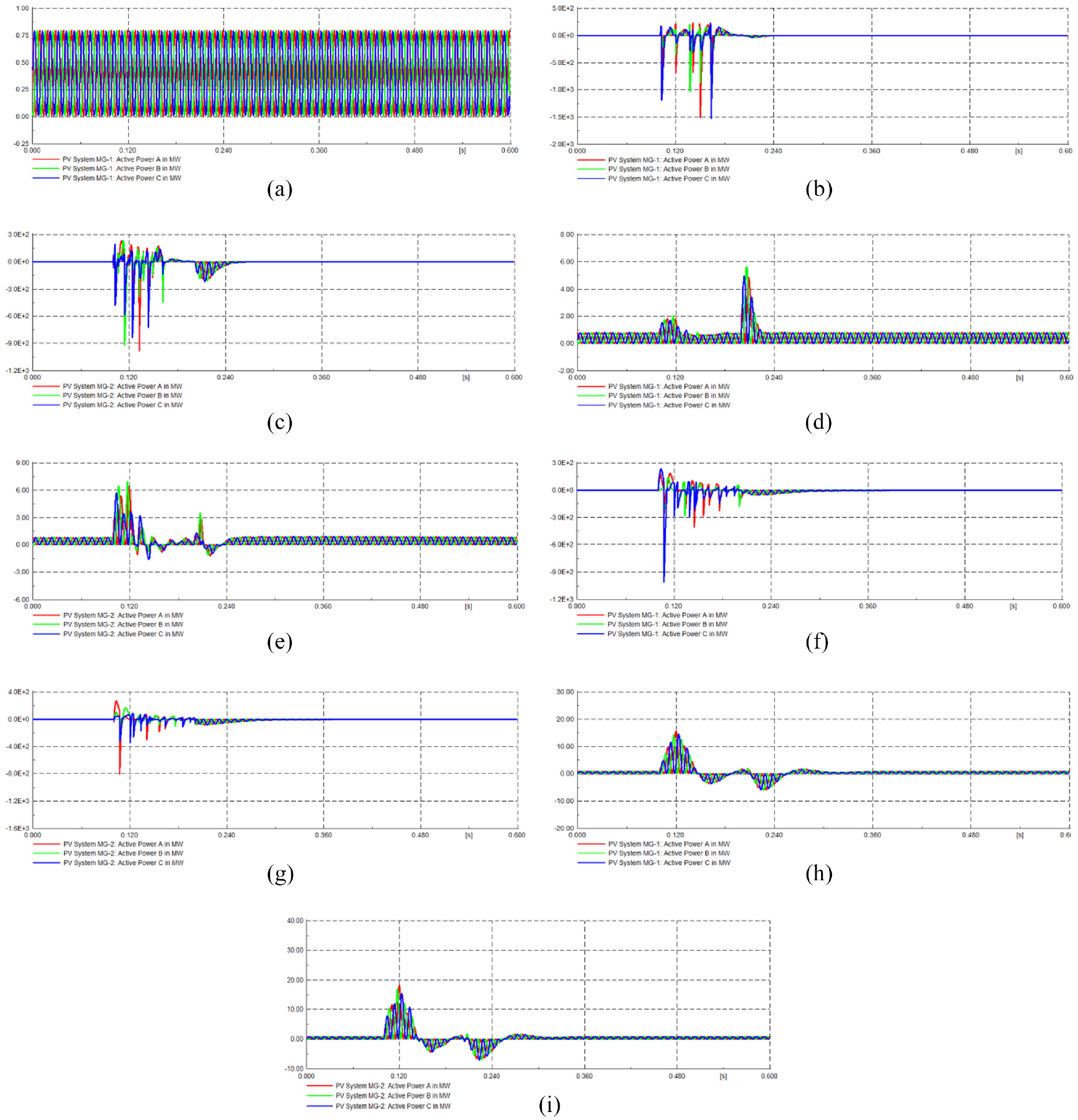
Active power at PV Systems in multi-microgrid: (a) Case 1. Grid connected, no UPFC, no short circuit at MG-1, (b) Case 2. Grid connected, no UPFC, one short circuit at MG-1, (c) Case 2. Grid connected, no UPFC, one short circuit at MG-2, (d) Case 3. Grid connected, UPFC used, one short circuit at MG-1, (e) Case 3. Grid connected, UPFC used, one short circuit at MG-2, (f) Case 5. Grid Disconnected, no UPFC, one short circuit at MG-1, (g) Case 5. Grid Disconnected, no UPFC, one short circuit at MG-2, (h) Case 6. Grid Disconnected, UPFC used, one short circuit at MG-1, and (i) Case 6. Grid Disconnected, UPFC used, one short circuit at MG-2.
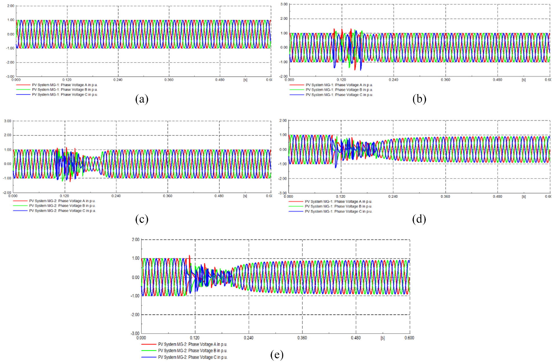
Phase voltage (per-unit or p.u.) at PV Systems in multi-microgrid: (a) case 1. Grid connected, no UPFC, no short circuit at MG-1, (b) case 2. Grid connected, no UPFC, one short circuit at MG-1, (c) case 2. Grid connected, no UPFC, one short circuit at MG-2, (d) case 5. Grid Disconnected, no UPFC, one short circuit at MG-1, and (e) case 5. Grid Disconnected, no UPFC, one short circuit at MG-2.
In the next three cases, the above analysis was performed in the grid-disconnected mode. In Case 4, UPFC was not used in the simulation model and the short circuit fault was not included considering the grid-disconnected mode. In this case, the power flow and phase voltage was the same as in Case 1. In Case 5, a short circuit was introduced and UPFC was not used in the grid disconnected mode. In this case, Figure 3(f) and (g) present the active power flow for the MG-1 and MG-2. In this case, severe peaks and troughs can be observed. In Case 6, a short circuit was introduced and UPFC was added in the grid disconnected mode. In this case, Figure 3(h) and (i) present the active power flow for the MG-1 and MG-2. In this case, the severe troughs in the active power flow have been considerably decreased by UPFC. Hence, UPFC has significantly stabilized the power flow in the multi-microgrid in the grid-disconnected mode.
In Case 2, a slight phase voltage fluctuation was observed at MG-1 as shown in Figure 4(b), and comparatively more phase voltage fluctuation was observed at MG-2 (Figure 4(c)). However, these fluctuations were completely absent in the presence of UPFC (i.e. Case 3). Similar voltage trends were observed in the grid-disconnection mode (i.e. Case 5 and Case 6). These voltage patterns were based on PV system generators. For the PV system busbars (PV-Bus MG-1 and PV-Bus MG-2), the phase voltage patterns were similar to the PV system generator values. However, the phase voltage values at busbars were smaller than the generator voltage for all the simulation trials.
Transient stability of wind systems in multi-microgrid
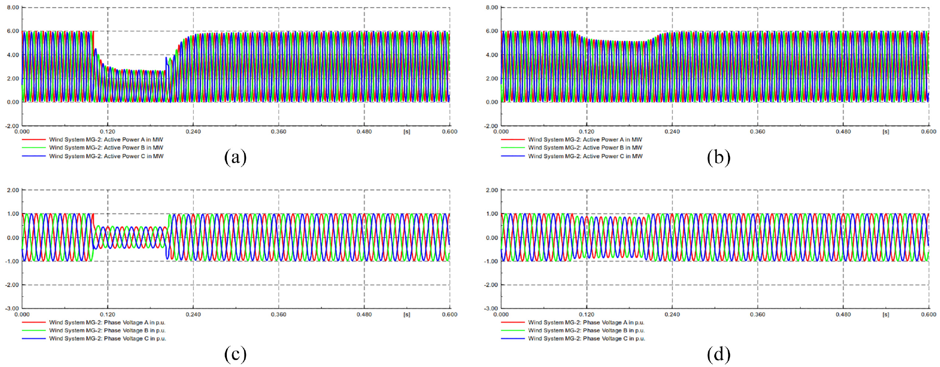
In this section, the key results have been presented for wind systems and associated busbars. Figure 5 presents the active power stability of wind systems in the proposed multi-microgrid. In Case 1, UPFC was not used in the simulation model and the short circuit fault was not included considering the grid-connected mode. In this case, the smooth power flow was observed and the active power remained stable at approximately 6 MW as shown in Figure 5(a). Also, the phase voltage remained stable similar to the corresponding case in PV systems (i.e. Figure 4(a)). In Case 2, a short circuit was introduced and UPFC was not used in the grid-connected mode. In this case, Figure 5(b) and (c) present the active power flow for the MG-1 and MG-2, respectively. In this case, MG-2 exhibited a more severe power flow fluctuation compared with MG-1. In Case 3, a short circuit was introduced and UPFC was added in the grid-connected mode. In this case, the active power flow remained completely stable as in Case 1. Hence, UPFC has significantly stabilized the power flow in the multi-microgrid in the grid-connected mode.
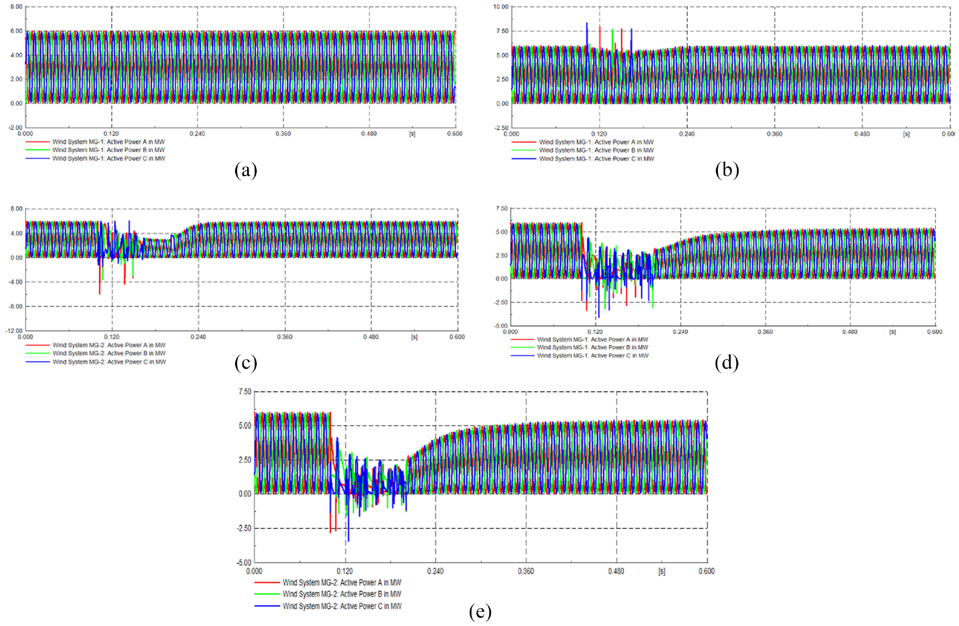
Active power at wind systems in multi-microgrid: (a) Case 1. Grid connected, no UPFC, no short circuit at MG-1, (b) Case 2. Grid connected, no UPFC, one short circuit at MG-1, (c) Case 2. Grid connected, no UPFC, one short circuit at MG-2, (d) Case 5. Grid Disconnected, no UPFC, one short circuit at MG-1, and (e) Case 5. Grid Disconnected, no UPFC, one short circuit at MG-2.
In the next three cases, the above analysis was performed in the grid-disconnected mode. In Case 4, UPFC was not used in the simulation model and the short circuit fault was not included considering the grid-disconnected mode. In this case, the power flow and phase voltage was the same as in Case 1. In Case 5, a short circuit was introduced and UPFC was not used in the grid disconnected mode. In this case, Figure 5(d) and (e) present the active power flow for the MG-1 and MG-2. In this case, more severe peaks and troughs can be observed compared with the grid-connection mode. In Case 6, a short circuit was introduced and UPFC was added in the grid disconnected mode. In this case, the active power flow remained completely stable as in Case 1. Hence, UPFC has significantly stabilized the power flow in the multi-microgrid in the grid-disconnected mode.
In Case 2, a slight phase voltage fluctuation was observed at MG-1 (Figure 6(a)), and comparatively more phase voltage fluctuation was observed at MG-2 (Figure 6(b)). However, these fluctuations were completely absent in the presence of UPFC (i.e. Case 3). Similar voltage trends were observed in the grid-disconnection mode (i.e. Case 5 and Case 6). However, the phase voltage variation was more in Case 5 as shown in Figure 6(c) and (d). These voltage patterns were based on wind system generators. For the wind system busbars (Wind-Bus MG-1 and Wind-Bus MG-2), the phase voltage patterns were similar to the PV system generator values. However, the phase voltage values at busbars were smaller than the generator voltage for all the simulation trials.
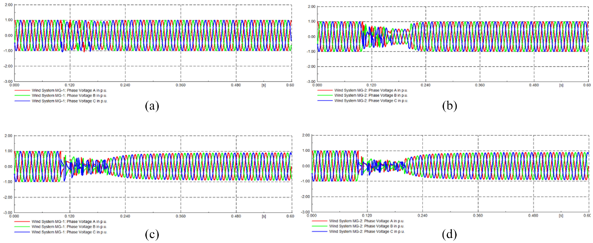
Phase voltage for wind systems: (a) Case 2. Grid connected, no UPFC, one short circuit at MG-1, (b) Case 2. Grid connected, no UPFC, one short circuit at MG-2, (c) Case 5. Grid Disconnected, no UPFC, one short circuit at MG-1, and (d) Case 5. Grid Disconnected, no UPFC, one short circuit at MG-2.
Transient stability of synchronous generators in multi-microgrid
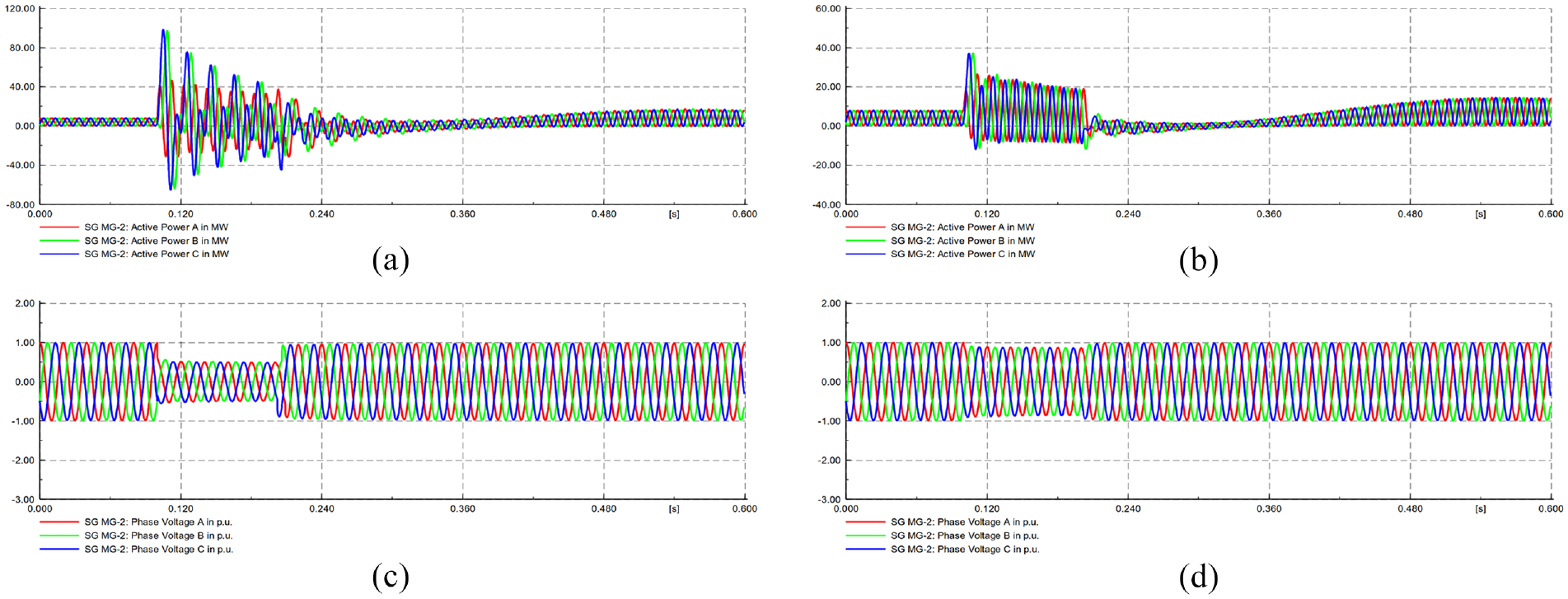
In this section, the key results have been presented for synchronous generators and related busbars. Figure 7 presents the active power stability of synchronous generators. In Case 1, UPFC was not used in the simulation model and the short circuit fault was not included considering the grid-connected mode. In this case, the smooth power flow was observed and the active power remained stable at approximately 8 MW as shown in Figure 7(a). Also, the phase voltage remained stable similar to the corresponding case in PV systems (i.e. Figure 4(a)). In Case 2, a short circuit was introduced and UPFC was not used in the grid-connected mode. In this case, Figure 7(b) and (c) present the active power flow for the MG-1 and MG-2. In this case, severe peaks and troughs can be observed. In Case 3, the short circuit was introduced and UPFC was added in the grid-connected mode. In this case, Figure 7(d) and (e) present the active power flow for the MG-1 and MG-2. In this case, MG-1 exhibited more stability compared with MG-2. Still, the UPFC significantly reduced the power flow fluctuations in MG-1.
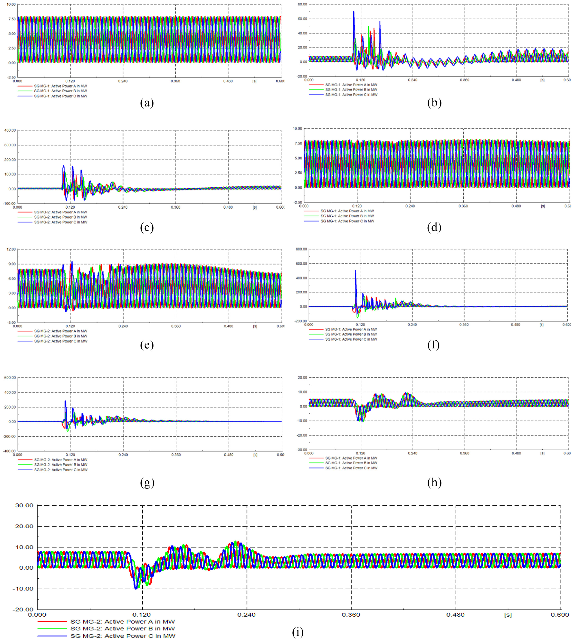
Active power at synchronous generator in multi-microgrid. (a) Case 1. Grid connected, no UPFC, no short circuit at MG-1, (b) Case 2. Grid connected, no UPFC, one short circuit at MG-1, (c) Case 2. Grid connected, no UPFC, one short circuit at MG-2, (d) Case 3. Grid Connected, UPFC used, one short circuit at MG-1, (e) Case 3. Grid Connected, UPFC used, one short circuit at MG-2, (f). Case 5. Grid disconnected, no UPFC, one short circuit at MG-1, (g) Case 5. Grid disconnected, no UPFC, one short circuit at MG-2, (h) Case 6. Grid disconnected, UPFC used, one short circuit at MG-1, and (i) Case 6. Grid disconnected, UPFC used, one short circuit at MG-2.
In the next three cases, the above analysis was performed in the grid-disconnected mode. In Case 4, UPFC was not used in the simulation model and the short circuit fault was not included considering the grid-disconnected mode. In this case, the power flow and phase voltage were the same as in Case 1. In Case 5, the short circuit was introduced and UPFC was not used in the grid disconnected mode. In this case, Figure 7(f) and (g) present the active power flow for the MG-1 and MG-2. In this case, more severe peaks and troughs can be observed compared with the grid-connected mode. In Case 6, the short circuit was introduced and UPFC was added in the grid disconnected mode. In this case, Figure 7(h) and (i) present the active power flow for the MG-1 and MG-2. In this case, the severe troughs and peaks in the active power flow have been reduced by UPFC. Hence, UPFC has significantly stabilized the power flow in the multi-microgrid in the grid-disconnected mode.
In Case 2, a slight phase voltage fluctuation was observed at MG-1 (Figure 8(a)), and comparatively more voltage fluctuation was observed at MG-2 (Figure 8(b)). However, these fluctuations were completely absent in the presence of UPFC (i.e. Case 3). Similar voltage trends were observed in the grid-disconnection mode (i.e. Case 5 and Case 6). However, the phase voltage variation was more in Case 5. These voltage patterns were based on the synchronous generators. For the related busbars (SG-Bus MG-1 and SG-Bus MG-2), the phase voltage patterns were similar to the PV system generator values. However, the phase voltage values at these busbars were smaller than the generator voltage for all the simulation trials.
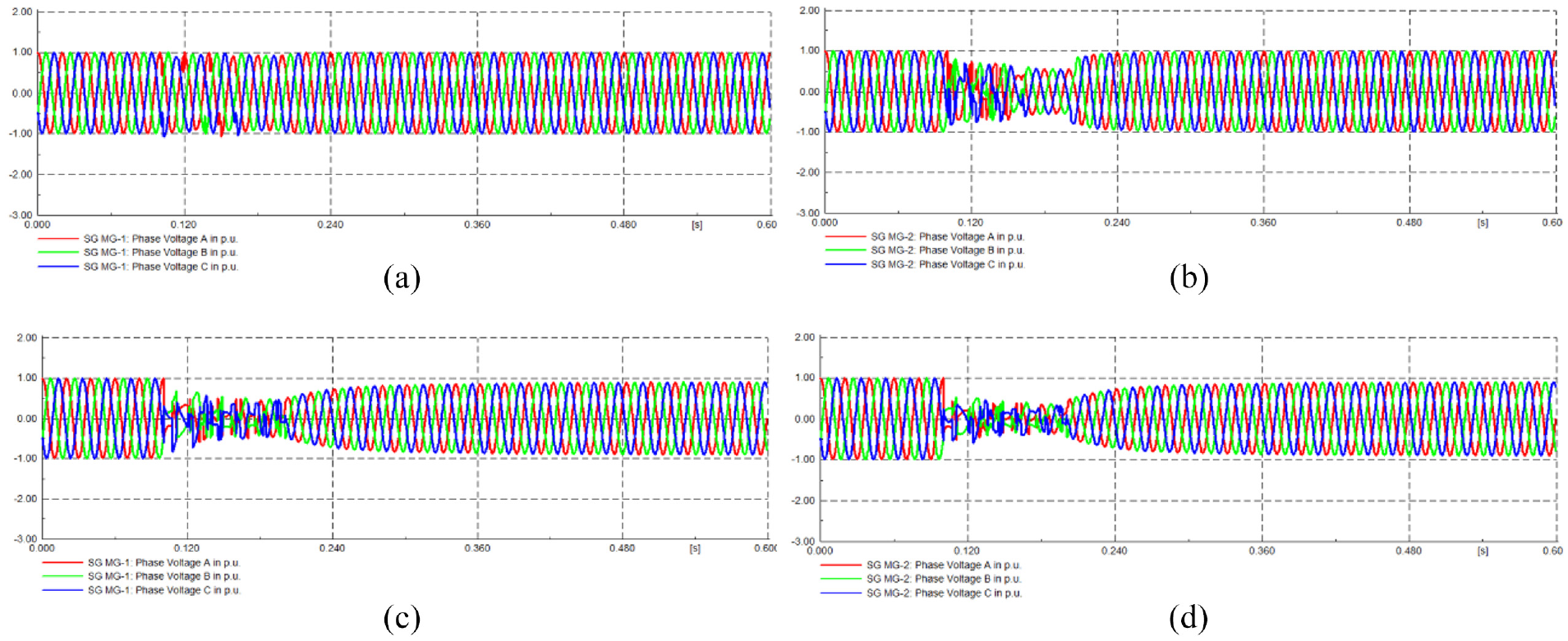
Phase voltage (per-unit or p.u.) at synchronous generators in multi-microgrid: (a) Case 2. Grid connected, no UPFC, one short circuit at MG-1, (b) Case 2. Grid connected, no UPFC, one short circuit at MG-2, (c) Case 5. Grid Disconnected, no UPFC, one short circuit at MG-1, and (d) Case 5. Grid Disconnected, no UPFC, one short circuit at MG-2.
Transient stability of demand loads in multi-microgrid
In this section, the key results have been presented for the demand loads and related busbars. Figure 9 presents the active power stability of the demand loads. In Case 1, UPFC was not used in the simulation model and the short circuit fault was not included considering the grid-connected mode. In this case, the smooth power flow was observed and the active power remained stable at approximately 13.3 MW as shown in Figure 9(a). Also, the phase voltage remained stable similar to the corresponding case in PV systems (i.e. Figure 4(a)). In Case 2, a short circuit was introduced and UPFC was not used in the grid-connected mode. In this case, Figure 9(b) and (c) present the active power flow for the MG-1 and MG-2. In this case, the active power was slightly decreased in the load of MG-1 but it became zero in the load of MG-2 during the short circuit. In this case, phase voltage slightly fluctuated in the MG-1 (Figure 10(a)) but it was zero in the load of MG-2 during the short circuit (Figure 10(b)). In Case 3, a short circuit was introduced and UPFC was added in the grid-connected mode. In this case, the active power and phase voltage fluctuations were completely removed in the case of the MG-1 load. The active power and phase voltage for the MG-2 load remained almost the same as in Case 2 during the short circuit. Hence, the UPFC reduced the power flow fluctuations in MG-1.
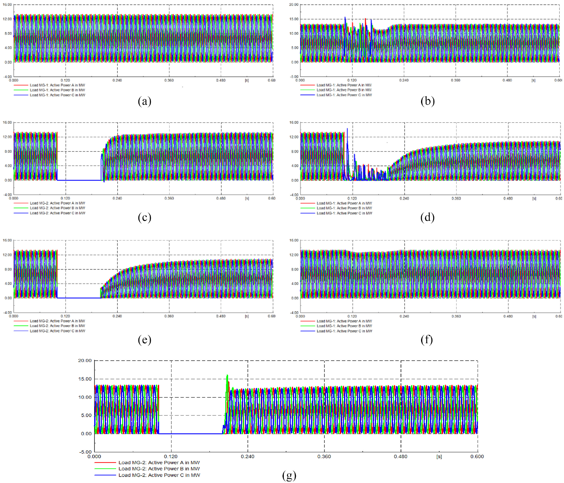
Active power at loads in multi-microgrid: (a) Case 1. Grid connected, no UPFC, and no short circuit at MG-1,. (b) Case 2. Grid connected, no UPFC, and one short circuit at MG-1, (c) Case 2. Grid connected, no UPFC, and one short circuit at MG-2, (d) Case 5. Grid disconnected, no UPFC, and one short circuit at MG-1, (e) Case 5. Grid disconnected, no UPFC, and one short circuit at MG-2, (f) Case 6. Grid disconnected, UPFC used, and one short circuit at MG-1, and (g) Case 6. Grid disconnected, UPFC used, and one short circuit at MG-2.
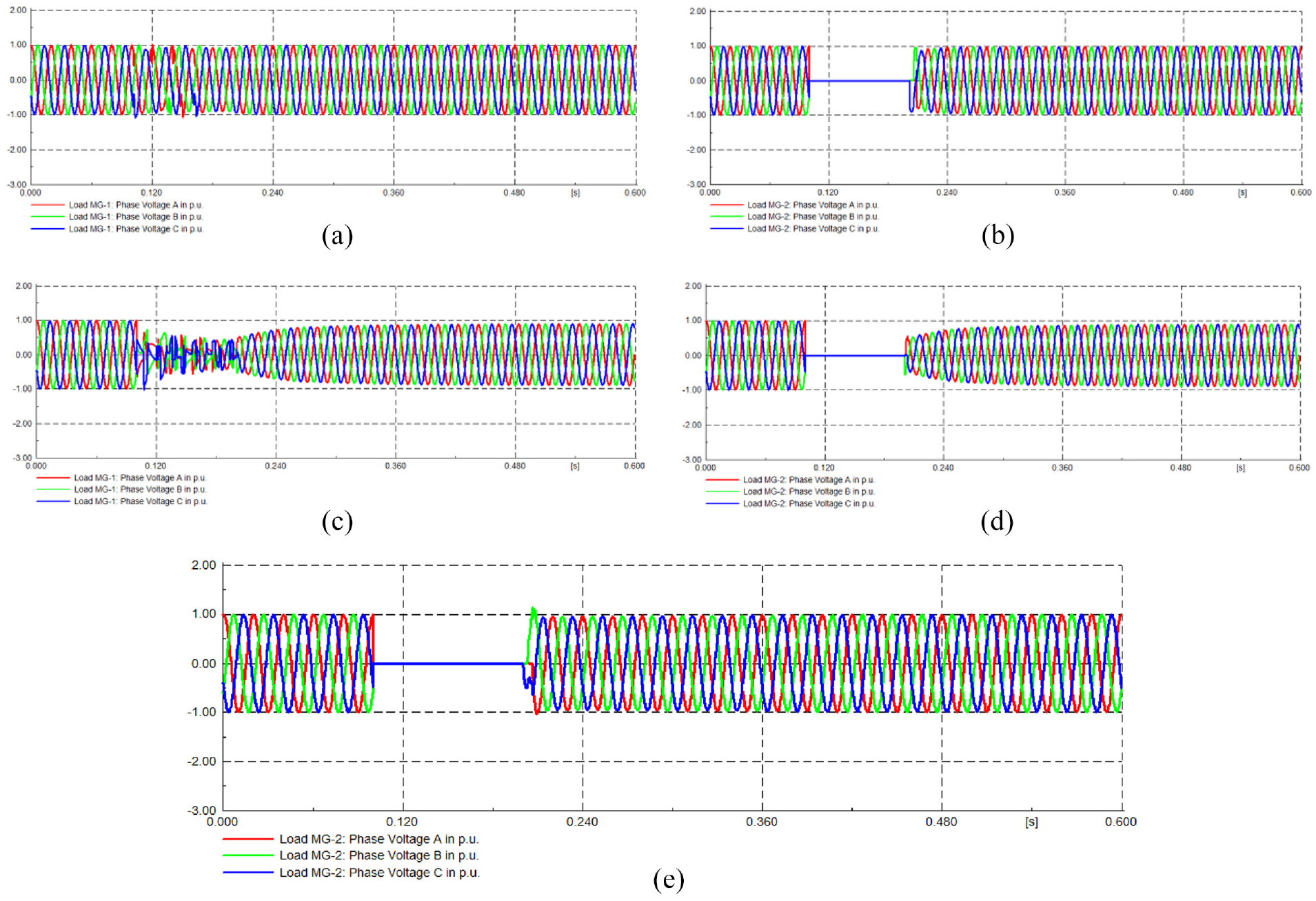
Phase voltage at loads in multi-microgrid: (a) Case 2. Grid connected, no UPFC, and one short circuit at MG-1, (b) Case 2. Grid connected, no UPFC, and one short circuit at MG-2, (c) Case 5. Grid disconnected, no UPFC, and one short circuit at MG-1, (d) Case 5. Grid disconnected, no UPFC, and one short circuit at MG-2, and (e) Case 6. Grid disconnected, UPFC used, and one short circuit at MG-2.
In the next three cases, the above analysis was performed in the grid-disconnected mode. In Case 4, UPFC was not used in the simulation model and the short circuit fault was not included considering the grid-disconnected mode. In this case, the power flow and phase voltage were the same as in Case 1. In Case 5, the short circuit was introduced and UPFC was not used in the grid disconnected mode. In this case, Figure 9(d) and (e) present the active power flow for the MG-1 and MG-2. In this case, the active power flow was reduced significantly for both microgrids. In addition, phase voltage decreased in the case of MG-1 load (Figure 10(c)) and it became zero for MG-2 (Figure 10(d)) during the short circuit. In Case 6, the short circuit was introduced and UPFC was added in the grid disconnected mode. In this case, Figure 9(f) and (g) present the active power flow for the MG-1 and MG-2. In this case, the active power has been stabilized for the MG-1 during and after the fault. Also, the active power has been stabilized for MG-2 after the fault. In addition, phase voltage fluctuation was eliminated in the case of MG-1 load and it was maintained for MG-2 (Figure 10(e)) after the short circuit clearance. Hence, UPFC has significantly stabilized the power flow and phase voltage in the multi-microgrid in the grid-disconnected mode. The above voltage patterns were based on the final load location. For the related busbars, the phase voltage patterns were similar to the load locations. However, the phase voltage values at these busbars were smaller than the load locations for all the simulation trials.
Transient stability of two main busbars
In this section, the key results have been presented for the two main busbars in a multi-microgrid. Figure 11 presents the voltage stability of these two main busbars. In Case 1, UPFC was not used in the simulation model and the short circuit fault was not included considering the grid-connected mode. In this case, the phase voltage remained stable as shown in Figure 11(a). In Case 2, a short circuit was introduced and UPFC was not used in the grid-connected mode. In this case, Figure 11(b) and (c) present the short circuit current for the MG-1 and MG-2. In this case, the phase voltage slightly decreased in the MG-1 but it significantly dropped in the case of the main busbar at MG-2 during the short circuit. In Case 3, a short circuit was introduced and UPFC was added in the grid-connected mode. In this case, the phase voltage fluctuations were completely removed for both microgrids. Hence, the UPFC eliminated the voltage fluctuations in the main busbars of the multi-microgrid.
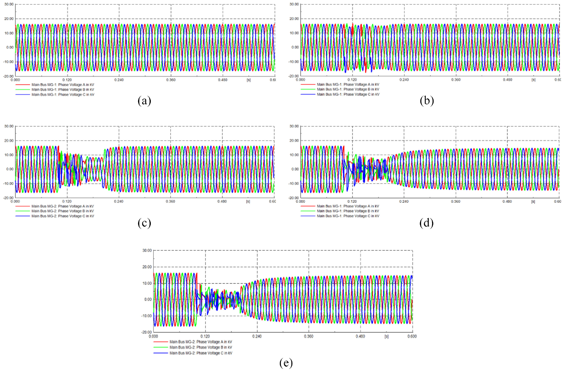
Transient analysis at two main busbars in multi-microgrid: (a) Case 1. Grid connected, no UPFC, and no short circuit at MG-1, (b) Case 2. Grid connected, no UPFC, and one short circuit at MG-1, (c) Case 2. Grid connected, no UPFC, and one short circuit at MG-2, (d) Grid disconnected, no UPFC, and one short circuit at MG-1, and (e) Case 6. disconnected, no UPFC, and one short circuit at MG-2.
In Case 4, UPFC was not used in the simulation model and the short circuit fault was not included considering the grid-disconnected mode. In this case, the phase voltage was the same as in Figure 11(a). In Case 5, a short circuit was introduced and UPFC was not used in the grid disconnected mode. In this case, Figure 11(d) and (e) present the active power flow for the MG-1 and MG-2. In this case, the phase voltage faced severe voltage drops during and after the fault. In Case 6, the short circuit was introduced and UPFC was added in the grid disconnected mode. In this case, the phase voltage fluctuations were completely removed for both microgrids. Hence, the UPFC eliminated the voltage fluctuations in the main busbars of the multi-microgrid.
Short circuit current at the affected busbar
In this section, the key results have been presented for the busbar with a short circuit (i.e. Load Bus-2 MG-2). Figure 12 presents the short circuit current at the affected busbars. In Case 1, UPFC was not used in the simulation model and the short circuit fault was not included considering the grid-connected mode. In this case, the short circuit current remained zero as shown in Figure 12(a). In Case 2, the short circuit was introduced and UPFC was not used in the grid-connected mode. In this case, Figure 12(b) presents the short circuit current for the affected busbar. In this case, severe short-circuit current fluctuations (i.e. up to 53 kA) were observed. In Case 3, the short circuit was introduced and UPFC was added in the grid-connected mode. In this case, a short circuit current was observed maximum of up to 1.6 kA (Figure 12(c)). In Case 4, UPFC was not used in the simulation model and the short circuit fault was not included considering the grid-disconnected mode. In this case, the results were the same as in Figure 12(a). In Case 5, the short circuit was introduced and UPFC was not used in the grid disconnected mode. In this case, Figure 12(d) presents the short circuit current for the affected busbar. In this case, the severe short circuit current fluctuations (i.e. up to 33 kA). In Case 6, a short circuit was introduced and UPFC was added in the grid-connected mode. In this case, a short circuit current was observed maximum of up to 1.6 kA (Figure 12(e)). It can be concluded that the UPFC has significantly eliminated the short circuit current in the affected busbar in the multi-microgrid.
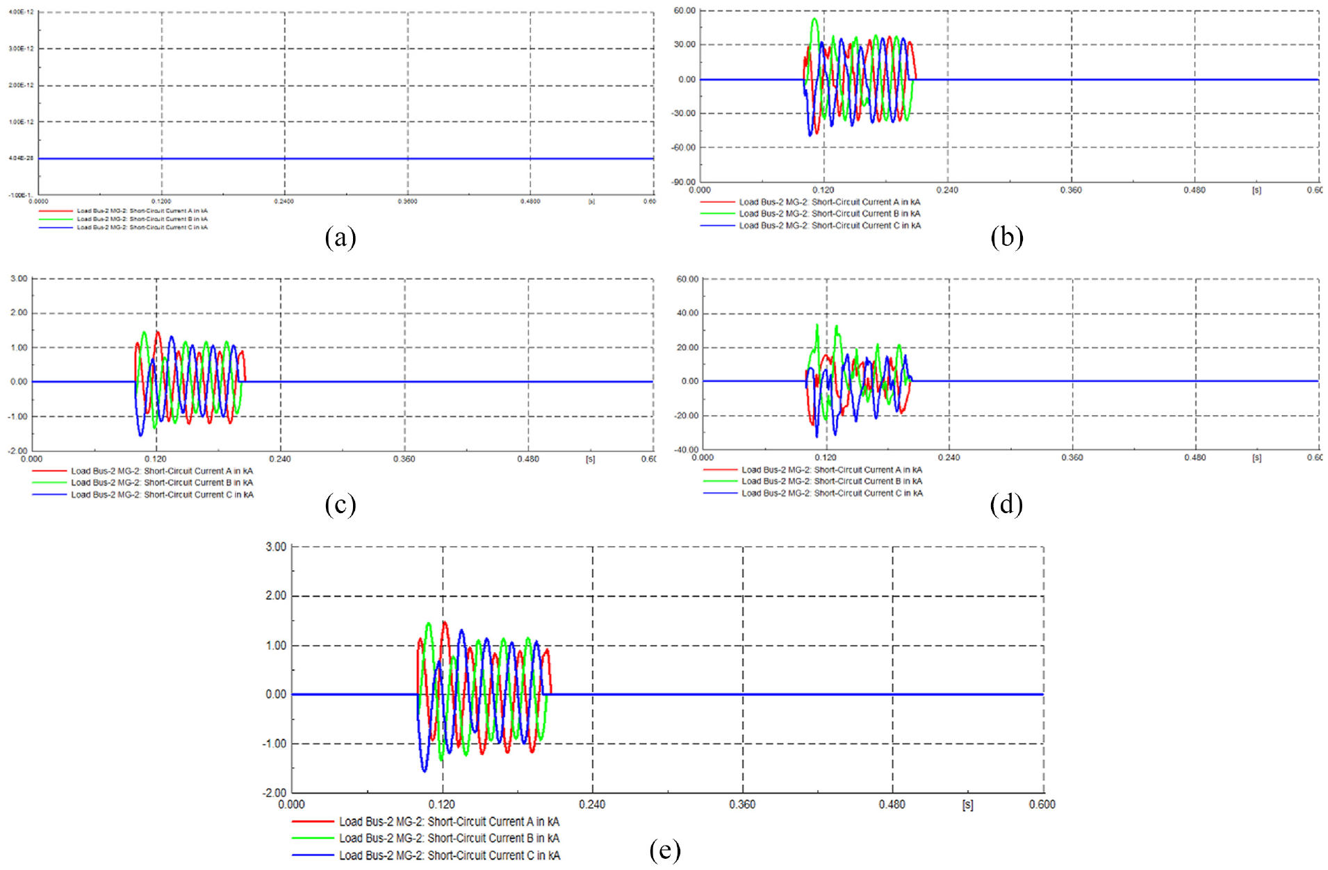
Short-circuit current at different busbars in multi-microgrid: (a).Case 1. Grid connected, no UPFC, and no short circuit at MG-1, (b) Case 2. Grid connected, no UPFC, and one short circuit at MG-2, (c) Case 3. Grid connected, UPFC used, and one short circuit at MG-2, (d) Case 5. Grid disconnected, no UPFC, and one short circuit at MG-2, and (e) Case 6. Grid disconnected, UPFC used, and one short circuit at MG-2.
Short circuit faults at both microgrids
In the previous sections, all the results are based on the presence of the short circuit at only one microgrid. In this section, the short circuit has been introduced at both microgrids with the same duration and location of the short circuit as in the case of a single microgrid in the previous analysis. In the following, the short circuit analysis has been performed for Case 2 (Grid connected, no UPFC, and one short circuit) and Case 3 (Grid connected, UPFC used, and one short circuit). Only the difference is the inclusion of the two short circuits. Figure 13 presents the short circuit current for both short circuits at both microgrids. It can be observed that the short circuit current is almost the same for microgrid-1 in the absence (Figure 13(a)) and presence (Figure 13(b)) of UPFC. Since UPFC was located in microgrid-2; it did not work well for microgrid-1 where it was not located. In the case of microgrid-2, the short circuit current was significantly reduced in the presence of UPFC (Figure 13(d)) compared with the absence of UPFC (Figure 13(c)). Hence, UPFC worked more efficiently when it was located near the location with short circuits.
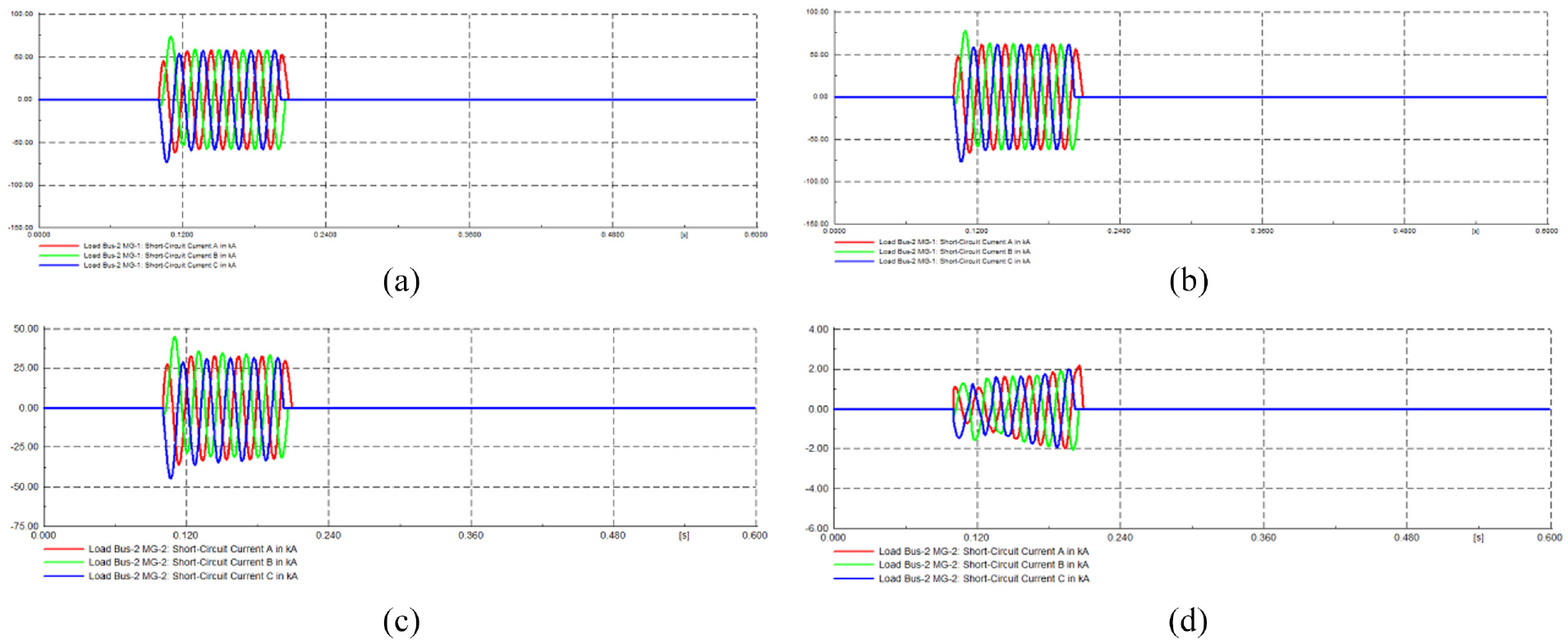
Short circuit current if short circuits observed at both microgrids: (a) grid connected, no UPFC, Microgrid-1, (b) grid connected, UPFC used, Microgrid-1, (c) grid connected, no UPFC, Microgrid-2, and (d) grid connected, UPFC used, Microgrid-2.
Figure 14 presents the phase voltage at the main busbar for microgrid-2. It was observed that the phase voltage was not much affected for microgrid-1 in the presence and absence of UPFC. Hence, the figures for microgrid-1 were skipped. For microgrid-2, the phase voltage was significantly reduced in the presence of UPFC (Figure 14(b)) compared with the absence of UPFC (Figure 14(a)).
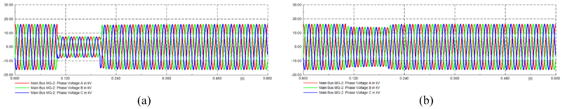
Phase voltage at the main busbar if short circuits observed at both microgrids: (a) grid connected, no UPFC, Microgrid 2 and (b) grid connected, UPFC used, Microgrid 2.
Figure 15 presents the active power and phase voltage at microgrid-2 for the synchronous generator. It was observed that the active power and phase voltage was not much affected for microgrid-1 in the presence and absence of UPFC. In the case of microgrid-2, the active power and phase voltage was significantly improved in the presence of UPFC (Figure 15(b)) compared with the absence of UPFC (Figure 15(a)).
Active power and phase voltage at synchronous generators if short circuits observed at both microgrids: (a) grid connected, no UPFC, Microgrid 2 and (b) grid connected, UPFC used, Microgrid 2.
Figure 16 presents the active power and phase voltage at microgrid-2 for PV System. It was observed that the active power and phase voltage was not much affected for microgrid-1 in the presence and absence of UPFC. For the microgrid-2, the active power and phase voltage was significantly improved in the presence of UPFC (Figure 16(b)) compared with the absence of UPFC (Figure 16(a)).
Active power and phase voltage at PV systems if short circuits observed at both microgrids: (a) grid connected, no UPFC, Microgrid 2 and (b) grid connected, UPFC used, Microgrid 2.
Figure 17 presents the active power and phase voltage at microgrid-2 for the wind System. It was observed that the active power and phase voltage was not much affected for microgrid-1 in the presence and absence of UPFC. For the microgrid-2, the active power and phase voltage was significantly improved in the presence of UPFC (Figure 17(b)) compared with the absence of UPFC (Figure 17(a)).
Active power and phase voltage at wind systems if short circuits observed at both microgrids: (a) grid connected, no UPFC, Microgrid 2 and (b) grid connected, UPFC used, Microgrid 2.
Conclusion
This paper performs the transient stability analysis for multi-microgrids (MMG) based on the integration of UPFC and renewable energy under several possible circumstances. It can be concluded that the UPFC would greatly help in the quick fault clearance and transient stability in MMGs. It was observed that UPFC worked more efficiently for the nearby power system components. However, its positive effect was observed in both microgrids. For the optimal working of UPFC, its parameters should be reconfigured. However, any optimal design cannot be fixed due to the power flow dynamics including renewable energy fluctuations and unexpected faults. In this case, the working of UPFC should be flexible in the case of any fault. It can also be concluded that a single UPFC can be designed for both the grid-connected and disconnected modes. Future research may extend this work in several directions. For instance, the comprehensive analysis of multi-microgrids can be performed in the presence of storage, overloading, and the different types of failures at different locations in the multi-microgrids. All of these problems would involve complex modifications in the multi-microgrid system. From the personal experience of the authors, DIgSILENT PowerFactory software was found very easy, flexible, accurate, and efficient for the power system analysis in the smart grids. However, there are immense opportunities for scientists and scholars to use and improve this software for the analysis of advanced power systems. The use of such specialized software would dramatically accelerate the accurate solutions to the transient stability and other related problems in the smart grids. Moreover, future research may include more than two MMGs in the analysis. Other renewable energy resources (e.g. biogas, solar thermal, hydropower, geothermal, and Tidal energy) can be added to the analysis. In addition, the other various power flow controllers would be evaluated in the analysis of MMGs. Power flow analysis is a most challenging and complex area in power system analysis research. In this context, the MMGs are the emerging networks leading to additional challenges and complexity in the power flow analysis. Hence, the power flow analysis of the MMGs is a promising research area that needs extensive research in different directions.
Footnotes
Appendix
Acknowledgements
The authors would like to acknowledge the support of the deanship of scientific research at Najran University, Ministry of Education, Kingdom of Saudi Arabia for this research through a grant (NU/ RG/SERC/12/29) under the Funding Committee of the deanship of scientific research at Najran University, Kingdom of Saudi Arabia.
Declaration of conflicting interests
The author(s) declared no potential conflicts of interest with respect to the research, authorship, and/or publication of this article.
Funding
The author(s) disclosed receipt of the following financial support for the research, authorship, and/or publication of this article: This research was supported by the Deanship of Scientific Research at Najran University through a grant (NU/ RG/SERC/12/29).