
Abstract
The use of maximum power point tracking (MPPT) technology has significantly increased the conversion efficiency of PV modules. However, the presence of partial shading in PV arrays can lead to multi-peaked output curves, which traditional MPPT methods struggle to track due to falling into local maximum power points. The paper proposes a MPPT control algorithm based on the combination of differential flat control (DFBC) and adaptive particle swarm optimization (APSO) algorithm. The PSO output value is used as the feed-forward feedback input of differential flat, and a second-order controller is used to track the reference flat trajectory, achieving global MPPT through differential flat control. The algorithm can overcome the system oscillation caused by the randomness of the PSO algorithm with the initialized particle position and the existence of control lag misjudgment. Simulation and experimental results show that the algorithm not only solves the problem that the traditional MPPT algorithm cannot find the global maximum power point, but also solves the problems that the traditional particle swarm algorithm has large randomness, slow convergence speed, and easy to produce large oscillations. The algorithm has greatly improved the tracking accuracy, tracking speed and response speed, realizing fast and accurate response to external changes, reducing energy loss, and improving the dynamic tracking performance of the system.
Introduction
With the increasing depletion of traditional fossil energy sources, clean and environmentally friendly solar energy has become an important part of the energy field. Photovoltaic cells are capable of converting solar energy into electrical energy, and when irradiance and temperature change, the output voltage and output current of Photovoltaic cells will change, exhibiting nonlinear output characteristics 1 In order to improve the conversion efficiency of the PV module, the PV module is always operated at the maximum power point by the corresponding control strategy, and this process is called maximum power point tracking (MPPT). MPPT technology has become an important part of PV systems and is very important to improve the conversion efficiency of PV modules. The commonly used MPPT methods are constant voltage (CVT) method, 2 perturbation observation (P&O)3,4 method, and conductance increment method (INC).5,6 These traditional methods cannot take into account the requirements of tracking time, tracking accuracy, and response speed due to their own limitations, and they are easy to fall into the local maximum power point in the shaded case and cannot track the global maximum power point, which causes great power loss. Therefore, the study of maximum power point tracking in the shaded case becomes especially important. 7
Many new approaches have been proposed to solve the multi-peak problem for this problem. Literature 8 uses a control strategy combining differential flat \right)control and perturbation observation method, but it requires initialization of the reference voltage and cannot accurately track the PV maximum power point under sudden changes in irradiance, so there are some limitations. Literature 9 proposed a combination of a sliding mode variable structure control and a perturbation observation method, but both methods have the potential to miss the maximum power point. Current research on maximum power tracking in shaded situations has focused on population intelligence optimization algorithms.10,11 Particle swarm algorithm, as a global algorithm with simple principle and strong global search capability, is widely used on MPPT.12,13 The literatures14,15 used particle swarm algorithm by introducing adaptive parameter algorithm and random particles, but there are problems such as large oscillation amplitude, slow convergence speed, and dependence on initial conditions.16,17 Literature 18 proposed a hybrid algorithm based on the perturbation observation method and PSO, while the tracking time can be reduced by more than 35% compared to the original PSO, but the system oscillates more and the tracking accuracy is not high.
Therefore, this paper proposes a differential flatness control & APSO based MPPT control algorithm. Differential flatness theory is a novel control method for nonlinear systems. 19 In this paper, the differential flattening theory is applied to the MPPT of PV system, and the APSO output value is used as the feedforward input of differential flattening, and the reference flat trajectory is tracked using a second-order controller, and finally the global MPPT is achieved by differential flattening control.
The rest of this paper is organized as follows: The second section introduces the model and characteristics of the photovoltaic system. The third section briefly describes the maximum power control algorithm of the photovoltaic system. The MPPT algorithm design for DFBC and APSO is provided in Section 4, followed by Section 5 Analysis of Experimental Results, finally, concluding remarks appear in Section 6.
Modeling and characterization of photovoltaic systems
Photovoltaic cell mathematical model
The equivalent circuit model of the solar cell is shown in Figure 1. Where the current source represents the photoreceptor current, which depends on the semiconductor material properties of the cell, the current source is connected in parallel with the diode and the equivalent parallel resistance

Where:
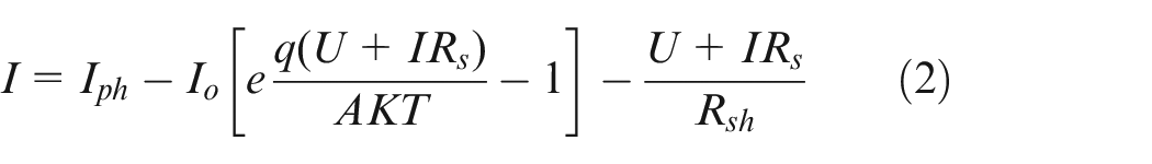
Where:
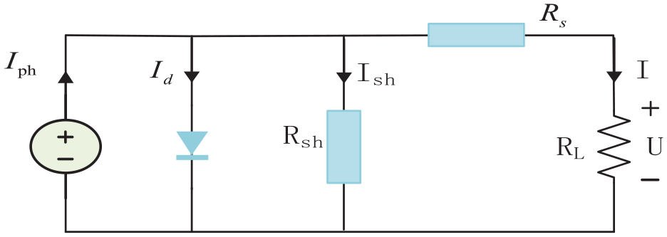
Equivalent circuit model of solar cell.
PV array output characteristics in complex shading environments
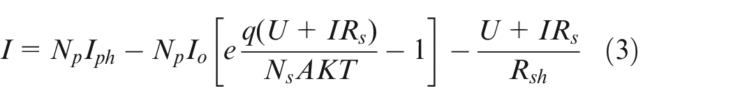
A photovoltaic array is a physical combination of solar PV modules connected in series and parallel several times. Let the PV array of M × N consists of
In the case of partial shading, the shaded PV module cannot generate electricity and becomes a load, which can lead to a hot spot effect, resulting in power loss and permanent damage to the PV module. To solve this problem, a bypass diode is usually connected in parallel at both ends of the PV module in practical engineering. When the PV array is under normal lighting conditions, each PV cell works normally and the bypass diode is in reverse cutoff at this time. When there is a part of the module is shaded, the bypass diode is in the conduction state at this time, short-circuiting the shaded module, preventing the current breakdown and playing a protective role, which also leads to the multi-peak characteristics of the PV P–U curve. When the PV array consists of multiple PV modules connected in series, the analysis process is the same as that for a single PV module.
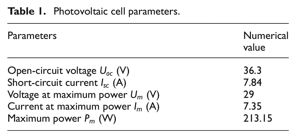
In this paper, the TCT structured PV array is built according to the PV cell parameters in Table 1. Firstly, 10 photovoltaic cells are connected in parallel to achieve the required output voltage, and then these strings are connected in series to ensure that the output voltage reaches the voltage range required for normal operating conditions, finally forming a photovoltaic array, the principle of photovoltaic array composition is shown in Figure 2.
Photovoltaic cell parameters.
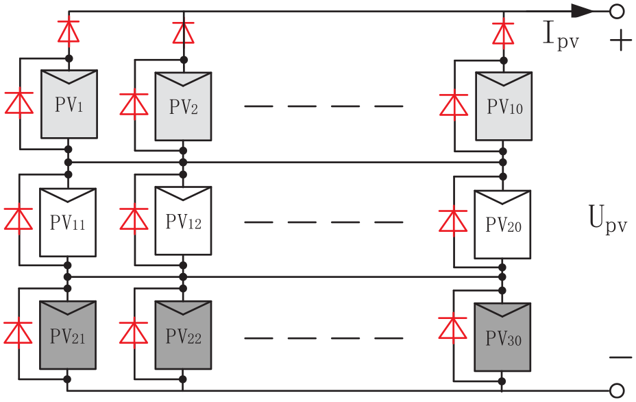
Photovoltaic array composition schematic.
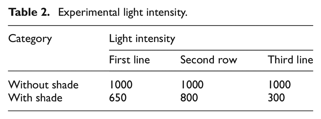
To simulate a shaded PV array, different light intensities were applied to rows 1–3 of the TCT structure to achieve the effect of a partially shaded PV array. Experiments were conducted according to the light intensity in Table 2 to study the output characteristics of the PV array under complex shading environment, and the output characteristic curves were obtained as shown in Figure 3.
Experimental light intensity.
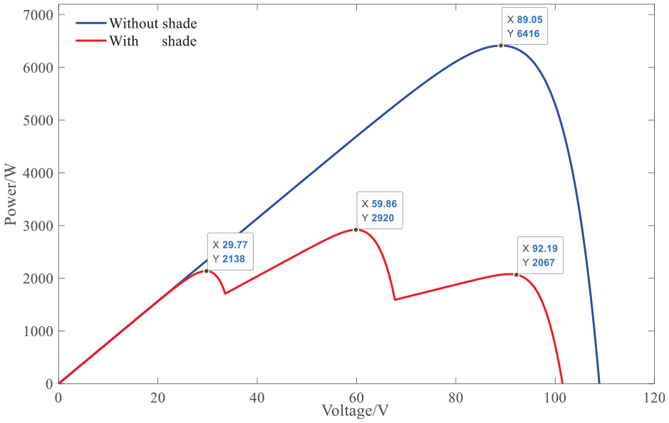
PV array P–U output characteristic curve.
As can be seen from Figure 3, the output power of the PV array has a nonlinear relationship with the output voltage and shows a single-peak characteristic in the unshaded environment, and with the change of light intensity, the PV array shows a multi-peak characteristic in the shaded environment. Although the output characteristics curve of photovoltaic cells show non-linear, but when the external environment remains unchanged, at a certain point there is bound to be an extreme value, the point is the maximum power point, and the voltage corresponding to it is the maximum power point voltage.
Single-phase PV array MPPT control system structure
From the above P–U characteristic curve of PV cell, we can see that adjusting the output voltage of PV cell, its power output will change accordingly. The maximum output power is obtained by controlling the output voltage of the PV cell so that it operates at that pole point, which is the principle of PV maximum power tracking. 21
The structure of the resulting single-phase PV MPPT control system is shown in Figure 4 and consists of four main parts: PV array modules consisting of PV cells connected in series and parallel to provide energy to the entire system. The controller module, based on the P–U output characteristics of the PV array, performs the MPPT control algorithm operation, and the algorithm output is used to control the duty cycle of the IGBT switches. Boost circuit, the control signal output by the controller according to the MPPT algorithm is loaded to the IGBT switch of the Boost circuit, which regulates the output voltage of the PV array by controlling the duty cycle of the IGBT, thus controlling the output power of the PV array for the purpose of maximum power tracking. A load module that converts the electrical energy generated by the PV array into other forms of energy for utilization.
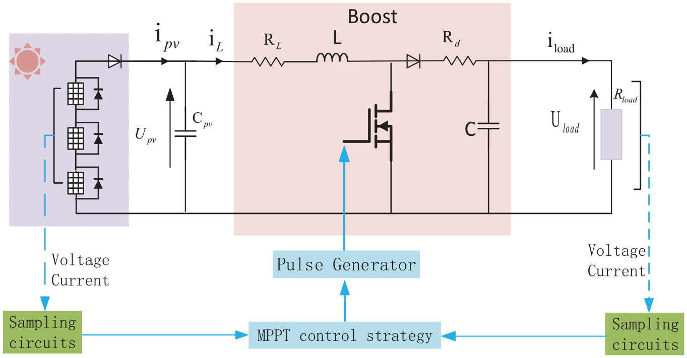
Sketch of MPPT control system structure of PV array.
Maximum power control algorithm for PV systems
PSO algorithm
In the case of PV arrays with shading, traditional MPPT algorithms such as constant voltage (CVT) method, perturbation observation (P&O) method, and conductivity increment method are prone to fall into the local maximum power point due to their own limitations, and cannot do global optimization search. To solve this problem, a particle swarm algorithm (PSO) algorithm can be introduced to perform the optimization search. The PSO algorithm is a meta-heuristic method that enables global optimization of multipole functions. Each particle in the particle swarm algorithm has three parameters, namely the current position, velocity, and direction of the particle. When alliterative updating the position of a particle, the position of each particle is determined by the current historical optimal value


Where,
APSO algorithm
The ordinary particle swarm algorithm is more sensitive to the initial conditions because of the fixed parameters. The learning factors
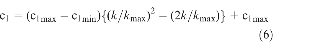
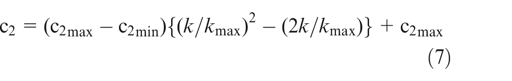
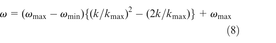
where:
The PSO algorithm have good performance in global optimization seeking, but some application studies in recent years have shown that particle swarm algorithms in the traditional sense substantially randomize the initialization of particle positions leading to system oscillations, while the actual algorithms have problems such as control lag misclassification. For this reason, some scholars at home and abroad began to try to combine the PSO algorithm with the traditional MPPT algorithm to solve the contradiction between tracking speed and tracking accuracy.
Differential flatness control
The differential flatness control theory (DFBC) was proposed by Martin in the form of differential algebra, then studied in depth by Fliess and others, and applied to control theory. 22 The system with differential flatness based control does not need to transform the nonlinear system into a linear system, and has better stability, tracking, and robustness. 23 In recent years, it has been gradually introduced into the control field of power generation, electric motors, power electronics, etc. 24
The basic meaning is that in a nonlinear system, if it is possible to find a set of output vectors and that set of output vectors and its finite order differential algebra can represent all the input vectors and state vectors of the system without any integration. Then this nonlinear system is considered to be flat and can be called differential flat system. For a better understanding, assuming that the nonlinear system state variable is
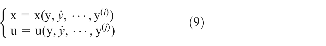
where
For differential flat systems, differential flat control theory can be used for control. The control principle is shown in Figure 5, and the whole control consists of two stages: feed-forward control and error feedback. When the feed-forward control trajectory is generated, the desired output is selected, the feed-forward control reference trajectory is generated in the state space, and finally the expected feed-forward reference trajectory is compensated by the error feedback formed by the flat output and the expected output.
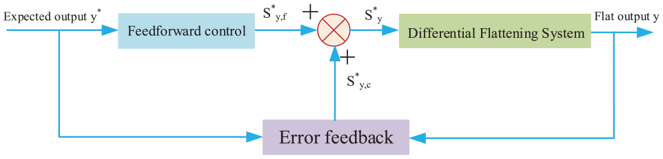
Block diagram of the DFBC system.
MPPT algorithm design for DFBC and APSO
Proof that single-phase PV MPPT are DFBC systems
According to the single-phase PV array MPPT control system structure (Figure 4), its system mathematical model can be obtained.
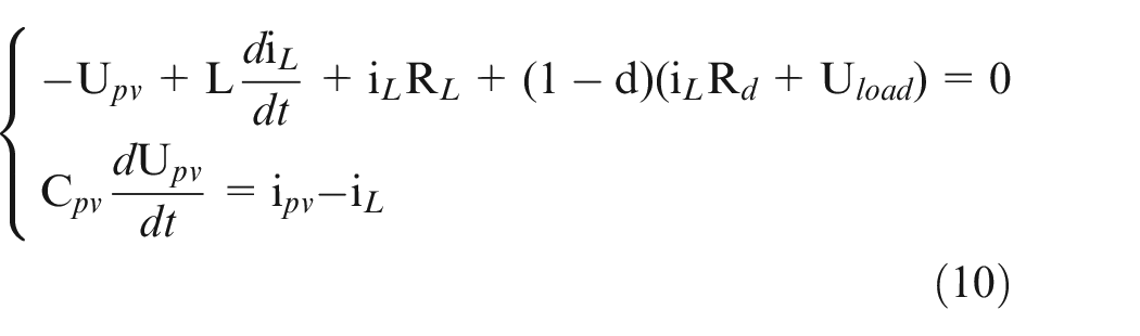
Where,
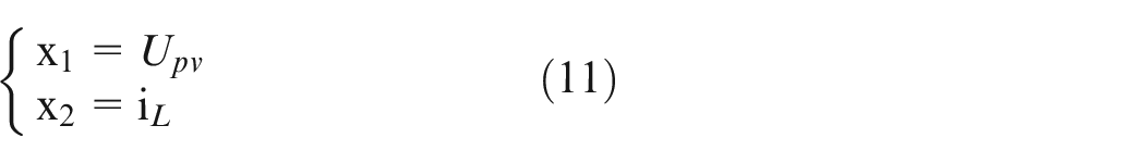
Select state variables:
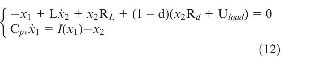
From equations (10) and (11), the equation of state of the system is obtained as:
The charge of the input capacitor
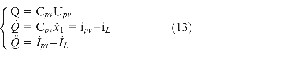
The charge Q of the capacitor
where
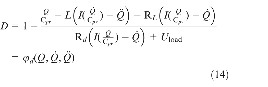
From the above derivation, the system shown in Figure 3 can be expressed in the form of equation (9), so the system is a differential flat system, and the duty cycle D of the boost circuit is chosen as the flat input quantity and the charge
Design of differential flat controller
The relationship between the duty cycle and the output and load voltages of the PV array can be obtained from the operating principle of the Boost circuit:
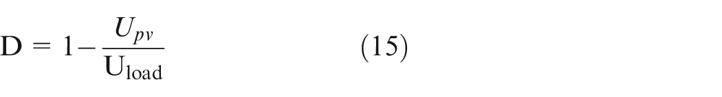
It can be seen that the MPPT problem of PV system is the relationship between duty cycle and output voltage of PV array and load voltage, and the control algorithm changes the output voltage of PV array by changing the duty cycle to achieve the purpose of MPPT.
The state variables and input variables of the differential flat control system can be uniquely determined by a set of flat outputs and their nth-order derivatives. Therefore, applying the differential flat control theory to the MPPT of PV system can realize the direct control of the PV array output voltage, which not only shortens the seeking time but also improves the robustness of the whole system.
Assuming that the output voltage of the desired PV system is the reference voltage
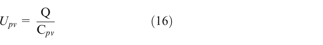
Therefore the setting of the flat output capacitance trajectory can be converted into the setting of the reference voltage trajectory, and finally the output voltage is tracked to the reference voltage.
To eliminate the steady-state error of the system, a second-order controller is used as an error feedback to correct for
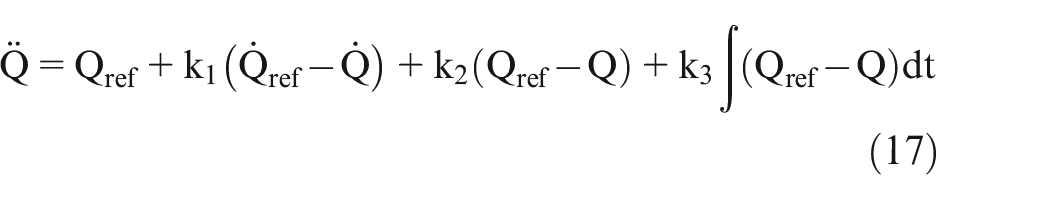
Figure 6 shows a block diagram of the reference voltage control to control the output voltage of the array.
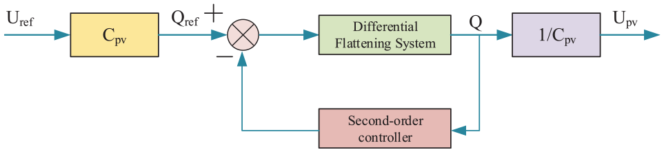
DFBC control array output voltage block diagram.
In summary, it can be seen that direct tracking of the output voltage of the PV array can be achieved using differential flattening control.
Design of MPPT for DFBC and APSO
In this paper, a combination of DFBC and APSO algorithm is used to implement MPPT control. The voltage of the PV array is selected as the location of the particle in the PSO algorithm to provide a reference voltage for the differential flat control of the PV array. The total output power of the PV array is used as an adaptation function with a particle population of 3 and a maximum number of 100 iterations. To cope with light intensity changes, the restart condition
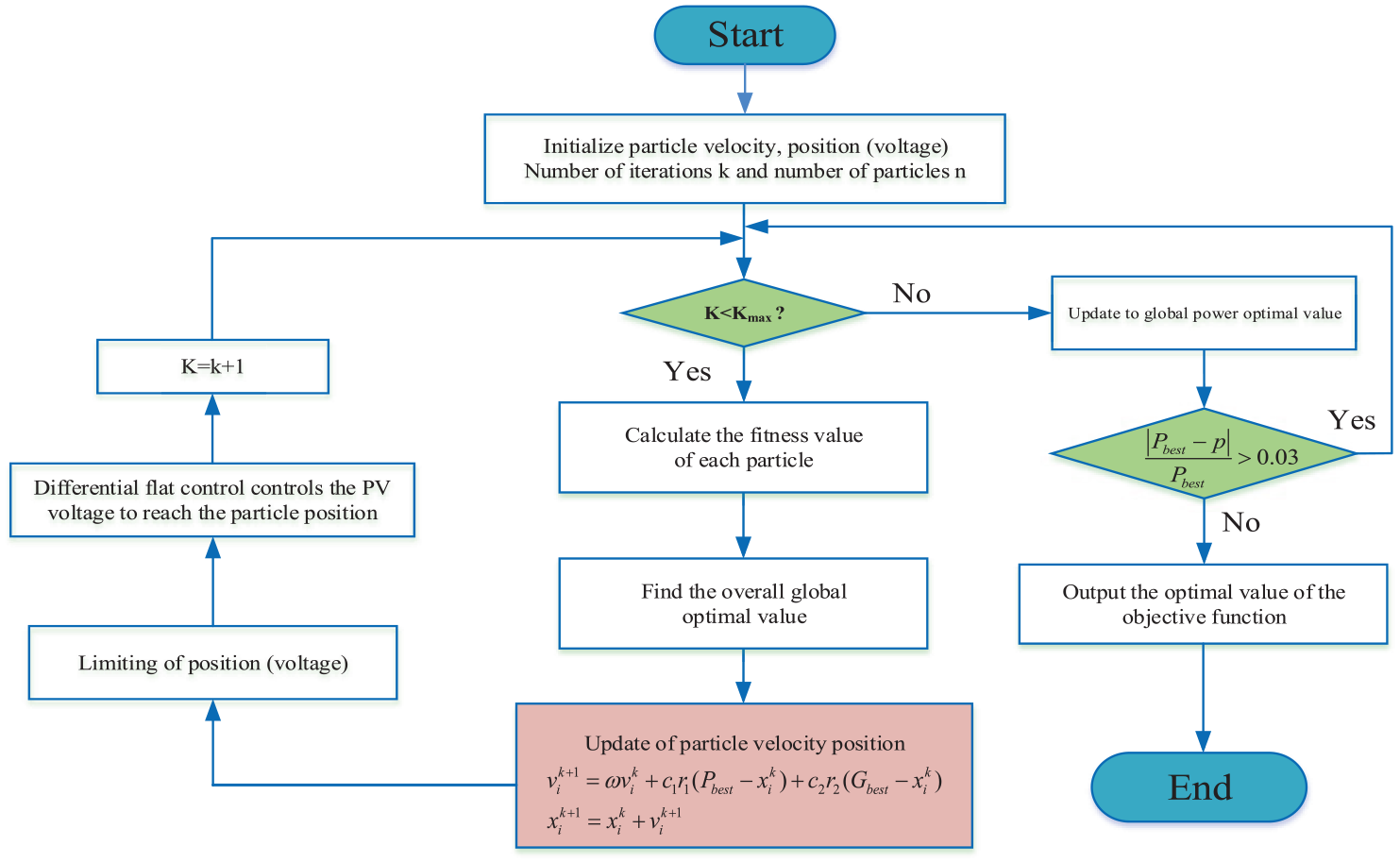
MPPT flow chart of DFBC and APSO.
Compared to the traditional PSO algorithm that changes the output voltage of the PV array by changing the duty cycle to achieve the MPPT purpose. A combination of DFBC and APSO algorithm is used to directly control the output voltage of the PV array for MPPT, which can shorten the seeking time and improve the robustness of the whole system. It ensures that all possible peak points are searched, and possible peak points are not lost, and at the same time, it can ensure that the algorithm will not fall into local extreme points, and finally obtain the global maximum power point.
Analysis of experimental results
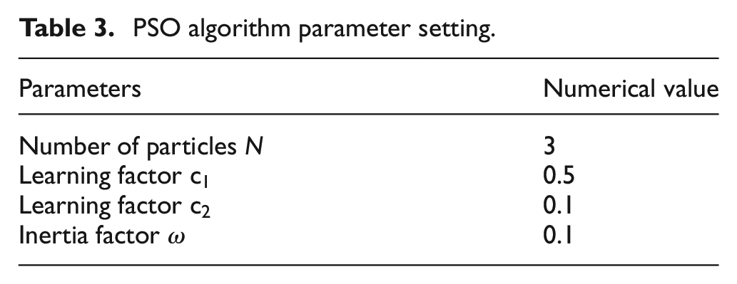
To verify the effectiveness of this control strategy, the simulation model is built in MATLAB2018a/SIMULINK as shown in Figure 4. The parameters of the simulated PV cells are shown in Table 1 and constitute the PV array as in Figure 2, and the light intensity is shown in Table 2. Different light intensities are provided according to the parameters in Table 2 to simulate the comparison of this control algorithm with the PSO algorithm under unshaded and shaded conditions. Among them, the important parameter settings of the traditional particle swarm algorithm are shown in Table 3.
PSO algorithm parameter setting.
Simulation without shade
The light intensity is provided for the battery cell according to Table 2 without shading. Simulations were performed with PSO, APSO, and DFBC and APSO control, respectively, and the P–t curves of the three tracking algorithms are shown in Figure 8, and the performance comparisons are shown in Table 4.
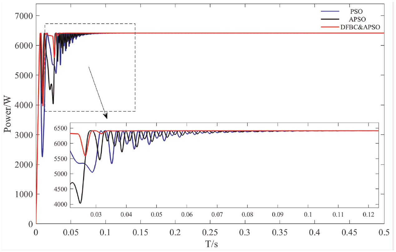
Power output curve without shade.
Comparison of performance without shade.
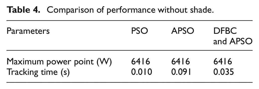
From the simulation results, it can be seen that the DFBC and APSO tracking time is significantly improved for tracking to the same maximum power point
Simulation with shade
Set the light intensity of the battery cell to provide light intensity according to Table 2 without shade mode before 2.5 s and according to Table 2 with shade mode after 2.5 s. Simulations were performed with PSO, APSO, and DFBC and APSO in the presence of shading, respectively. The P–t curves of the three algorithms are shown in Figure 9, and the performance comparisons are shown in Table 5.
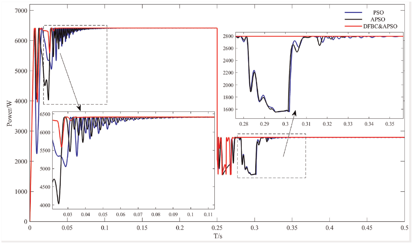
Power output curve with shaded.
Comparison of performance with shading.
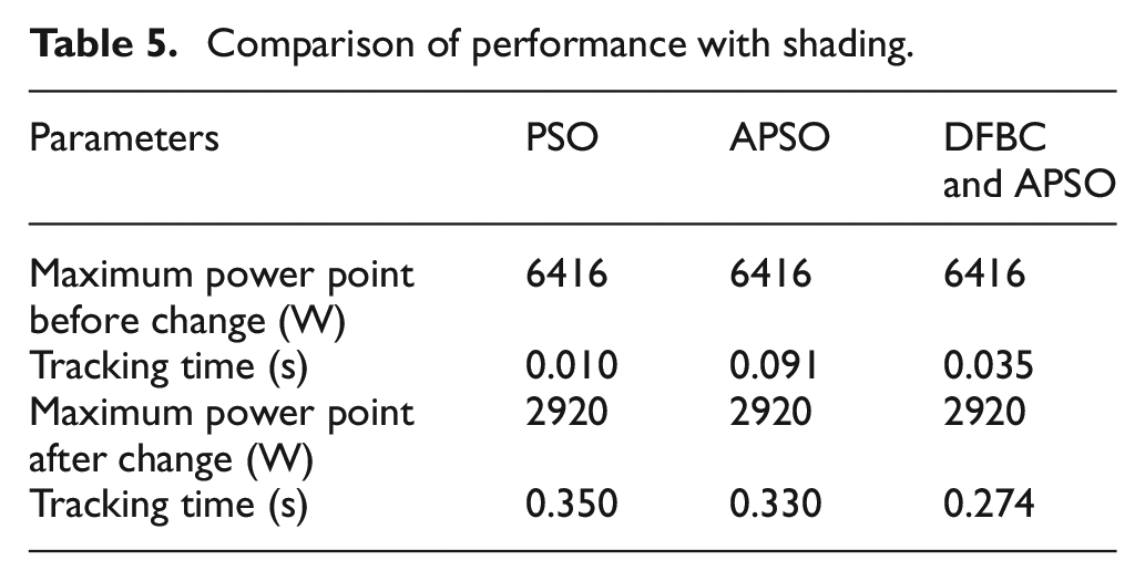
From the simulation results, it can be seen that the DFBC and APSO control algorithm used in this paper overcomes the problems of system oscillation caused by the PSO algorithm in the traditional sense of substantial random initialization of particle positions, and the existence of control lag misjudgment in the actual algorithm. Increasing the system response speed and the ability to quickly track to the maximum power in single-peak as well as multi-peak situations, increasing its convergence around the optimum.
Experimental verification
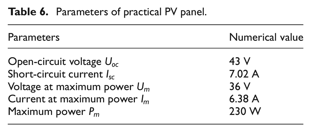
In order to prove the practical feasibility of the control strategy, the experimental platform of this paper is built by using Boost circuit, load, PV panel, and the main control chip is TMS320F28335. The actual PV board parameters are shown in Table 6, the physical object is shown in Figure 10.
Parameters of practical PV panel.
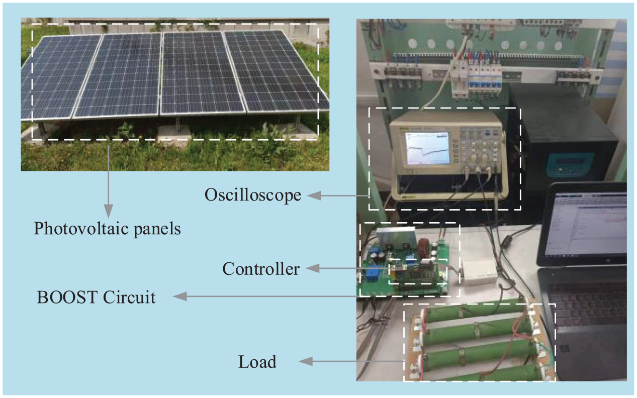
Photovoltaic hardware test platform.
The experiments were conducted by placing the 2 × 2 TCT structured PV arrays under outdoor sunlight and partially shading two of the series panels. By adjusting the value of the sliding resistor, the voltage and current values are collected by the A/D module, and the data is imported into Origin for data fitting curve, which roughly depicts the characteristic curve of the PV panel output, Figure 11 shows the PV panel output P–U fitting curve.
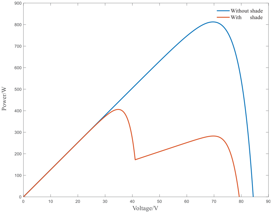
Photovoltaic cell output fitting curve.
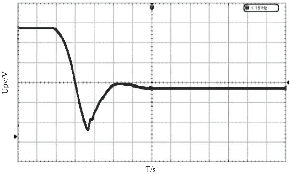
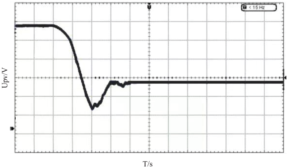
The output power of the PV panels is low because the light intensity and temperature in the test environment do not meet the requirements of the standard case. From Figure 11, it can be seen that the output characteristic curve of the volt cell shows a single peak when it is not shaded and two peaks when it is shaded, which is consistent with the output characteristic in the case of partial shadow shading. Therefore, experiments are conducted to verify the performance of the algorithm in the case of local shading. The experimental results are shown in Figures 12–14 by observing the output voltage waveform of the PV panel measured by the oscilloscope. The horizontal axis is time, and each grid is 0.5 s. the vertical axis is voltage, and each grid is 10 V. The collected data is imported into Origin through the A/D module for data fitting, and Figure 15 shows the output power curve by data fitting.
PSO control output voltage.
APSO control output voltage.
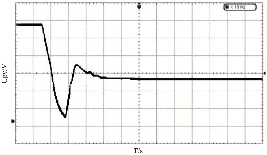
DFBC and APSO control output voltage.
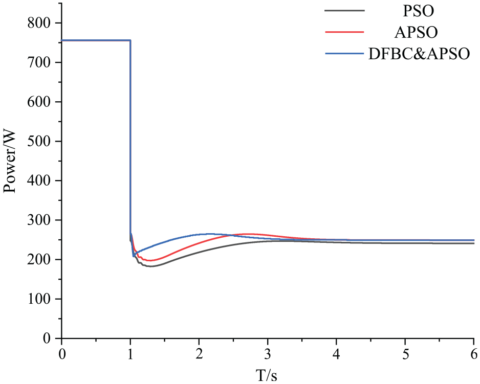
Experimental power fitting curve.
The results show that under partial shade conditions, the solar panels are re-stabilized to operate at the maximum power point under shade conditions with the control system. This control strategy can significantly improve the tracking accuracy and speed, which verifies the correctness of this control strategy in the maximum power point tracking control.
Conclusions
In this paper, DFBC and APSO is proposed for PV maximum power tracking control to perform MPPT by directly controlling the output voltage of PV arrays, which can both shorten the seeking time and improve the robustness of the whole system. It overcomes the problems that the traditional algorithm cannot track the global maximum point under shadow conditions, and has long tracking time, poor tracking accuracy and slow response time. Compared with the traditional particle swarm algorithm, the convergence speed of particle swarm is accelerated and the global search capability is improved. The MPPT method proposed in this paper has significant improvement in tracking time, tracking accuracy, and response speed compared with the traditional PSO algorithm, and finally achieves the purpose of improving the conversion efficiency of PV modules. Simulation and experimental results show that this control algorithm has excellent tracking effect even under the condition of drastic irradiance change, which can significantly improve the conversion efficiency of PV modules and increase the utilization rate of solar energy.
Footnotes
Declaration of conflicting interests
The author(s) declared no potential conflicts of interest with respect to the research, authorship, and/or publication of this article.
Funding
The author(s) disclosed receipt of the following financial support for the research, authorship, and/or publication of this article: This work was financially supported by the National Natural Science Foundation of China (Grant No. 61179012), the project of Department of Science and Technology of Jilin Province (Grant Nos. YDZJ202303CGZH001 and 20200404203YY).