
Abstract
When the converter transformer core is grounded at multi-points, a fault loop will be formed and a circulation will be generated, leading to local overheating of the magnetic core and decomposition of insulating oil. Therefore, the converter transformer core will be single point grounded. As a rare internal lead of converter transformer, the ground current on the core ground lead can often reflect the running state of converter transformer. In this paper, theoretical analysis, modeling simulation and experimental research are carried out on the ground current of converter transformer at one point. Firstly, according to the structure characteristics of converter transformer, the analytical modeling of ground current is carried out. Secondly, based on the structure characteristics of oil paper insulation, the equivalent capacitance of converter transformer is calculated. Then, the analytical and finite element simulation model of converter transformer is established, and the ground current of converter transformer is calculated. Finally, the correctness of the proposed scheme is verified by measuring the grounding current of converter transformer core.
Introduction
With the continuous progress of HVDC technology, DC transmission projects are developing rapidly all over the world.1–4 As one of the core components in the process of DC transmission, the state of converter transformer will directly affect the reliability of power grid.5–7
Compared with ordinary AC transformer, converter transformer will produce more harmonic and DC components due to the converter process, and then affect the grounding current. The multi-point grounding fault of the core causes the circulation between the ground point of the core, which will cause the overheating of transformer and burning of the core. 8 The core of the transformer in normal operation should be grounded at one point, but due to the design, manufacturing, transportation and installation, the core and clamping piece touch each other or touch the grounding part directly. 9 So, there is a circulation current in the core grounding wire during the operation of the transformer, and this situation often occurs in the substations. 10
Saleh et al. 11 present a performance comparison of the solid, low impedance, high impedance, frequency-selective, and isolated grounding systems. Aiming at transformer core earthing current monitoring, a non-contact current monitoring method based on a single monaxial tunneling magnetoresistance sensor is proposed. 12 As a VSC transformer whose structure and operating conditions are different from those of power transformer and converter transformer, its circuit simulation model is obtained by calculating the partial capacitance matrix, and the grounding current is calculated. 13 The grounding current of converter transformers in a ±500 and ±800 kV converter station were measured and corresponding harmonic characteristics were obtained. 14 Qinghao et al. 15 describe grounding wire of core becomes flexible, leads to the core produce suspended potential, results in discharge and causes transformer oil chromatographic analysis data anomalies. The research of transformer grounding current is mainly based on experiment and detection.16–19
As can be seen from the above, the current research on converter transformer core ground current is still mainly based on experimental testing, few technical means using finite element method simulation, lack of precise mathematical expression of converter transformer core ground current. On this basis, this paper carries on the mathematical modeling of the converter transformer core ground current, and considers the characteristics of the oil paper insulation structure, gives the mathematical expression of the converter transformer core ground current under normal (single point) grounding condition, and uses the PSCAD software for analysis and simulation. In addition, the simulation model of converter transformer core under normal grounding condition is established by MAGNET finite element software, and the simulation research is carried out. The correctness of the proposed scheme is verified by the simulation and experimental results.
Mathematical modeling of core grounding current of converter transformer
Basic parameters of converter transformer
In this paper, the analysis of single-phase double-winding converter transformer is taken as an example. In HVDC transmission projects, if single-phase double-winding converter transformer is used the converter station usually needs six converter transformers to realize the converter function. 20 The specific main connection mode is shown in Figure 1. The main structure of the single-phase double-winding converter transformer is shown in Figure 2.
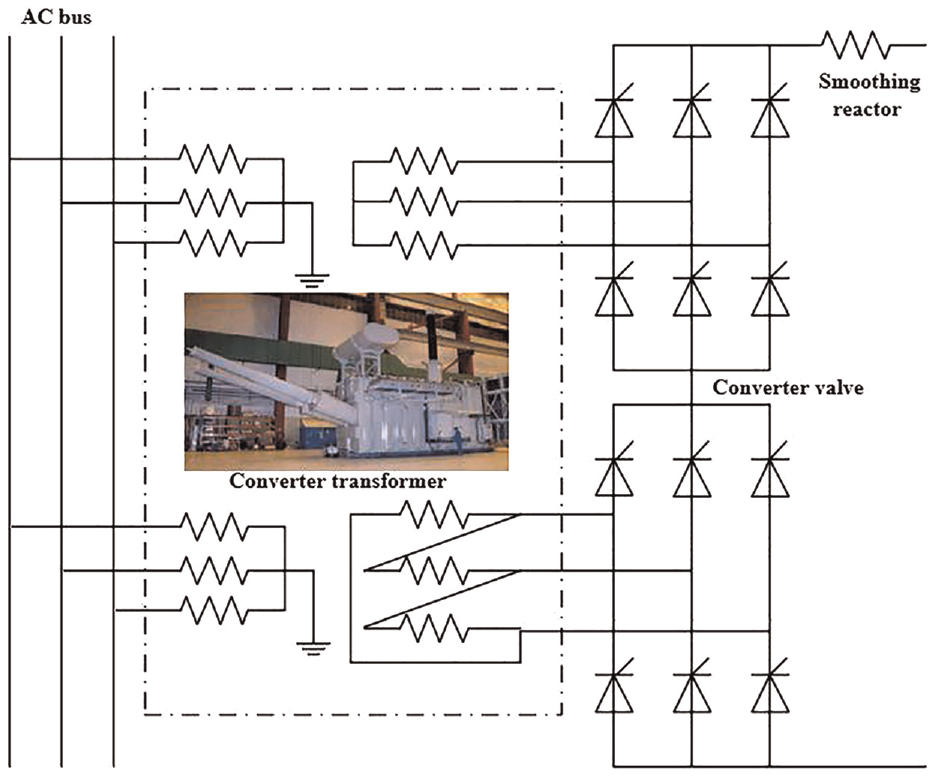
Converter transformer main connection mode.
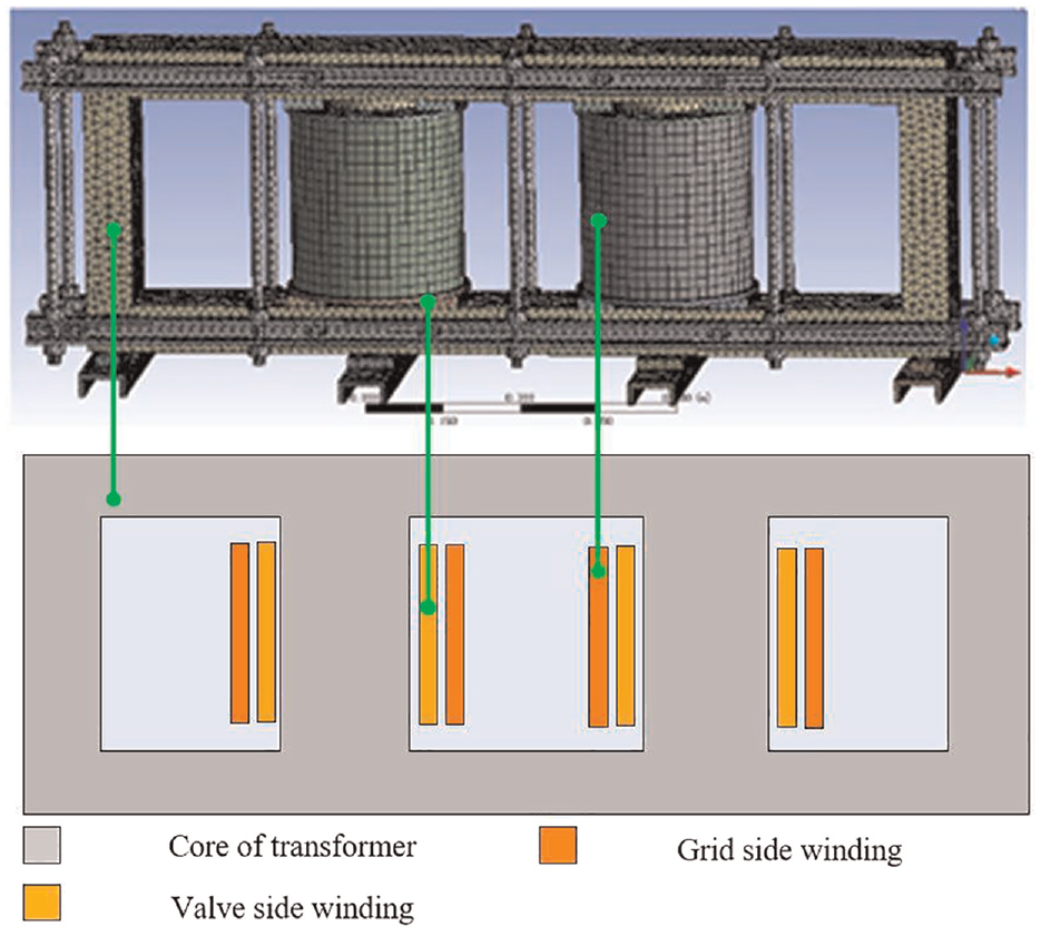
Converter transformer main structure.
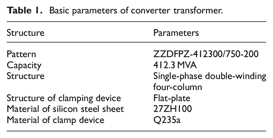
In Figure 2, the converter transformer adopts a single-phase double-winding four-column structure, and the windings are divided into grid-side windings and valve-side windings. The windings on each column are connected in parallel, wherein the grid-side winding is connected to the grid, and the valve-side winding and the voltage regulating winding are connected to the converter valve. The basic parameters of the single-phase double-winding converter transformer are shown in Table 1.
Basic parameters of converter transformer.
Analysis of grounding current mechanism of converter transformer
After long-term operation, the converter transformer may have problems such as insulation aging, insulation damage and winding discharge. When the converter transformer works in voltage fluctuation, DC bias, harmonics and other states, it will further aggravate the adverse consequences such as insulation aging, insulation damage and winding discharge.
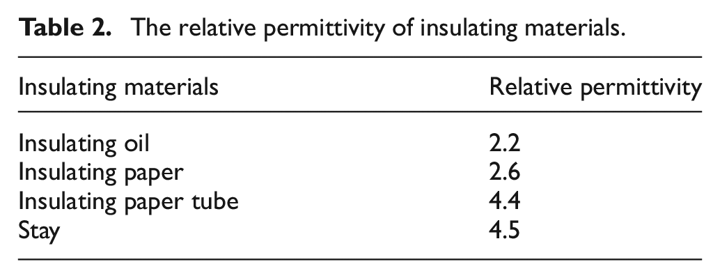
There is parasitic capacitance between high potential electrodes such as transformer coils and wires and low potential electrodes such as core and structural parts, which are mathematically analyzed below as an example of grounding currents of clamp. Table 2 shows the relative permittivity of insulating materials. When the converter transformer is operating, the grounding current I can be shown in (1).

where C is the distributed capacitance between two electrodes; U is the pressure difference between two electrodes; and ω is the angular frequency.
The relative permittivity of insulating materials.
A transformer core is a multilayer block stacked into a nearly cylindrical cylinder. Compared with the capacitive reactance between the core and the winding and other high potential conductors, the impedance of the insulating paint film on the surface of the core silicon steel sheet is very small and can be ignored. Single point grounding of transformer core is regarded as integral grounding. The flow path of ground current is shown in Figure 3 as “winding - parasitic capacitor - core - ground wire - ground.”
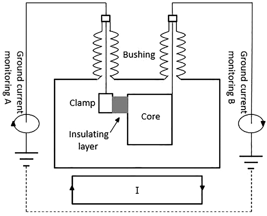
Grounding current flow path.
Therefore, the three main factors affecting ground current are as follows:
(1) Aging or damage of insulation changes the relative dielectric constant, enlarging the parasitic capacitance;
(2) Load changes, causing voltage fluctuations;
(3) The existence of higher harmonics makes the corresponding angular frequency higher
Calculation of distributed capacitance parameter of oil-paper insulation
The insulation in the converter transformer is generally composite insulation, rather than single medium insulation, insulation medium is mainly composed of insulating paper wrapped in a metal coil, transformer oil filled with an oil tank, and support the existence of oil strips and paper tubes. In this test, Alpha A broadband dielectric impedance spectrometer from NOVOCONTROL, Germany, was used to measure insulation materials. The experimental device is shown in Figure 4.
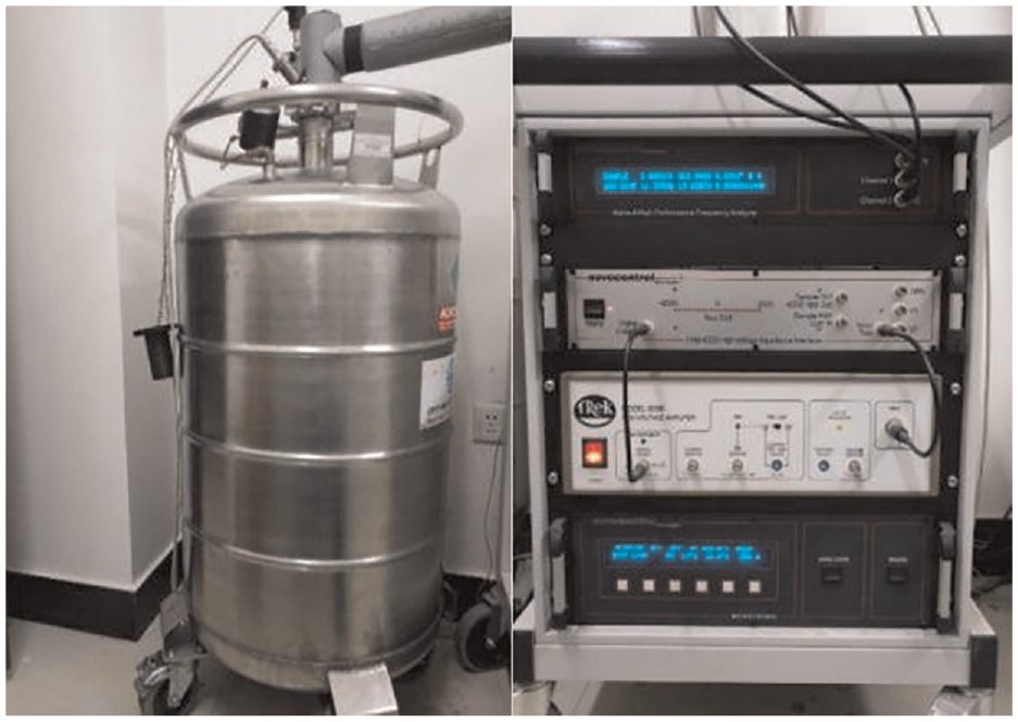
Relative permittivity test platform.
The relative permittivity of each insulating material in the transformer is shown in Table 1. The accuracy of calculating the equivalent dielectric constant of composite insulating materials is the basis of calculating capacitance parameters. Figure 5 shows relative permittivity spectrum of insulating oil in frequency domain.
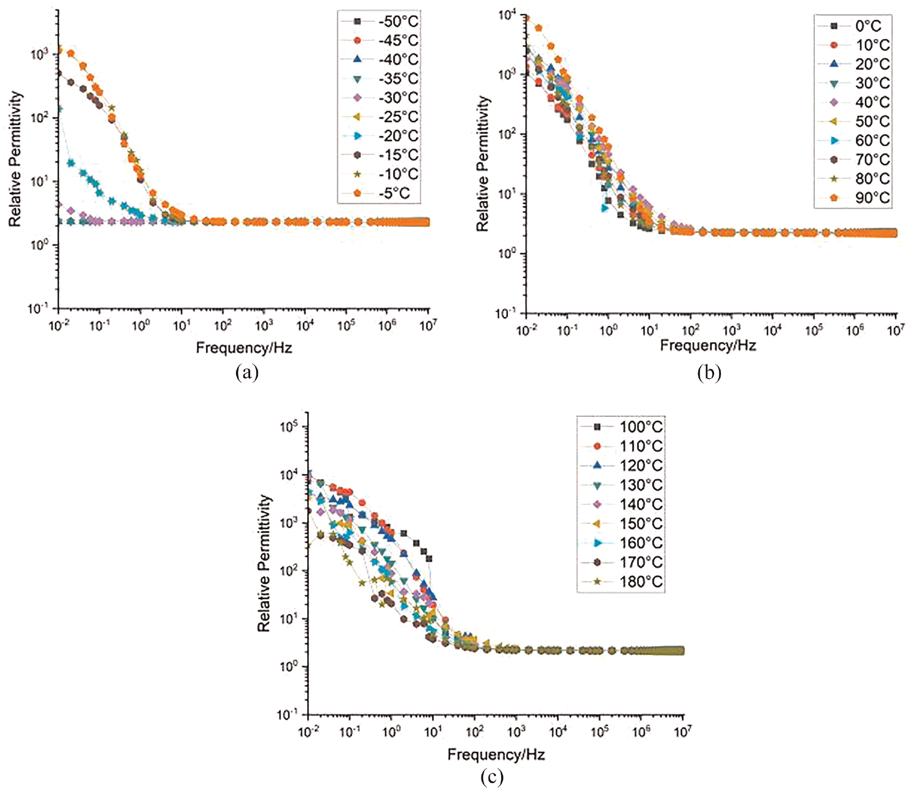
Relative permittivity spectrum of insulating oil in frequency domain: (a) −50°C−5°C, (b) 0°C−90°C, and (c)100°C−180°C.
The composite insulation between windings consists of an insulating paper tube, oil channel (pure oil channel or with braces), inner or outer turn insulating paper, and other media, and its insulation structure is shown in Figure 6. The insulating medium between the windings can be regarded as composed of insulating paper outside the valve windings, oil channel, insulating paper tube, and insulating paper inside the net windings in series. The oil channel part is compound insulation, which is composed of a parallel connection between the struts and transformer oil. Equivalent insulation between windings is shown in Figure 7.
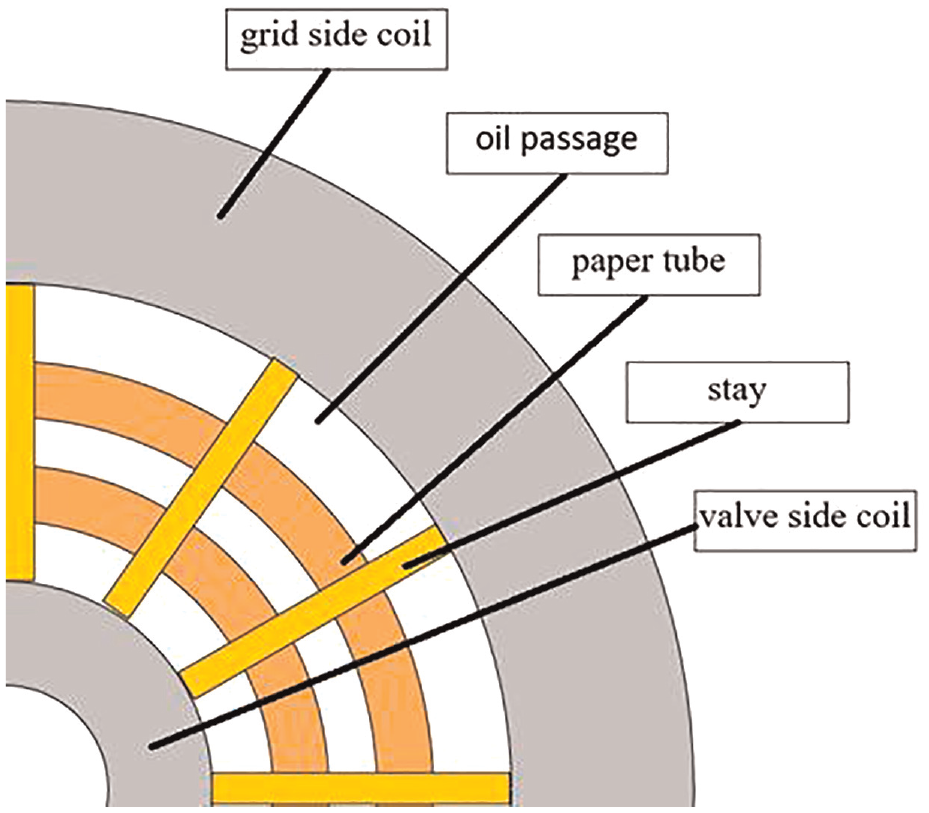
The insulation structure.
Schematic diagram of equivalent insulation.
When the converter transformer uses oil-paper insulation, the equivalent dielectric constant of the composite insulation has to be calculated before performing the capacitance calculation. According to the series-parallel relation of the insulating medium shown in Figure 6, the equivalent relative permittivity can be obtained by (2).
where,
Among them, the relative dielectric constant of oil passage and brace can be calculated according to (3):
where
By substituting the actual structure size of the converter transformer into (4), the equivalent dielectric constant of the insulating medium between windings on the left side of the converter transformer can be obtained.
The geometric capacitance of the winding to the core shield can be calculated according to the concentric cylindrical capacitor formula:
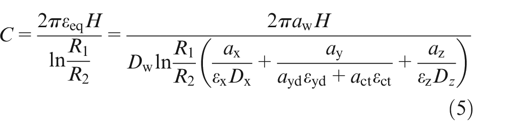
where
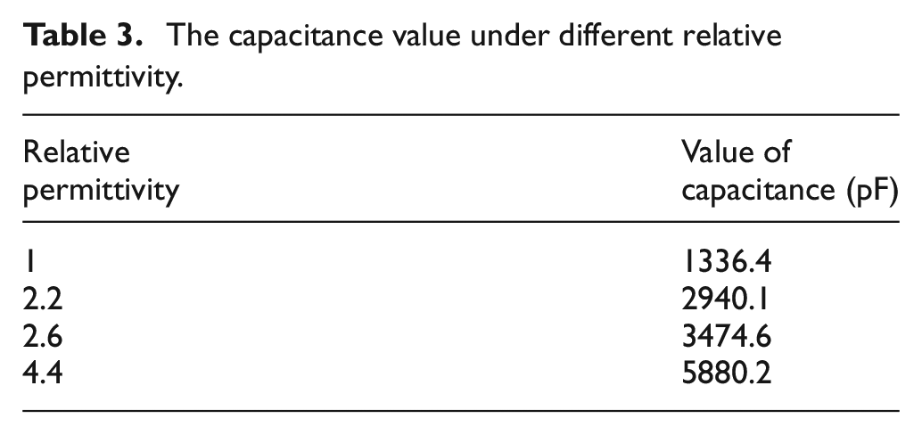
Different relative permittivity will directly affect the value of capacitance. Figure 8 shows the calculation simulation model of capacitance under different relative permittivity, and Table 3 shows the capacitance value under different relative permittivity.
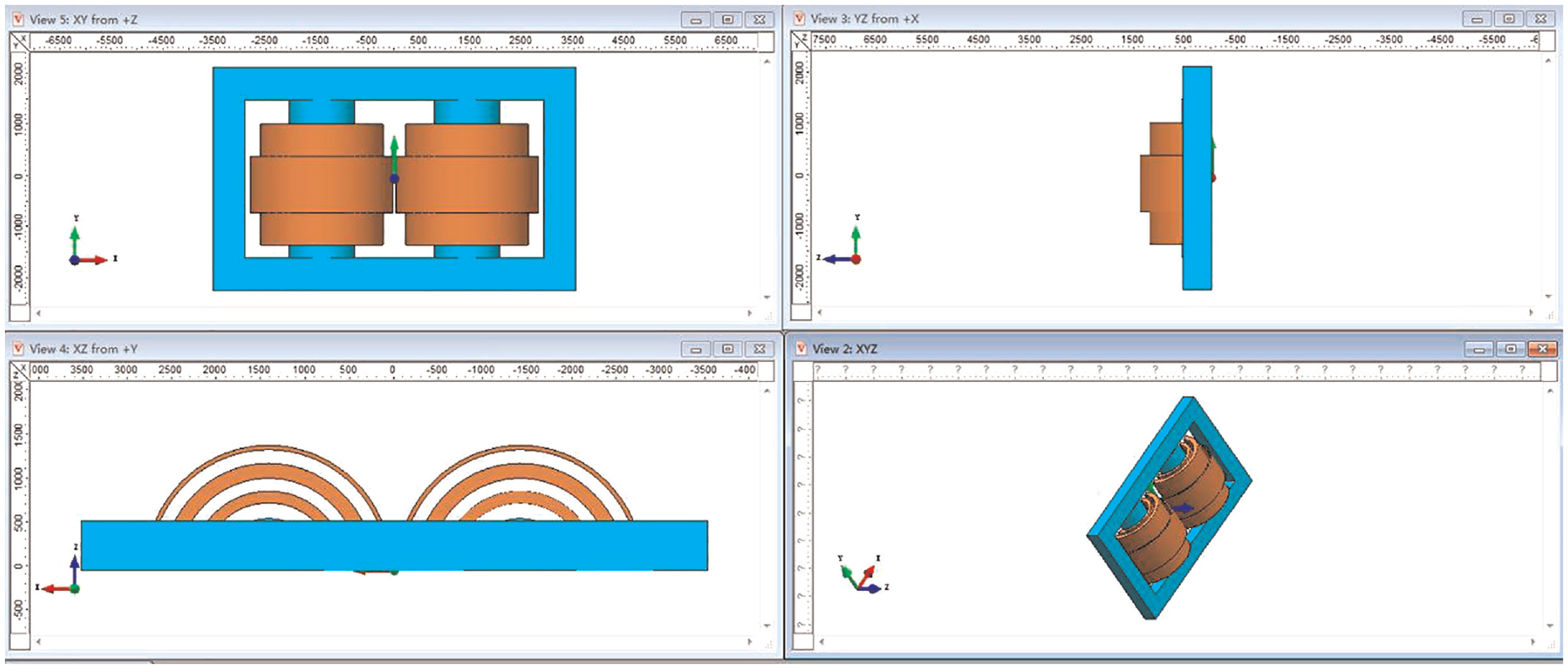
Calculation model of capacitance under different relative permittivity.
The capacitance value under different relative permittivity.
Calculation of grounding current of converter transformer core
Under the condition of rated frequency, the voltage distribution of the converter transformer winding can be arranged according to the equivalent inductance of the winding, so the distributed voltage of the winding can be expressed as:
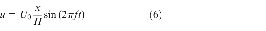
where,
By integrating from the bottom of the wind along the height direction, the grounding current of the single point grounding of the converter transformer core can be obtained as:
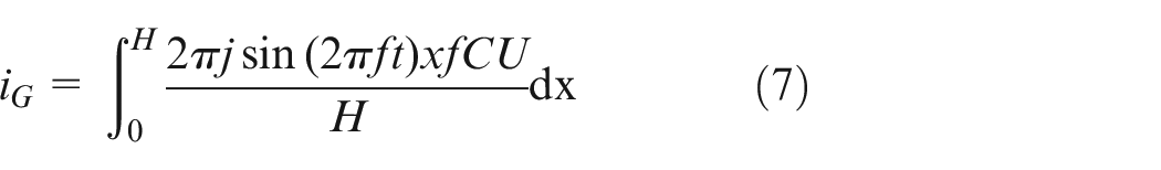
Based on the above equation, a simulation model is established in PSCAD to calculate and analyze the grounding current of the converter transformer core.
As shown in (11), the grounding current is affected by the relative dielectric constant of the capacitor, the input voltage of the transformer, and the geometry of the winding.
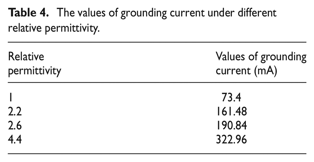
Table 4 shows the values of grounding current under different relative permittivity.
The values of grounding current under different relative permittivity.
Simulation and analysis of core grounding current of converter transformer
Analytical simulation and analysis of ground current of converter transformer core
According to the above, the calculation model of single-point ground current of converter transformer core is established. Figure 9 shows the simulation model of high voltage transmission. Figure 10 shows the ground current comparison of the single-point grounding of the converter transformer under different loads. Table 5 shows the core grounding current value of analytical method.
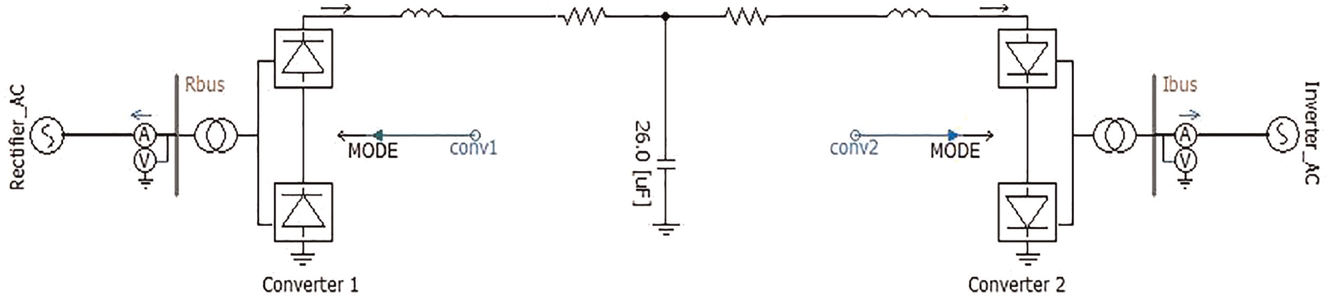
HVDC transmission simulation modeling.

Waveform single point grounding current of converter transformer under different loads: (a) current at 70% load, (b) current at 80% load, (c) current at 90% load, and (d) current at 100% load.
The core grounding current of analytical method.

Finite element simulation and analysis of ground current of converter transformer core
For the finite element calculation of the core single point ground current, in addition to the steps of general finite element modeling, it is necessary to set the anisotropic conductivity of the converter transformer core. Figure 11 shows the magnetic density distribution and excitation current waveform of the converter transformer under no-load conditions.
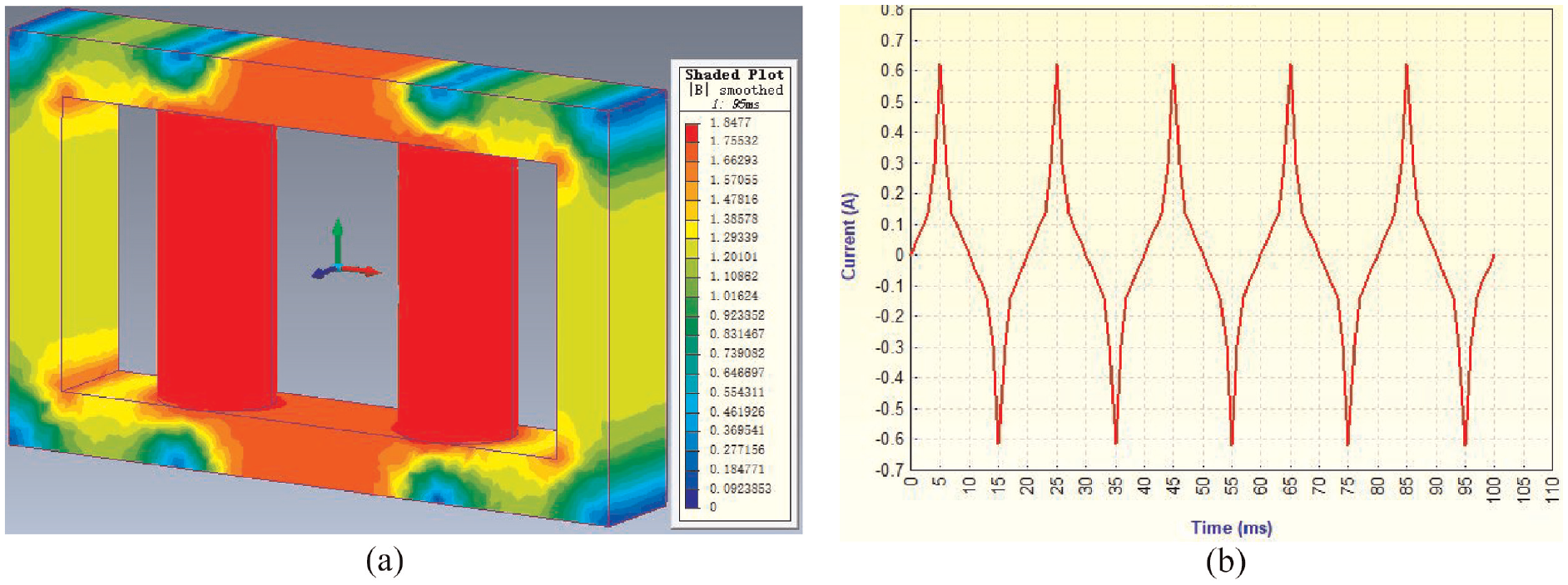
Magnetic density distribution and excitation current waveform of converter transformer under the no-load condition: (a) magnetic density distribution of converter transformer and (b) excitation current waveform.
As can be seen from Figure 11, the average magnetic density of the converter transformer core is 1.8 T, and the effective value of excitation current is 0.43 A, which verifies the correctness of the finite element method in modeling, subdivision, materials, and other aspects.
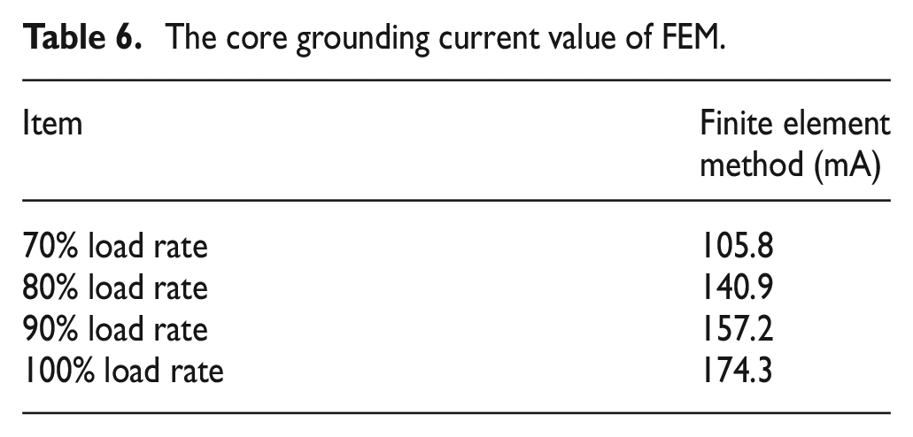
Figure 12 shows the converter transformer current density when the converter transformer at different load rate, and Table 6 shows the core grounding current when the converter transformer at different load rate.
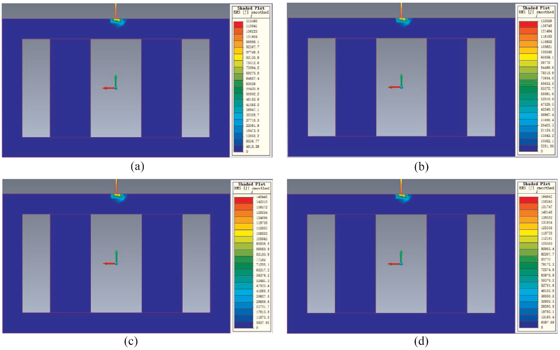
The current density of the converter transformer: (a) 70% load, (b) 80% load, (c) 90% load, and (d) 100% load.
The core grounding current value of FEM.
Experiment and analysis of grounding current of converter transformer core
Carry out experimental research on the grounding current of the converter transformer core. Figure 10 shows the ground point and test point of the converter transformer core; Figure 13 shows the grounding current experiment of the converter transformer core carried out by the clamp ammeter used in this paper. Table 7 shows the comparison of grounding current of converter transformer core by analytical method, finite element method, and experimental method.
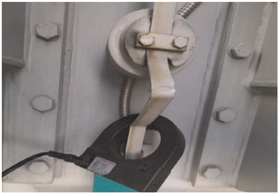
Converter transformer grounding wire.
Comparison of grounding current of the converter transformer core.
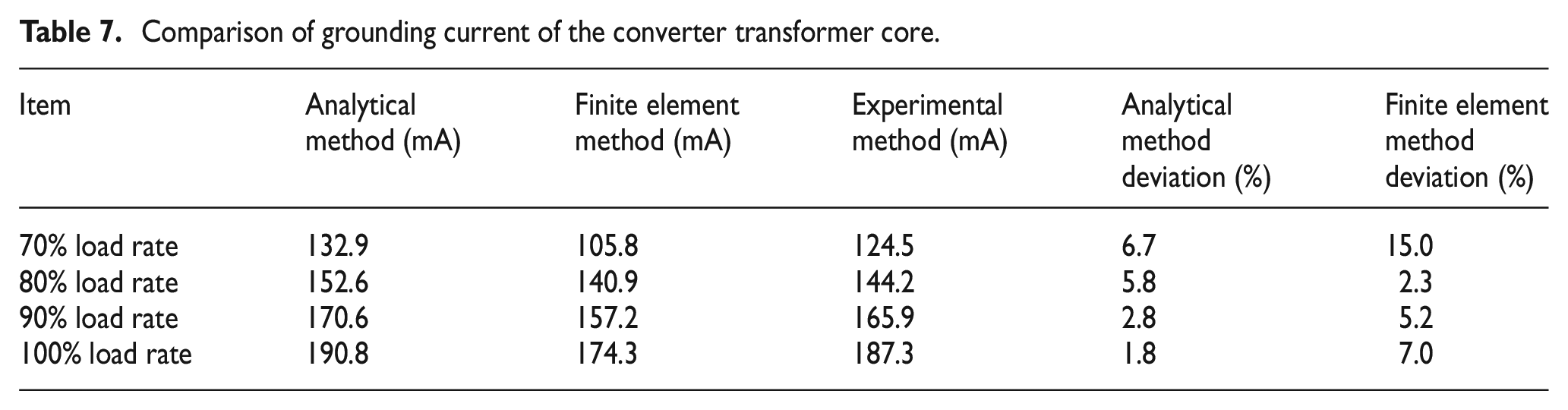
It can be seen from Table 6 that the analytical method has a deviation of 6.7% at a load rate of 70% and a deviation of 1.8% at a load rate of 100%, which meets the engineering requirements. The deviation of the finite element method is 15% at 70% load rate, and the deviation is 7% at 100% load rate. There is no significant change in the deviation, and the maximum deviation value is 15%.
Conclusion
The grounding current of converter transformer core is calculated and studied in this paper.
(1) The analytical calculation formula of converter transformer core ground current based on equivalent dielectric constant is established. On this basis, the converter transformer core ground current under different load rates is calculated. The research results show that the higher the load rate, the larger the converter transformer core ground current, the smaller the calculation deviation (calculation deviation within 10%, meet the engineering requirements).
(2) The grounding current is affected by the relative dielectric constant of the capacitor, the input voltage of the transformer, and the geometry of the winding.
(3) The experimental research on the grounding current of converter transformer core is experimentally studied, and compared with the analytical method and finite element method, the correctness of the proposed scheme is verified.
Footnotes
Declaration of conflicting interests
The author(s) declared no potential conflicts of interest with respect to the research, authorship, and/or publication of this article.
Funding
The author(s) disclosed receipt of the following financial support for the research, authorship, and/or publication of this article: This research was funded by The Key Research and Development Program of Ningxia Hui Autonomous Region (2021BDE931018); Science and Technology Project of State Grid Ningxia Electric Power Co., LTD. (5229DK20004N).