
Abstract
Measurement principle of axis straightness error of cylindrical parts was introduced based on their roundness profiles. The evaluation models of the center coordinates of four kinds of the reference circles were built, and the evaluation models of the axis straightness errors were established by using the least-square and minimum zone criteria. The roundness profiles of eight simulated cylinders, eight holes, and eight shafts were extracted, and their axis straightness errors were evaluated based on the different reference circles and evaluation criteria. The “minimax” issues in the evaluation process of axis straightness errors were be solved by using Equilibrium Optimizer, and its implementation flows were given. Their evaluation results were analyzed under the used reference circles and evaluation criteria. The analysis results showed that both reference circles and evaluation criteria have much influence on the evaluation results, and that among the evaluation results based on the centers’ coordinates of four reference circles and two evaluation criteria, the axis straightness errors evaluated based on the center coordinates of least-square reference circle and the minimum zone criteria is the least one for most of cylindrical parts, the roundness profiles of which may have no singularities, and the differences among the axis straightness errors evaluated on the basis of different reference circles and different evaluation criteria are very large sometimes, which should be noted in checking whether the axis straightness errors of parts are qualified.
Keywords
Introduction
Axis straightness tolerance is one of form tolerances of cylindrical parts, which is often indicated in the drawing of holes and shafts according to the independent principle and the relative principle, such as envelope principle, 1 maximum material requirement, and least material requirement. 2 Therefore, the axis straightness error is an important index characterizing the features of cylindrical parts, which may have much influence on the fit feature of hole and shaft. The axis straightness errors of parts are often measured based on the roundness profile extraction strategy 3 on the cylindricity measuring instrument and evaluated according to the center coordinates of the reference circles of the extracted roundness profiles. The axis straightness errors can be evaluated by using the least-square criterion and minimum zone criterion,4,5 and the center coordinates of the reference circle of the roundness profiles can be determined according to the least-square criterion, minimum circumscribed criterion, maximum inscribed criterion and minimum zone criterion, the corresponding reference circles of which are the least-square circle, the minimum circumscribed circle, the maximum inscribed circle, and the minimum zone circle.6–10 According to the definition of axis straightness error, its evaluation should comply with the minimum zone criterion, but it is also often evaluated by the least-square criterion, which is called approximate evaluation method. With the rapid development of intelligent manufacturing, the evaluation method of the geometric errors of parts needs to be clearly indicated on the drawing, that is, the geometric error will be tested according to the indicated evaluation method, and there is no problem of so-called approximate evaluation method. Therefore, ISO/TC 213 provides some additional symbols in ISO 1101 11 for the drawing indications of the geometrical tolerances. In the same way, it is necessary to give a definite evaluation method in the drawing indications of axial straightness tolerances. In order to make the designer choose the proper evaluation method of the axis error according to the need of the part function, it is necessary to study the influences of different reference circles on axis straightness error, so as to indicate the corresponding additional symbol of the geometric tolerance on the drawing, These influences were researched according to the evaluation results of some simulated cylindrical features’ profiles and parts in this paper, and may be taken as the references in the evaluation indications of axis straightness tolerances in the drawings by the designers.
Measurement principle of axis straightness error of cylindrical parts
The axis straightness error can be measured by using the cylindricity measuring instrument, Talyrond 585LT of which is shown in Figure 1.The cylindrical part is placed on the rotary table of the instrument, and after the part is centered and leveled, its roundness profiles can be extracted according to the parameters, such as sampling point number n of a roundness profile, the number m of roundness profiles of the measured part, the distance Δz between two adjacent roundness profiles, the filter type and the number of undulations per revolution(UPR). The coordinates of the jth sampling point in the ith roundness profile of the measured cylindrical part in the coordinate system of the cylindricity measuring instrument are ρij, φij, and zi, where ρij is the sum of the radial variation of the jth sampling point in the ith roundness profile measured by the inductance sensor and a value measured by the grating distance sensor of the radial measuring arm assembly in Figure 1, φij is the angle between the jth sampling point in the ith roundness profile and x axis, which can be calculated as follows,

where Δφ is equal to 2π/n. The meanings of ρij and φij can also be seen in Figure 2, where the ith roundness profile is shown.
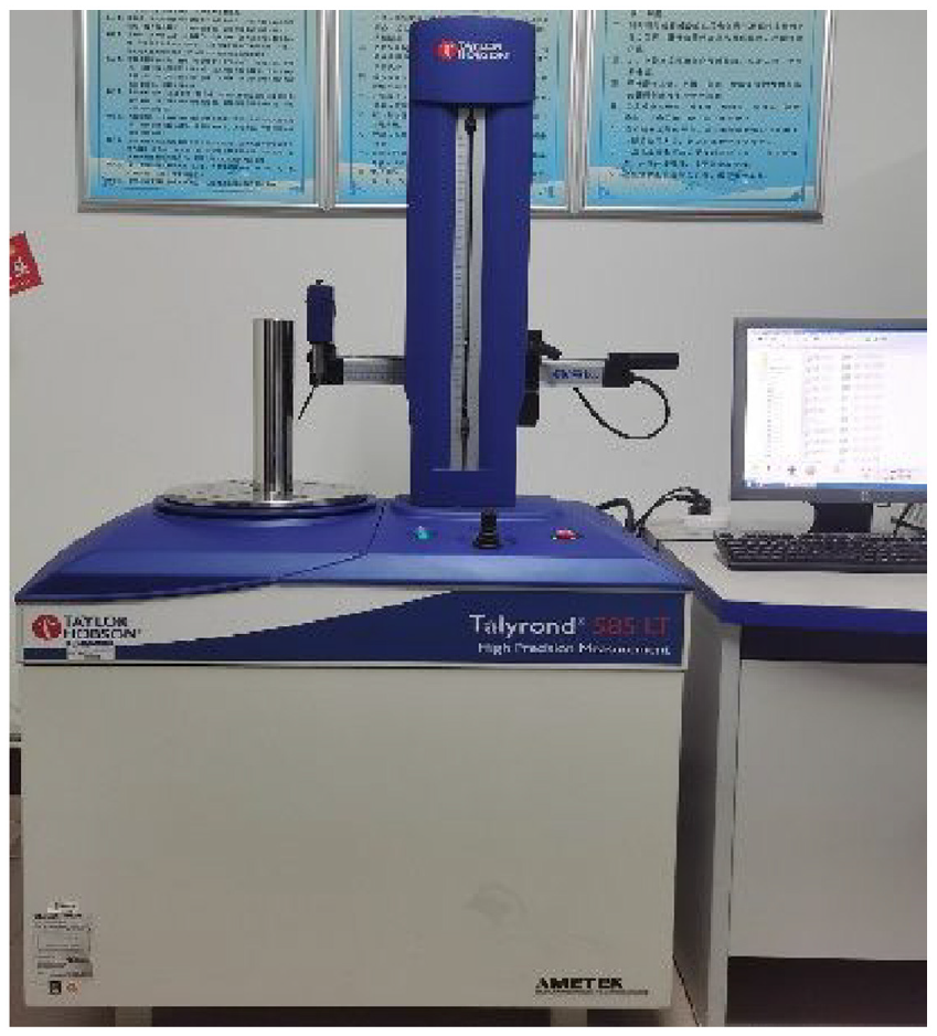
Talyrond 585LT cylindricity measuring instrument.
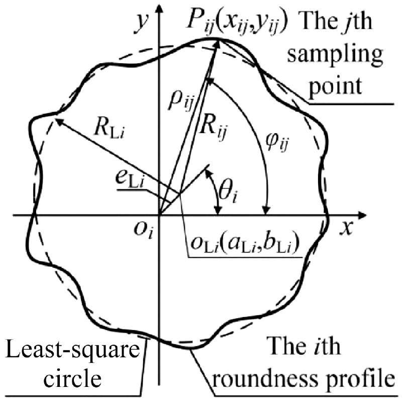
ρij and φij of the ith roundness profile.
Evaluation models of axis straightness errors
The extracted profiles of the cylindrical part are shown in Figure 3, where zi is the vertical distance between the ith roundness profile and xoy plane, which is equal to (i–1)Δz. According to the extracted profiles, we can determine the corresponding center coordinates oXi(aXi, bXi) of their reference circles, where the subscript X can be replaced by one of L, C, I, and Z, which correspond to the centers of the least-square circle(LSC), the minimum circumscribed circle (MCC), the maximum inscribed circle(MIC), and the minimum zone circle(MZC), respectively, as shown in Figure 4.
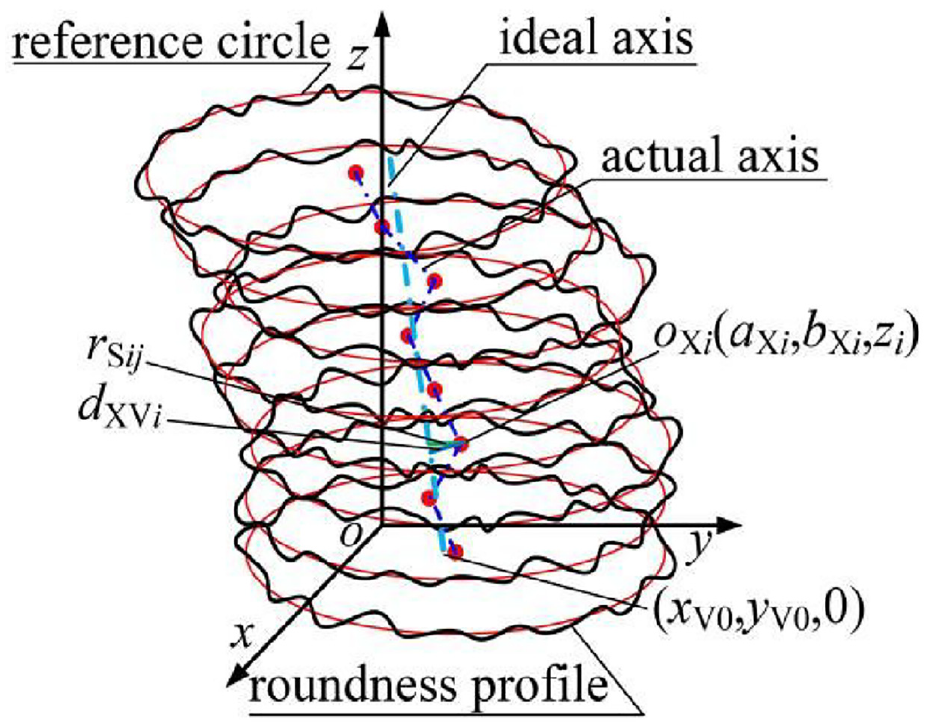
Schematic of actual axis and the ideal axis of the reference cylinder.
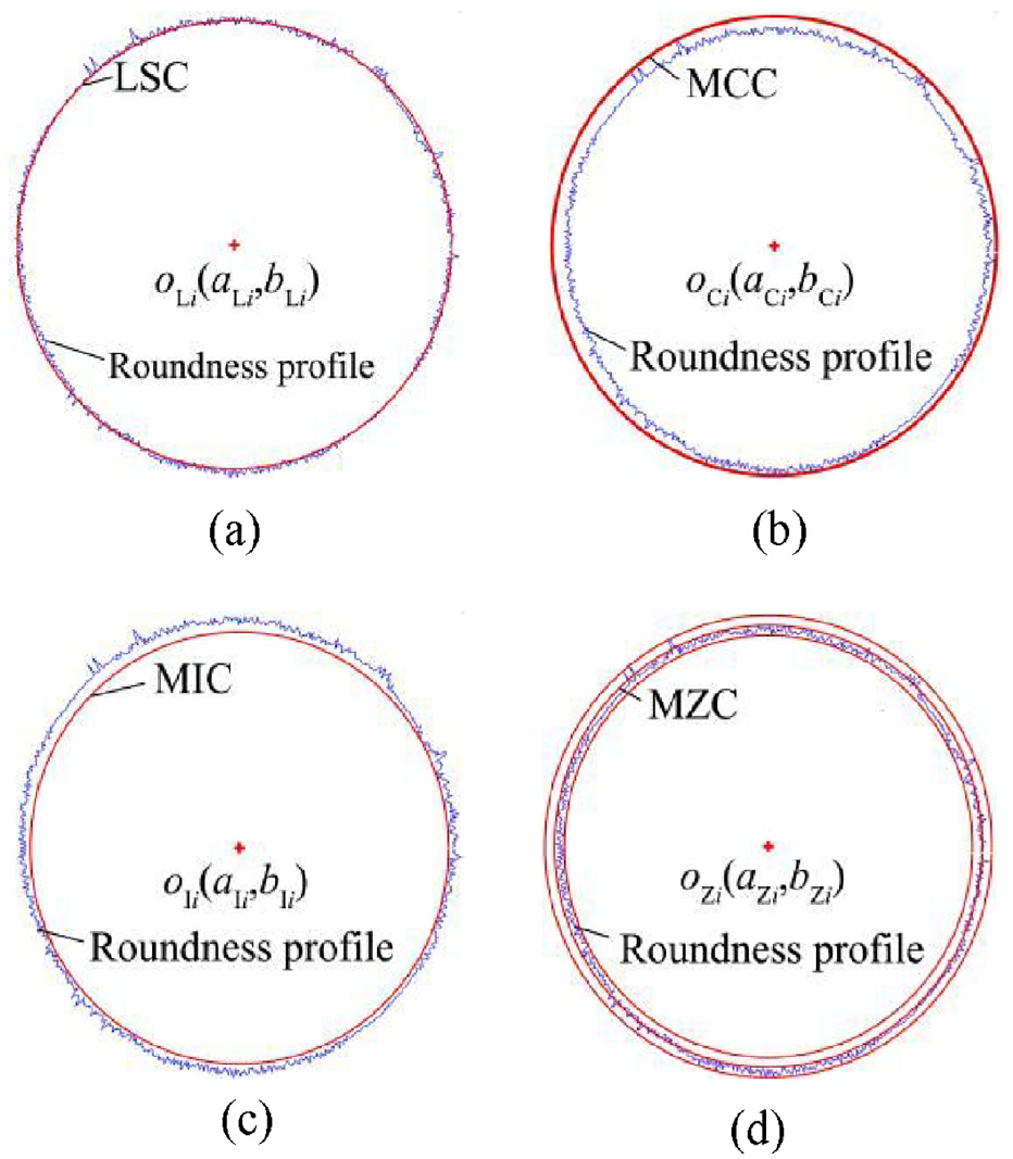
Schematic of reference circles and their centers’ coordinates: (a) LSC, (b) MCC, (c) MIC, and (d) MZC.
According to the definition of the least-square method, LSC and its center coordinates can be expressed as follows,
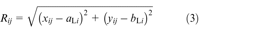
where RLi is LSC’s radius of the ith roundness profile, and Rij is the distance between the jth sampling point in the ith roundness profile and the LSC’s center oLi of the ith roundness profile in the xoiy plane, as shown in Figure 2. Rij can be calculated by the following equation.
where the meanings of
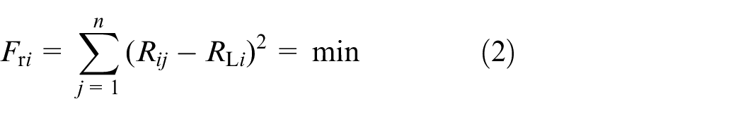
From equation (3), it is known that equation (2) is a non-linear least-square issue, and Parameters
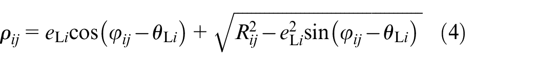
After centering and levelling of the measured cylindrical part on the rotary table, the eccentricity eLi between the center oLi of LSC and the rotary axis of the rotary table may be small enough, and

Rij in equation (5) is substituted for equation (2), and the nonlinear least-square issue is changed into a linear least-square one. We can calculate the partial derivatives of Fri in equation (2) for the undetermined parameters aLi, bLi, and RLi and make them equal to zero respectively, that is,
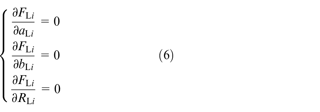
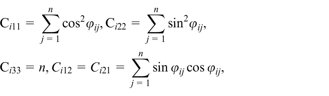
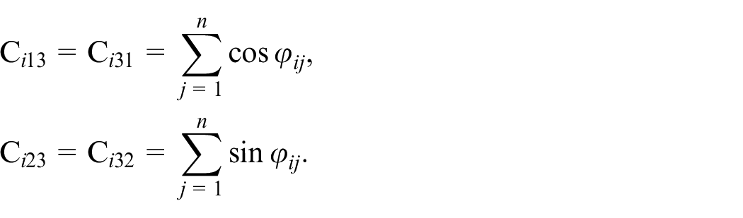
Further collating equation (6), the equations of the first degree of three variables are obtained as follows,
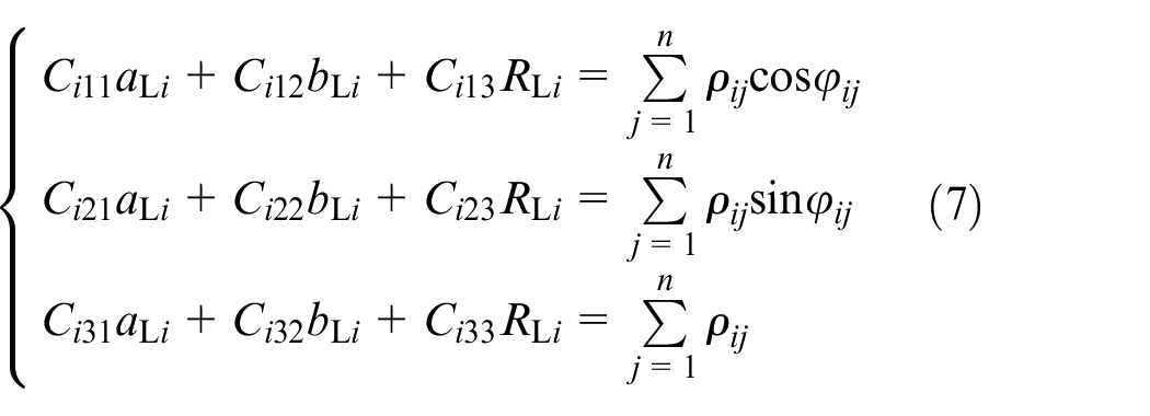
where
The undetermined parameter aLi, bLi, and RLi, of LSC of the ith roundness profile can be obtained by solving equation (7).
The x and y coordinates of center of other three reference circles can be determined according to the following optimization objective functions.
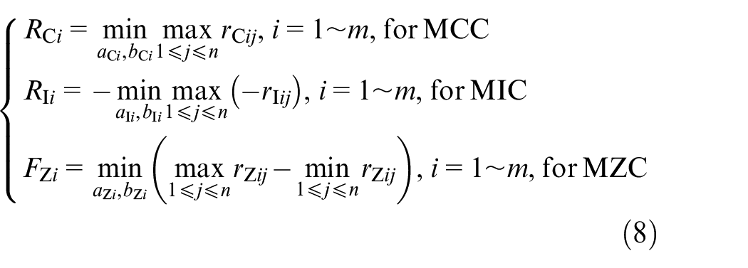
where RCi, RIi, and FZi are the radius of MCC, the radius of MIC and the roundness error of the ith roundness profile evaluated based on the minimum zone criterion, respectively, rCij, rIij, and rZij are the distance from the jth sampling point in the ith roundness profile to the center oCi of MCC, the center oIi of MIC and the center oZi of MZC, respectively, which can be calculated as follows,
From equation (8), searching the center oCi of MCC, the center oIi of MIC and the center oZi of MZC of the ith roundness profile is actually an optimization issue. Some researchers have studied many optimization algorithms12–14 for three corresponding evaluation criteria of the roundness.
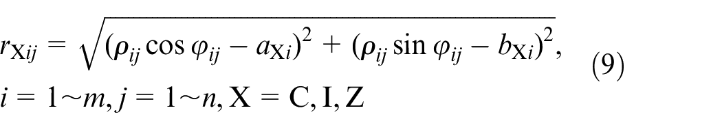
For the evaluation of axis straightness error of cylindrical part, we can build an axis formula with six parameters, such as the coordinates x0, y0, and z0 of one end of the axis, the angels α, β, and γ between the axis and the x, y, and z axes in the xoyz coordinate system. Owing to that the end of the axis is in the xoy plane and cos2α + cos2β + cos2γ = 1, so z0 = 0 and the axis can be expressed by four parameters, such as x0, y0, p, and q, where p = cosα/cosγ and q = cosβ/cosγ. The vertical distance from the center oXi of the ith reference circle to the axis can be calculated as follows, 15
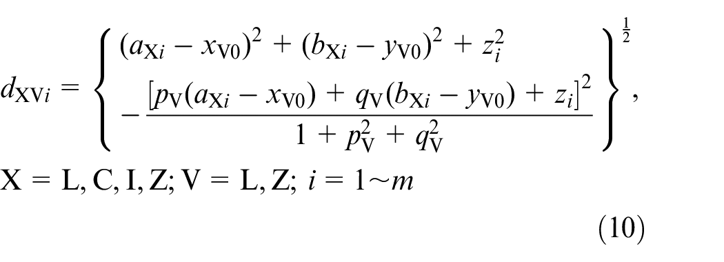
where xV0, yV0, pV, qV are four parameters of the axis evaluated based on the least-square criterion or the minimum zone criterion, which is represented by Symbol L or Z, aXi, bXi, and zi are the three coordinates of the center oXi of one of four reference circles of the ith roundness profile.
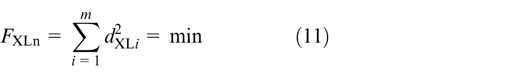
According to the definition of axis straightness error and the least-square criterion, four parameters of the axis and the corresponding radius of the least-square cylinder should satisfy the following condition, that is,
From equations (10) and (11), we can know that equation (11) is a nonlinear formula. If we hope to obtain four parameters of the axis above, we should use the optimization algorithm to solute the nonlinear issue. For simplification, if the absolute values of four parameters of the axis are smaller enough, the nonlinear issue in equation (11) can be changed into a linear one, which can be expressed as follows,
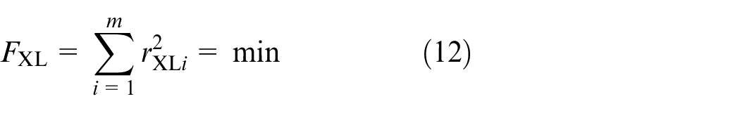
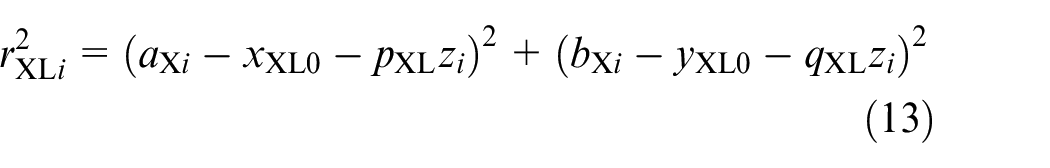
where rXLi is the radial distance from the center oXi of the ith reference circle to the axis, which can be calculated by equation (13).
We can take the partial derivatives of FXL in equation (12) on xXL0, pXL, yXL0, and qXL and make those partial derivatives equal to zero, respectively, and the quaternion system of first order equations can be obtained as follows,
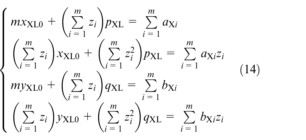
We can obtain the axis parameters xXL0, yXL0, pXL, and qXL of the least-square cylinder of the cylindrical axis straightness error through solution of equation (14). The axis straightness error evaluated based on the least-square criterion can be expressed as follows,
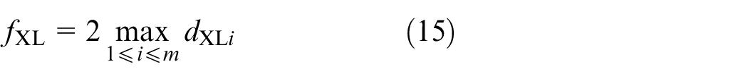
According to the definition of the minimum zone criterion, we can evaluate the axis straightness error as follows,
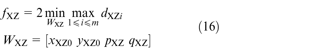
From equation (16), we can know that the evaluation of axis straightness error based on the minimum zone criterion is also an optimization issue, which can be solved by using the optimization algorithms.16,17
In this paper, the “minimax” issues in equations (8) and (16) were be solved by using Equilibrium optimizer (EO). EO is a novel optimization algorithm inspired by control volume mass balance models used to estimate both dynamic and equilibrium states, which was first proposed by Afshin Faramarzi, Mohammad Heidarinejad, Brent Stephens, and Seyedali Mirjalili in 2020. The detail about the theory, the related parameters and equations of EO can be seen in Reference. 18 The implementation flows of EO are as follows,
Step 1: Input Particle population size N, Maximum iterations M_iter and Initial concentration CX0 = WX0 for searching the center coordinates of MCC, MIC, and MZC, and CX0 = WX0 for searching the minimum zone axis parameters, respectively.
Step 2: Input Sampling points n and the distance ρij, j = 1∼n, in equations (5) and (7) of the ith roundness profile for the center coordinates of the reference circles. Input the parameter judge, which may be 1, 2, and 3 corresponding to MCC, MIC, and MZC, respectively. For searching the minimum zone axis parameters, input the roundness profiles’ number m of a cylinder and the center coordinates of the reference circle of the roundness profiles of a cylinder. Input searching boundary coefficient bc.
Step 3: Set the searching lower and upper boundaries lb and ub in two sides of CX0, lb = CX0–bc×|CX0|, ub = CX0 + bc×|CX0|. Set the free parameters a1 = 2, a2 = 1, GP = 0.5. Suppose that Ceq is the concentration candidate, which is a 2D and 4D row vector for the reference circles and the minimum zone axis parameters, respectively. Initialize Ceq1 = Ceq2 = Ceq3 = Ceq4 = [0 0] and Ceq1 = Ceq2 = Ceq3 = Ceq4 = [0 0 0 0] for 2D and 4D row vectors, respectively, and set their corresponding fitness values Ceq1_fit = Ceq2_fit = Ceq3_fit = Ceq4_fit = ∞. Let iter = 0.
Step 4: Randomly generate the lth CXl, l = 1∼N, in the range of lb and ub; Calculate N + 1 fitness values FV for CXl, l = 0∼N, by using equations (8) and (9) for the center coordinates of the reference circles, and by using equations (16) and (10) for the minimum zone axis parameters; Select the best fitness value FVmin from N + 1 fitness values, and the global best variables CXmin correspond to FVmin.
Step 5: Judge whether or not CXl, l = 1∼N, is beyond the searching boundary. If CXl>ub, set CXl = ub; if CXl>lb, set CXl = lb. Calculate N fitness values FV l for CXl, l = 1∼N, by using equations (8) and (9) for the center coordinates of the reference circles, and by using equations (16) and (10) for the minimum zone axis parameters; Select the best fitness value FVmin and CXmin correspond to FVmin. If FV l < FVmin, FVmin = FV l , CXmin = CXl, l = 1∼N.
Step 6: Set Ceq1, Ceq2, Ceq3, Ceq4, Ceq1_fit, Ceq2_fit, Ceq3_fit and Ceq4_fit again. If FV l < Ceq1_fit, Ceq1_fit = FV l , Ceq1 = CXl. If Ceq1_fit < FV l < Ceq2_fit, Ceq2_fit = FV l , Ceq2 = CXl. If Ceq1_fit < FV l , and Ceq2_fit < FV l <Ceq3_fit, Ceq3_fit = FV l , Ceq3 = CXl. If Ceq1_fit < FV l , Ceq2_fit < FV l , and Ceq3_fit < FV l <Ceq4_fit, Ceq4_fit= FV l , Ceq4 = CXl.
Step 7: Judge whether or not iter is equal to zero. If iter = 0, FV_old = FV, and CX_old = CX. If FV l _old < FV l , FV l = FV l _old, and CXl = CXl_old. FV_old = FV, and CX_old = CX.
Step 8: Calculate averaged candidate of Ceqk, k = 1–4, that is, Ceq_ave= (Ceq1 + Ceq2+Ceq3 + Ceq4)/4, and equilibrium pool: C_pool = [Ceq1; Ceq2; Ceq3; Ceq4]. Let t = (1-Iter/Max_iter)^(a2×Iter/Max_iter).
Step 9: Let
Step10: Let F = a1*sign(r–0.5).*(exp(−λ. *t)−1), r1 and r2 are equal to a single uniformly distributed random number in the interval (0,1), respectively, GCP = 0.5 × r1 × ones(1,dim)×(r2 ≥ GP), where ones(1,dim) is a dim dimensional(2D or 3D) unit row vector. Let G0 = GCP. *(Ceq-λ.*CXl), G = G0.*F, CXl = Ceq+(CXl-Ceq).*F+(G./λ*V). *(1 - F).
Step 11: Let Iter = Iter+1. if Iter<Max_iter, return to Step 5, otherwise, the best searching result of the concentration candidate WXB = CXmin.
In the flows’ formulas above, Symbol.* means multiplication of its front and back vectors.
For searching the center coordinates of MCC, MIC, and MZC, and the minimum zone axis parameters, N, M_iter, bc are set as 20, 200, 40, respectively. The LSC’s center coordinates WLi = [aLibLi], i = 1∼m, is set as WX0, X = C, I, Z, for MCC, MIC and MZC of the ith roundness profile; The least-square axis parameters WXL = [xXL0yXL0pXLqXL], X=L, C, I, Z, is set as WX0. According to the implementation flows of EO above, the EO subprograms for the “minimax” issues in equations (8) and (16) were developed.
Experiment and discussion
Experiment
For the research of influence of different reference circles on the evaluation results of axis straightness errors of cylindrical part, the roundness profiles of a series of cylindrical parts were simulated and their corresponding center coordinates of the relative reference circles were obtained based on the least-square criterion, the minimum circumscribed criterion, the maximum inscribed criterion, and the minimum zone criterion, respectively. According to the center coordinates of cylindrical parts, the axis straightness errors of cylindrical parts were evaluated by using equations (15) and (16), respectively, and the four parameters of the axis obtained by using equation (15) can be used as the initial optimization parameters of the axis in equation (16). The simulated profiles of the eight cylinders(c-1∼c-8) are shown in Figure 5, the local magnification of which is 1000. The simulated extraction method of profiles of cylinder can be seen in Zhao et al. 19
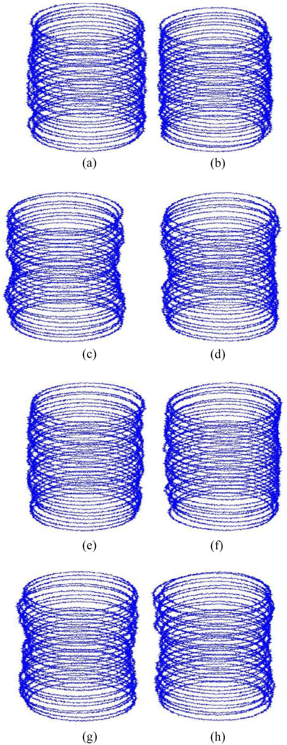
Simulated profiles of the eight cylindrical parts: (a) c-1, (b) c-2, (c) c-3, (d) c-4, (e) c-5, (f) c-6, (g) c-7, and (h) c-8.
Based on the x and y coordinates oXi(aXi, bXi), i = 1∼m, of the roundness profiles of the cylinders shown in Figure 5 by using equation (7). we can obtain the least-square axis parameters xXL0, yXL0, pXL, and qXL based on equation (14), where the subscript i is from 1 to m, and m and n are 20 and 1000, respectively.
According to the obtained least-square axis parameters xXL0, yXL0, pXL, and qXL of eight cylinders, we can gain their least-square axis straightness errors fXL based on equations (10) and (15), which are shown in Figure 6(a). The minimum zone axis parameters xXZ0, yXZ0, pXZ, and qXZ are searched by using EO subprogram, where the least-square axis parameters are their initial parameters. Based on the minimum zone axis parameters xXZ0, yXZ0, pXZ and qXZ of eight cylindrical parts and equations (10) and (16), the minimum zone axis straightness errors fXZ can be obtained, as shown in Figure 6(a). The fXV/fLL and fXZ/ fXL values of eight cylinders are shown in Figure 6(b) and (c), respectively.
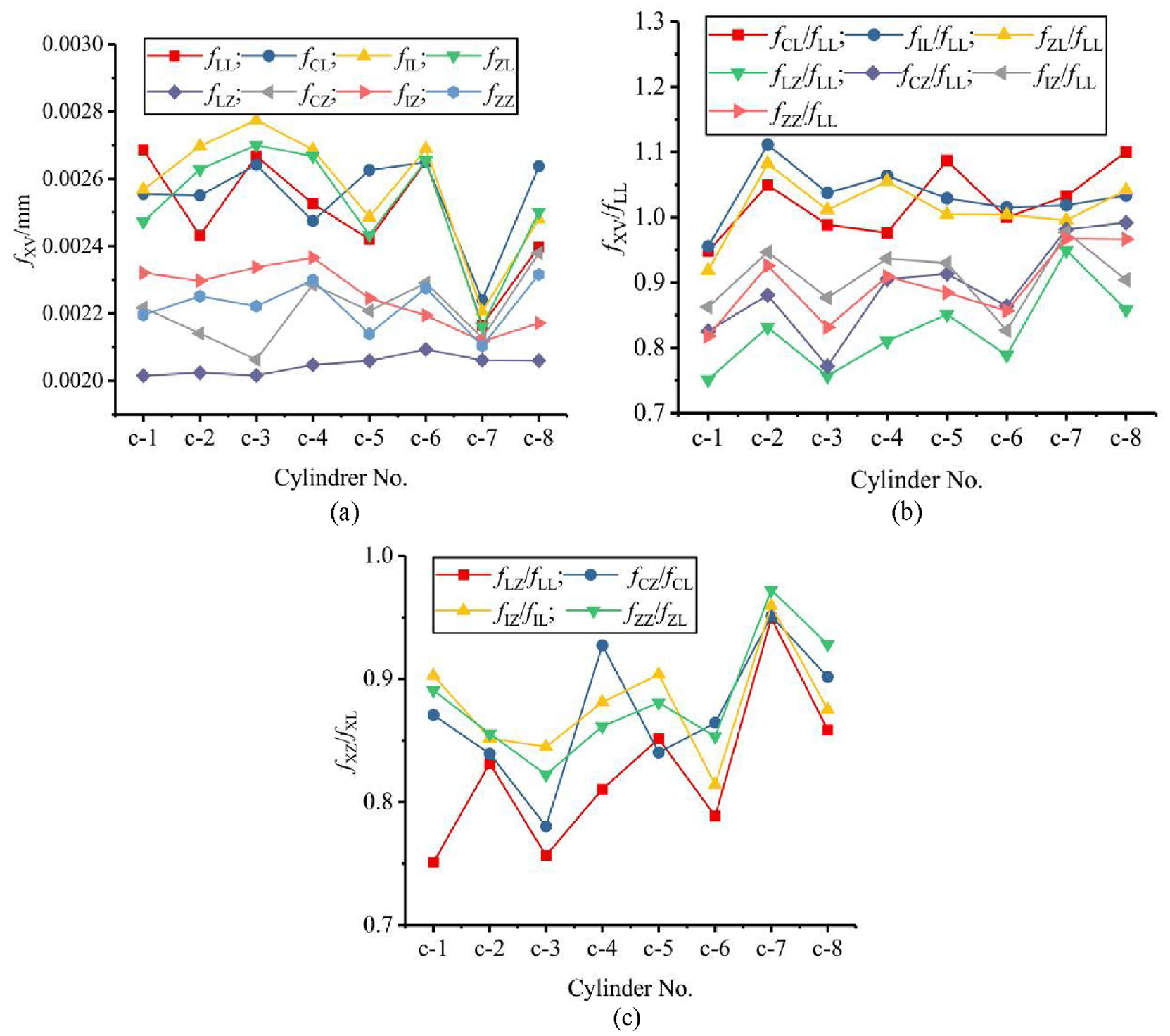
Evaluation results of axis straightness errors of eight simulated cylinders in Figure 5: (a) fXV, (b) fXV/fLL, and (c) fXZ/fXL.
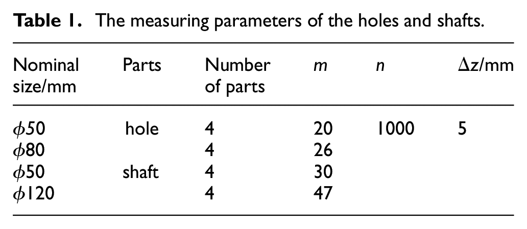
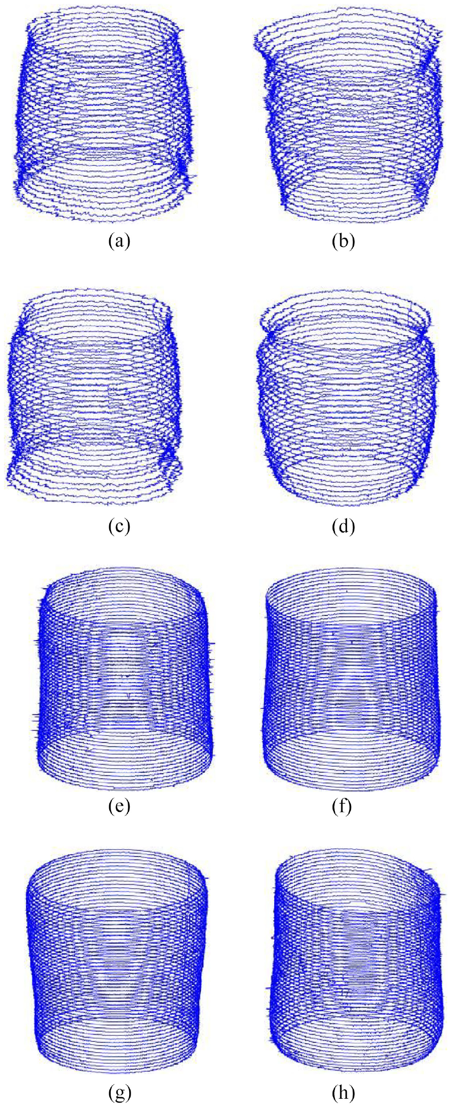
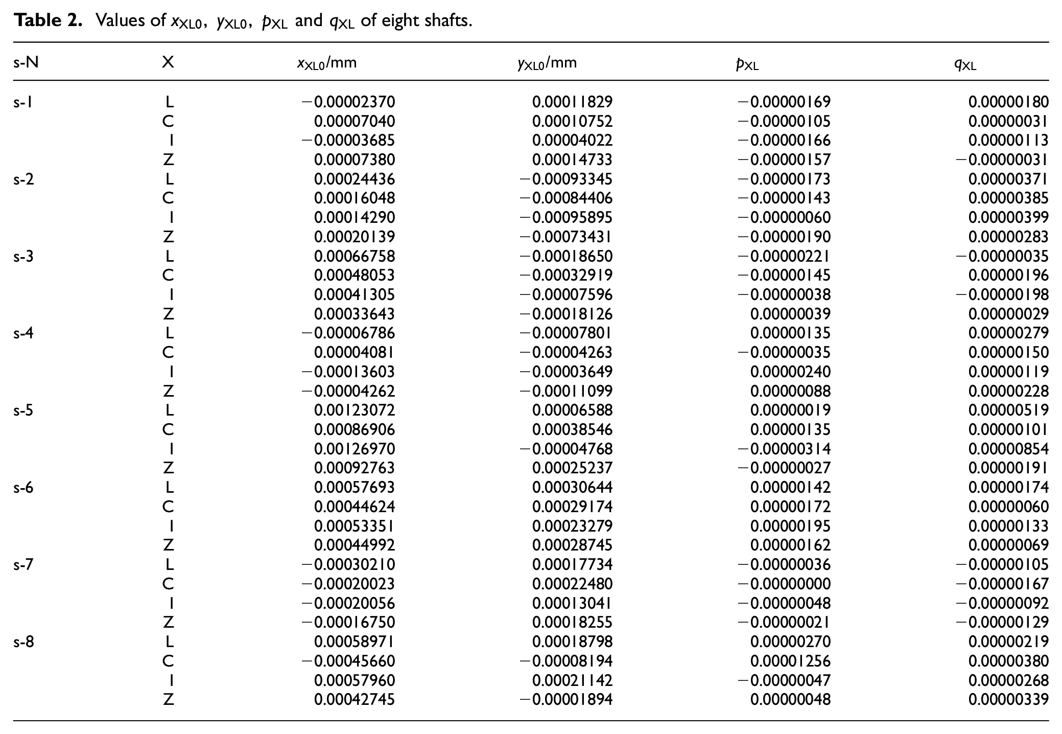
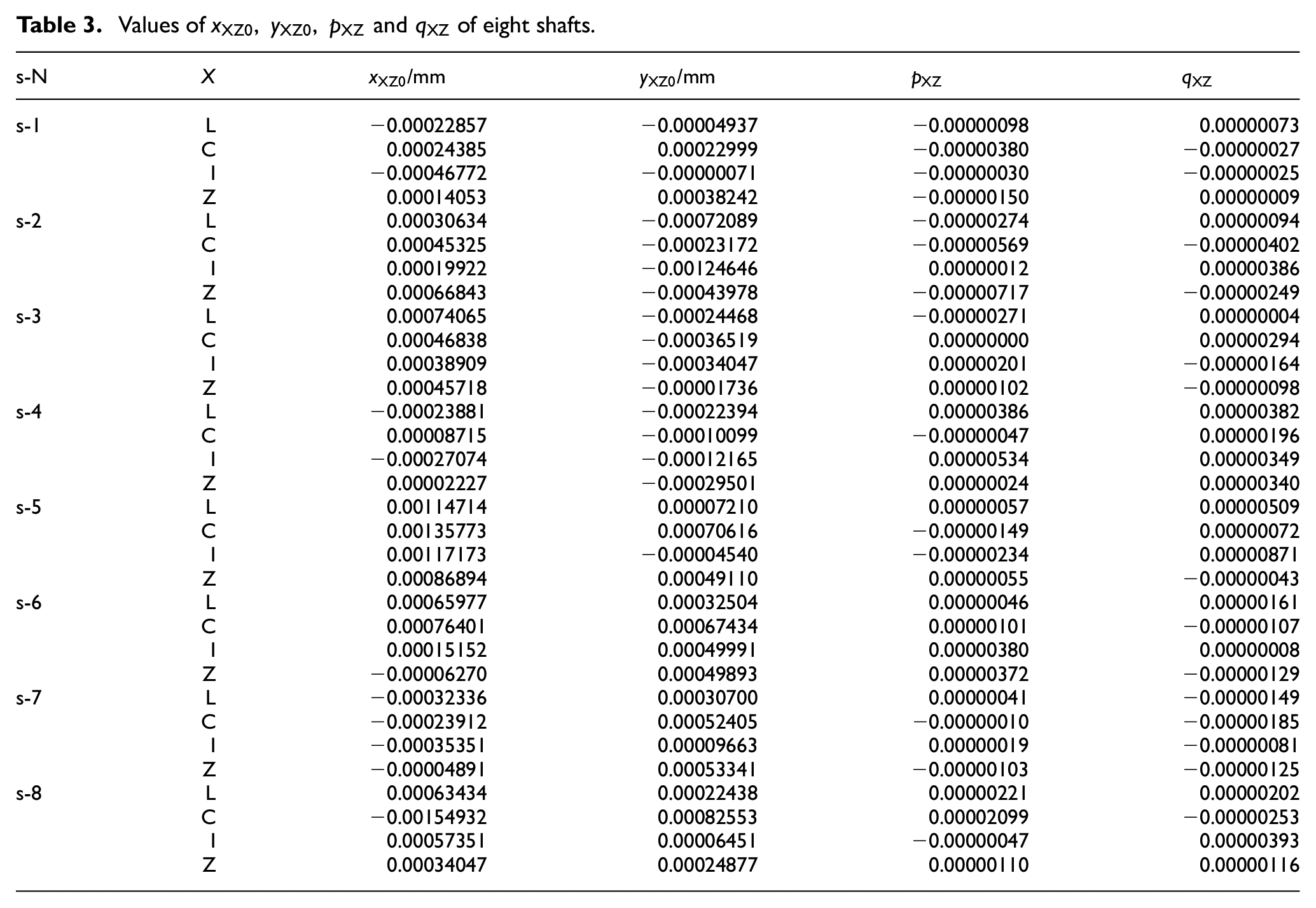
For further researching the influence of the different reference circles on the evaluation results of axis straightness errors of cylindrical parts, the cylindrical roundness profiles of eight holes and eight shafts were extracted by using Talyrond 585LT under the measurement parameters in Table 1. The extracted cylindrical features of eight holes are shown in Figure 7, and the extracted cylindrical features of eight shafts are shown in Figure 8, where the local magnifications of the roundness profiles are 1000 and 2000 for holes and shafts, respectively. It must be pointed out that the roundness profiles of holes and shafts in Figures 7 and 8 are not the ones displayed according to a uniform scale in the radial and height directions and that they were schematically generated by the developed program. Based on the same algorithm as the previous one, the least-square axis parameters xXL0, yXL0, pXL, and qXL and the minimum zone axis parameters xXZ0, yXZ0, pXZ, and qXZ of eight holes can be obtained, and their corresponding least-square axis straightness errors fXL and minimum zone axis straightness errors fXZ can be seen in Figure 9(a). The least-square axis parameters xXL0, yXL0, pXL, and qXL and the minimum zone axis parameters xXZ0, yXZ0, pXZ, and qXZ of eight holes and eight shafts are shown in Tables 2 and 3, respectively, and the corresponding least-square axis straightness errors fXL and the minimum zone axis straightness errors fXZ of eight shafts can be seen in Figure 10(a). The fXV/fLL values of holes and shafts are shown in Figures 9(b) and 10(b), respectively, and the fXZ/ fXL values of holes and shafts are shown in Figures 9(c) and 10(c), respectively.
The measuring parameters of the holes and shafts.
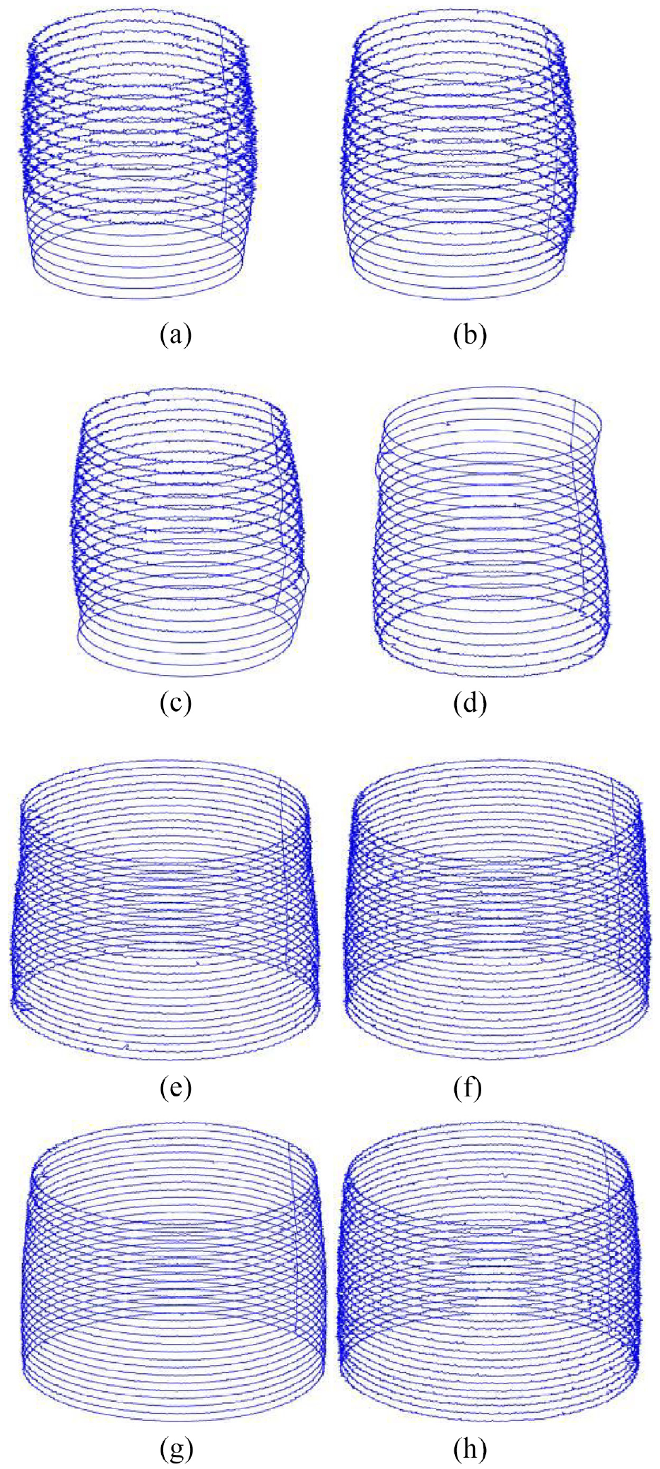
The schematic of the extracted roundness profiles of eight holes: (a) h-1 (ϕ50), (b) h-2 (ϕ50), (c) h-3 (ϕ50), (d) h-4 (ϕ50), (e) h-5 (ϕ80), (f) h-6 (ϕ80), (g) h-7 (ϕ80), and (h) h-8 (ϕ80).
The schematic of the extracted roundness profiles of eight shafts: (a) s-1 (ϕ50), (b) s-2 (ϕ50), (c) s-3 (ϕ50), (d) s-4 (ϕ50), (e) s-5 (ϕ120), (f) s-6 (ϕ120), (g) s-7 (ϕ120), and (h) s-8 (ϕ120).
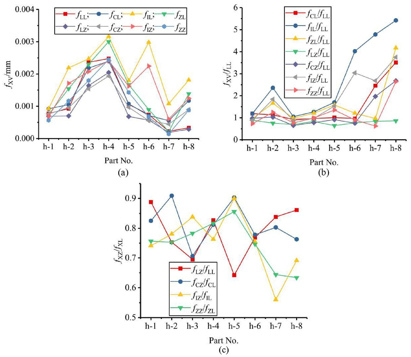
Evaluation results of axis straightness errors of eight holes in Figure 7: (a) fXV, (b) fXV/fLL, and (c) fXZ/fXL.
Values of
Values of
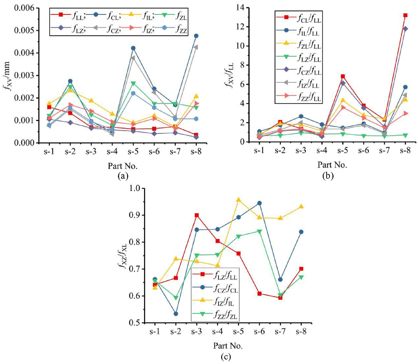
Evaluation results of axis straightness errors of eight shafts in Figure 8: (a) fXV, (b) fXV/fLL, and (c) fXZ/fXL.
Discussion
From Figure 6 we can know that there are obvious differences among the evaluation results of axis straightness errors based on the center coordinates of four reference circles for eight simulated cylinders. For eight simulated cylinders, the axis straightness error fLZ evaluated based on the center coordinates of LSC and the minimum zone criterion is the least one among eight values evaluated according to the center coordinates of four kinds of reference circles and two evaluation criteria, as shown in Figure 6(a). The ratio of the maximum and minimum fXV values of each cylinder is located between 1.3366 and 1.0874 for eight cylinders, and the average value of eight ratio values is 1.2757. Except for fLZ, other fXV values did not exhibit a regular pattern. The fXV/fLL and fXZ/fXL dimensionless values in Figure 6 (b) and (c) are distributed between 0.751 and 1.11 and between 0.751 and 0.972, respectively, and their average values are 0.942 and 0.865, respectively, which further indicates that there are significant differences in the evaluation results of axis straightness errors based on the center coordinates of the different reference circles and different evaluation criteria.
From Figures 9 and 10, we can know that there still exists significant difference of axis straightness errors evaluated based on the centers’ coordinates of different reference circles and different evaluation criteria for a cylindrical part. Among LSC, MCC, MIC, and MZC, the axis straightness error evaluated based on the center coordinates of LSC and the minimum zone criterion is the least for holes and shafts except for h-1, h-3, h-4, s-1, and s-4, the largest, smallest and average values of the hole’s fXV/fLL values in Figure 9(b) are about 5.424, 0.642, and 1.562, respectively, and their above corresponding values of the shaft’s fXV/fLL values in Figure 10(b) are about 13.349, 0.593, and 2.288, respectively. On the other hand, the largest, smallest, and average values of the hole’s fXZ/fXL values in Figure 9(c) are about 0.909, 0.56, and 0.775, respectively, and their above corresponding values of the shaft’s fXV/fLL values in Figure 10(c) are about 0.9, 0.593, and 0.752, respectively. From the above statistical analysis of fXV, fXV/fLL, and fXZ/fXL values in Figures 6, 9 and 10 we can know that the corresponding characteristic values of fXV/fLL values for cylinders, holes and shafts vary widely, and their differences of the corresponding characteristic values of fXZ/fXL values are relatively small. The above analysis results may be decided by whether there are the few singularities in the few roundness profiles of the cylindrical feature. Owing to that there are no singularities in the roundness profiles of the cylinders in Figure 5, comparing with the fXV/fLL and fXZ/fXL values of the measured holes and shafts, their corresponding fXV/fLL and fXZ/fXL values have strong distribution characteristics. However, since there are some singularities in a few roundness profiles of some holes and shafts in Figures 7 and 8, their corresponding fXV/fLL values have no strong distribution characteristics, but the corresponding fXZ/fXL values of holes and shafts have similar distribution characteristics. In a word, the reference circles and the evaluation criteria have great influence on the evaluation results of the axis straightness errors, and when there are some singular points in the roundness profiles, the influence on the evaluation result may be greater.
Conclusions
The evaluation models of the center coordinates of the reference circles, such as LSC, MCC, MIC, and MZC, were built based on their roundness profiles of the cylindrical parts. On the basis of the above center coordinates, the evaluation models of the axis straightness errors of the cylindrical parts were established by using the least-square criterion and the minimum zone criterion. According to the above models and EO algorithm, the evaluation program of axis straightness errors were developed, and the axis straightness errors fXV of eight simulated cylinders, eight holes and eight shafts, measured by using Talyrond 585LT, were evaluated based on the different reference circles and the different evaluation criteria, and their fXV/fLL and fXZ/fXL values were calculated and analyzed. The analysis results showed that both the reference circles and the evaluation criteria have much influence on the evaluation results of the axis straightness errors, and that the axis straightness error evaluated based on the center coordinates of LSC and the minimum zone criterion is the least one for the simulated cylinders and most of the measured holes and shafts. On the other hand, when there are some singularities in a few of roundness profiles of holes or shafts, their corresponding characteristics of the fXV/fLL values may vary widely, otherwise, the difference of their corresponding characteristics may be smaller, but the influences of the singularities in the roundness profiles on their corresponding characteristics of the fXZ/fXL values may be relatively stable. Therefore, whether or not there are singularities in a few of roundness profiles, the differences among the evaluation results of the axis straightness errors based on the center coordinates of the different reference circles and the different evaluation criteria are still large. The research will help the designer to indicate the proper reference circle and evaluation criterion when the axial straightness error is evaluated according to the functional requirements of the part.
Footnotes
Declaration of conflicting interests
The author(s) declared no potential conflicts of interest with respect to the research, authorship, and/or publication of this article.
Funding
The author(s) disclosed receipt of the following financial support for the research, authorship, and/or publication of this article: This project is supported by National Natural Science Foundation of China (Grant No. 51975598, 51475485).