
Abstract
The single axis linear displacement measurement system of CMM is composed of grating ruler, servo motor and linear motion mechanism. Although the measuring accuracy of grating ruler is high, the accuracy of servo motor and linear motion mechanism is low. Therefore, the complex structure limits the measurement accuracy of the linear displacement measurement system. This paper introduces a novel linear displacement measurement system named magnetic levitation ruler. According to the working principle of grating ruler and the characteristics of magnetic levitation technology, the magnetic circuit design and structural design of magnetic levitation ruler are completed in this paper. The mover core of the magnetic levitation ruler is in the stable working magnetic field provided by the stator yoke. The horizontal control coil wound on the mover core can obtain more stable ampere force to improve the control accuracy of the mover core displacement. Therefore, the mover core can be moved in step mode, and the length of each step is fixed. Each step is the minimum scale of the magnetic levitation ruler. Therefore, the mover core can implement displacement measurement while moving in a linear motion. This paper analyzes the working principle of levitation, horizontal motion, and displacement measurement of magnetic levitation ruler, and determines the structural materials and parameters of magnetic levitation ruler with the help of finite element analysis software. The simulation results show that the levitation force of the magnetic levitation ruler is proportional to the current passing through the levitation coils, and the thrust of the horizontal control coil is less disturbed by the magnetic field. Compared with the linear displacement measurement system with rotational servo motor or permanent magnet synchronous linear motor as the core, the magnetic levitation ruler has stable magnetic field, strong controllability, high integration, and is easier to achieve high-precision control.
Introduction
With the continuous progress of industry, the quality requirements of free-form surface parts are also improving. CMM is a measuring instrument used for space measurement, which can measure free-form surface parts. It mainly includes three linear displacement measurement systems of X, Y, and Z axes, probe system, electrical control system and data processing software. The linear displacement measurement system mainly includes grating ruler, servo motor and linear motion mechanism. 1 Although the accuracy of grating ruler is high, the accuracy of servo motor and linear motion mechanism is low. Therefore, the complex structure of servo motor and linear motion mechanism limits the measurement accuracy of the linear displacement measurement system. In addition, servo motor and linear motion mechanism have large mass, resulting in greater moment of inertia, so high-power servo motor is required. There is unnecessary energy consumption in the system.
Permanent magnet linear synchronous motor (PMLSM) can be an alternative solution to rotational motor in linear displacement measurement system. It can provide linear motion for linear displacement measurement system without any mechanical interface. The measurement accuracy of the linear displacement measurement system is improved due to the use of permanent magnet linear synchronous motor. 2 Permanent magnet synchronous linear motor can be considered as a permanent magnet synchronous rotating motor which is split along the radial direction and then flattened. After the permanent magnet synchronous rotary motor is flattened into a permanent magnet synchronous linear motor, its motion principle is slightly different. First of all, the magnetic circuit is no longer closed after flattening, which causes the longitudinal end effect of permanent magnet synchronous linear motor. Secondly, in the permanent magnet linear synchronous motor, the air gap magnetic field changes from circular motion to linear motion. The air gap magnetic field is called traveling wave magnetic field, which interacts with the excitation magnetic field generated by the permanent magnet to generate electromagnetic thrust. 3 Under the action of electromagnetic thrust, since the stator is fixed, the mover will move in a linear motion in the opposite direction of the traveling magnetic field. 3 When the three-phase symmetrical sinusoidal current flows through the three-phase winding of the permanent magnet synchronous rotating motor, a sinusoidal rotating magnetic field will be generated in the air gap. 3 After the permanent magnet linear synchronous motor is powered on, it will also produce a sinusoidal magnetic field in the air gap in the horizontal direction, which is called traveling magnetic field.3–7 The sinusoidal traveling magnetic field and the sinusoidal current in the coil cause the electromagnetic thrust to fluctuate greatly. With the help of the grating ruler and the precise control algorithm, the permanent magnet synchronous linear motor can implement the accurate positioning.
The voice coil motor has a very simple structure and there is no mechanical contact between the mover and the stator, it does not suffer from friction or backlash, resulting in high precision and a rapid response. 8 Moreover, the generated magnetic force is proportional to the current that flows along the coil, which is suitable for precision control. 8 However, the voice coil motor has the drawback of weaker force compared to its volume than contact-type actuators such as piezoelectric, magnetostrictive, and electrostrictive actuators. 8 A moving component should always be levitated in a maglev positioning system, so the actuators should generate greater force than the weight of the moving component. 8 In particular, voice coil motor is widely used as an actuator in a maglev device in order to implement nanometer-level precision in a short stroke.8–15
Zhenxiong proposed a TU magnetic levitation positioning platform.16–20 The magnetic levitation positioning platform has a U-shaped stator. The T-shaped mover moves in the U-shaped space. The T-shaped mover is wound with coils to generate horizontal thrust. The basic levitation force is generated by the permanent magnet of the platform. The three levitation control coils on the stator generate magnetic fields to adjust the levitation force on the mover. The advantage of this magnetic levitation positioning platform is that it has an energy-saving variable reluctance levitation system, which uses the permanent magnet to provide the reluctance force generated by magnetic bias for the air gap as the main levitation force of the mover, while the levitation control coils are only used to regulate the magnetic bias, which can greatly reduce the energy consumption of the levitation system. The positioning platform uses an extended cross magnetic conductor to provide horizontal degrees of freedom, so as to realize multi degree of freedom movement on the plane. The degree of freedom of movement allows long orthogonal straight lines and angular travel. Permanent magnet bias is applied to the positioning platform to obtain high thrust acceleration and high position stability. The structure of the mover and stator is simple and easy to manufacture. Compared with voice coil motor, the constant magnetic bias generated by permanent magnet can obtain greater thrust. Compared with the permanent magnet synchronous linear motor, the constant magnetic bias generated by permanent magnet can obtain higher position stability. However, levitation control coils cannot regulate the reluctance force of upper air gap and lower air gap of the mover at the same time, and cannot completely remove external interference. Therefore, the positioning accuracy of TU maglev positioning platform is limited. 17
On the basis of TU magnetic levitation positioning platform, a novel linear displacement measurement system, magnetic levitation ruler, is proposed in this paper. Different from the TU magnetic levitation positioning platform, the magnetic fields of upper air gap and lower air gap of the mover core of the magnetic levitation ruler can be controlled separately through levitation control coils. While upper air gap magnetic field is controllable, lower air gap magnetic field is also controllable, so as to the magnetic fields of upper air gap and lower air gap are relatively stable.
The horizontal control coil of the magnetic levitation ruler is wound on the mover core and passes through the air gap magnetic field. When the current passes through the horizontal control coil, the horizontal control coil will generate thrust to push the mover core to move horizontally. The air gap magnetic field is stable, and the current passing through the horizontal control coil is stable, so the thrust force on the mover core is stable. Therefore, the length of the motion of mover core is precisely controllable. The mover core of the magnetic levitation ruler can move in a straight line step by step. The length of each step can be fixed, which is called step length. Each step is the minimum scale of the magnetic levitation ruler. Therefore, the mover core can implement displacement measurement while moving in a linear motion.
The organization of this paper is as follows. In Section II, the structure of the magnetic levitation ruler is designed, and the working principle of the magnetic levitation ruler is analyzed. In Section III, the magnetic circuit of the magnetic levitation ruler is designed and analyzed. In Section IV, the magnetic characteristics of the magnetic levitation ruler are analyzed by finite element method. Section V, the modal analysis of the mover core is carried out. Finally, conclusions are presented in Section VI.
Structure design and working principle analysis of magnetic suspension ruler
Structure design of magnetic levitation ruler
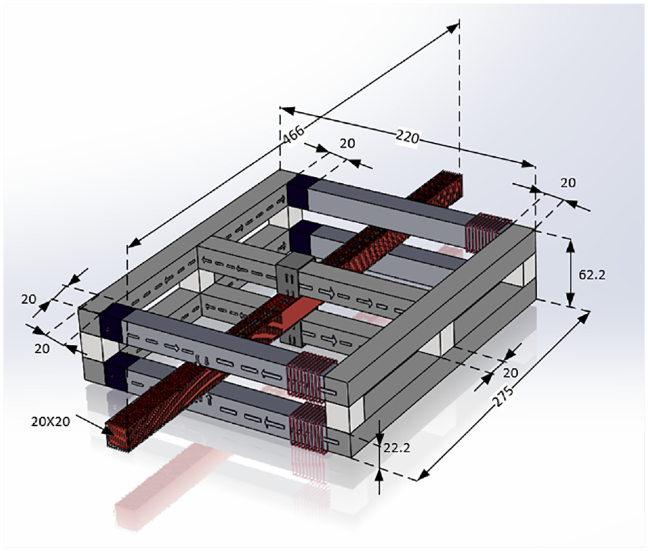
This paper proposes a magnetic levitation ruler system, its structure is shown in Figure 1.
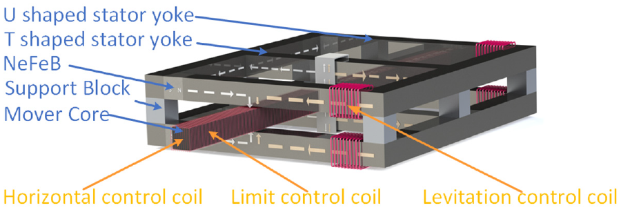
Structure of magnetic levitation ruler.
As shown in Figure 1, the system is mainly composed of stator yokes, a mover core and drive coils. Stator yokes are divided into upper layer and lower layer with the same structure. To facilitate the installation of permanent magnets, each layer of stator yoke can be further decomposed into a T-shaped stator yoke and a U-shaped stator yoke. The cross arm of the T-shaped stator yoke is parallel to the bottom cross arm of the U-shaped stator yoke. The vertical arm of the T-shaped stator yoke is parallel to the two side arms of the U-shaped stator yoke. Therefore, stator yokes are composed of two T-shaped stator yokes and two U-shaped stator yokes. Each U-shaped stator yoke has two top ends, and four permanent magnets are installed on four top ends of two U-shaped stator yokes. Six magnetic isolation support blocks are used between two stator yokes to separate upper magnetic circuits and lower magnetic circuits on the one hand, and provide motion space for the mover core on the other hand.
The mover core is located between upper stator yokes and lower stator yokes, parallel to the bottom of U-shaped stator yokes. The mover core is wound with horizontal control coil and limit control coil. Levitation control coils are wound around the end of arms on both sides of U-shaped stator yokes. Set the X axis direction as the direction of the transverse arm of the T-shaped stator yoke. Set the Y axis direction as the direction of the vertical arm of the T-shaped stator yoke.
Analysis of the working principle of magnetic levitation ruler
Eight closed magnetic circuits of the magnetic levitation ruler were established. Four basic levitation magnetic circuits and their fluxes are generated from four permanent magnets; four control levitation magnetic circuits are sent out by four levitation control coils. The horizontal control coil uses the magnetic field formed by eight closed magnetic circuits to generate ampere force to control the horizontal motion of the mover core. The mover core can drive the load to move horizontally.
According to the calculation formula of ampere force and the relationship between force and displacement, the stability of both the air gap magnetic field and the current in the horizontal control coil determines the accuracy of horizontal motion and length of step. The working principle of the magnetic levitation ruler is described in detail below.
Firstly, the analysis of the working magnetic field of the magnetic levitation ruler is introduced.
The magnetic levitation ruler established the working magnetic field through four basic levitation magnetic circuits and four control levitation magnetic circuits.
Magnetic fluxes of four basic levitation magnetic circuits start from four permanent magnets, propagate alongside arms of U-shaped stator yokes, pass through the air gap between the side arm of U-shaped stator yokes and the mover core, and propagate in the mover core, then pass through the air gap between the mover core and the vertical arm of T-shaped stator yokes, and continue to propagate along T-shaped stator yokes, and finally return to permanent magnets.
Magnetic fluxes of four control levitation magnetic circuits start from four control levitation coils, propagate alongside arms of U-shaped stator yokes, pass through the air gap between the side arm of U-shaped stator yokes and the mover core, and propagate in the mover core, then pass through the air gap between the mover core and the vertical arm of T-shaped stator yokes, propagate along the vertical arm of T-shaped stator yokes, and continue to propagate along the bottom of U-shaped stator yokes, and finally return to levitation control coils.
Because the reluctance of permanent magnets is very large, magnetic fluxes from the levitation control coils cannot pass through the permanent magnets to form closed magnetic circuits. The magnetic potential of the levitation control coils is high, so magnetic fluxes from permanent magnets cannot pass through levitation control coils to form closed magnetic circuits. Moreover, six support blocks are made of magnetic isolation materials, and upper stator yokes and lower stator yokes cannot form closed magnetic circuits. Therefore, eight closed magnetic circuits are independent closed magnetic circuits. The interrelationship between them is negligible.
Next, the analysis of working principle of levitation control coils is introduced.
Magnetic fluxes of four basic levitation magnetic circuits are start from permanent magnets, and the density and the direction of magnetic fluxes are fixed. Magnetic fluxes of control levitation magnetic circuits are start from levitation control coils, and the density and the direction of magnetic fluxes are determined by the magnitude and direction of the current passing through the levitation control coils. According to Kirchhoff’s first law of the magnetic circuit, magnetic fluxes propagating in the air gap are composed of the magnetic fluxes of basic levitation magnetic circuits and magnetic fluxes of the control levitation magnetic circuits. As shown in Figure 2.
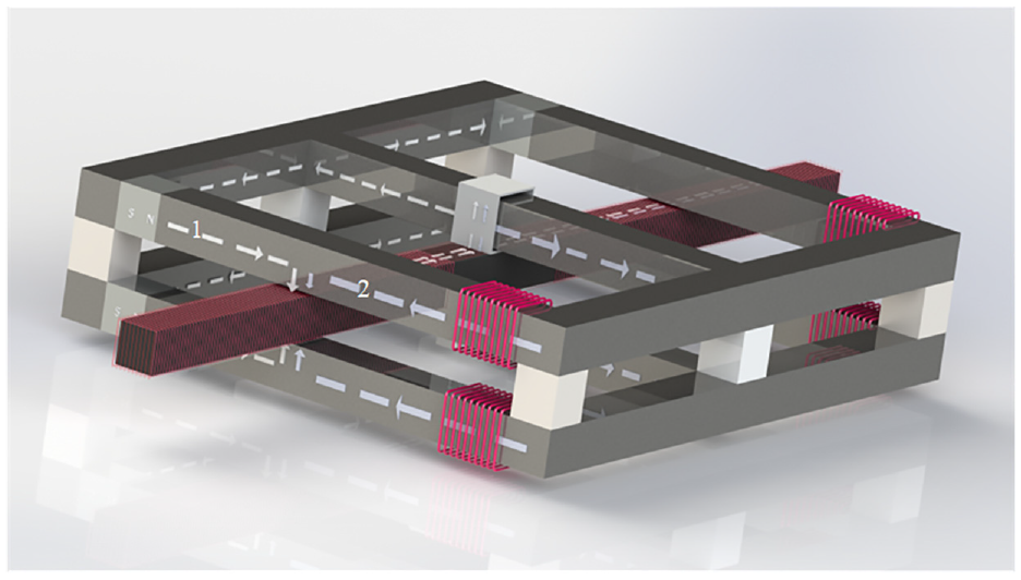
Superposition of basic levitation magnetic circuit and control levitation magnetic circuit.
The No. 1 magnetic circuit in Figure 2 is the basic levitation magnetic circuit, and the No. 2 magnetic circuit is the control levitation magnetic circuit. In this paper, the working principle of levitation control coils is explained by taking magnetic circuit 1 and magnetic circuit 2 as examples.
The No. 1 magnetic circuit and No. 2 magnetic circuit coincide at upper air gap of the mover core. According to Kirchhoff’s first law of magnetic circuit, the air gap flux is the sum of the flux from the permanent magnet of No. 1 magnetic circuit and the flux from the levitation control coil of No. 2 magnetic circuit. Affected by the length, density and external interference of the magnetic circuit, the magnetic flux from the permanent magnet of No. 1 magnetic circuit will change when it propagates to the mover core. The magnetic flux from the permanent magnet of No. 1 magnetic circuit is uncontrollable, and the magnetic flux of air gap cannot be adjusted to ensure the magnetic flux of air gap is a constant. By controlling the current on the levitation control coil of No. 2 magnetic circuit, the magnetic flux of No. 2 magnetic circuit can be adjusted to control the magnetic flux of air gap. Therefore, the magnetic induction intensity of the air gap is stabilized to a certain target value to stabilize the working magnetic field.
If the levitation height of the mover core needs to be adjusted, the electromagnetic attraction on the mover core needs to be adjusted. The magnitude of the electromagnetic attraction on the mover core is related to magnetic fluxes of upper air gap and lower air gap, that is, adjusting the current of four levitation control coils can affect magnetic fluxes of air gap, so as to adjusting the electromagnetic attraction on the mover core to keep the levitation height stable.
Finally, the working principle analysis of horizontal control coil is introduced.
The horizontal control coil is wound on the mover core, as shown in Figure 3.
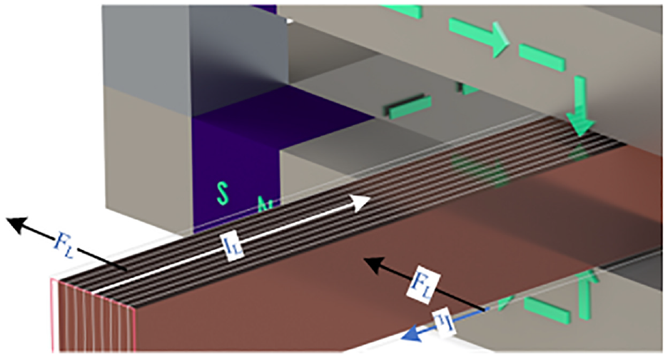
Working principle of horizontal control coil.
From the perspective of Figure 3, clockwise current IL flows into the horizontal control coil. The magnetic field in the air gap at the upper side of the mover core is downward. According to the left-handed rule, upper wires of the horizontal control coil generate an ampere force FL in the negative direction of Y-axis. The magnetic field in the air gap at the lower side of the mover core is upward. According to the left-handed rule, lower wires of horizontal control coil generates an ampere force FL in the negative direction of Y axis. As the mover core is in levitation, the air resistance can be ignored in rough calculation. Therefore, in an ideal state, the force on the mover core in the Y-axis direction is only FL, that is, the mover core moves along the Y-axis under the ampere force FL. The direction of movement is determined by the direction of FL.
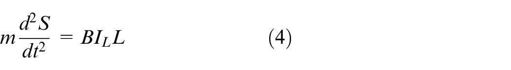
In case of rough calculation, the calculation formula of ampere force is as follows:

Where FL represents the electromagnetic thrust, B represents the magnetic induction intensity at the horizontal control coil, IL represents the current intensity in the horizontal control coil, and L represents the length of the wire in the magnetic field. If the air gap magnetic field is constant, FL is proportional to IL.
Newton’s second law is as follows:

Where m represents the mass of the mover core, and a represents the acceleration of the mover core under the FL. The acceleration has the following relationship with the independent displacement S of the mover core:
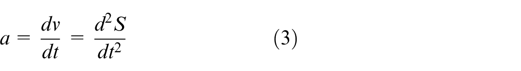
Based on the equations (1)–(3), the equation of the S is established as follows:
In this paper, the mover core moves along the Y axis step by step, and the length of each step is fixed. That means the mover core moves along the Y axis under the FL in a fixed time, t represents this fixed time, and then, the mover core continues to move along the Y axis and stop under the negative FL in a t time. The mover core moves twice as far as S in these 2t times. At both ends of the equation, take double definite integral in 0t time. Therefore, the equation of S established as follows:
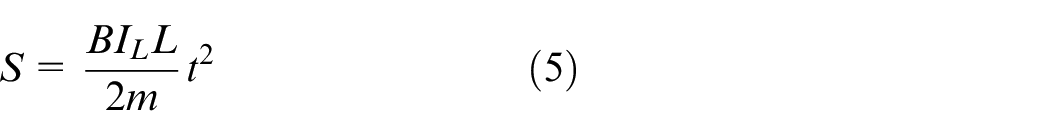
In the formula, the mass m of the mover core and the wire length L of the horizontal control coil in the magnetic field can be approximately regarded as constants. Then the accuracy of the displacement S of the mover core is related to the magnetic induction intensity B of the air gap magnetic field and the accuracy of the current IL of the horizontal control coil.
The mover core of the magnetic levitation ruler designed in this paper displaces step by step automatically, and the length of each step is fixed. The length of each step is the scale of the magnetic levitation ruler. Therefore, the accuracy of the magnetic levitation ruler is related to the accuracy of displacement S of the mover core.
The limit control coil is used to control the position of the mover core in the X axis direction. If the mover core moves in the Y direction and there is a position deviation on the X axis, the limit control coil will be energized to eliminate the deviation of the mover core in the X axis. The magnetic levitation ruler does not require high displacement accuracy of the mover core on the X axis. Therefore, this article will not elaborate specifically.
Driving force analysis of mover core
The driving force on the mover core and its direction are shown in Figure 4.
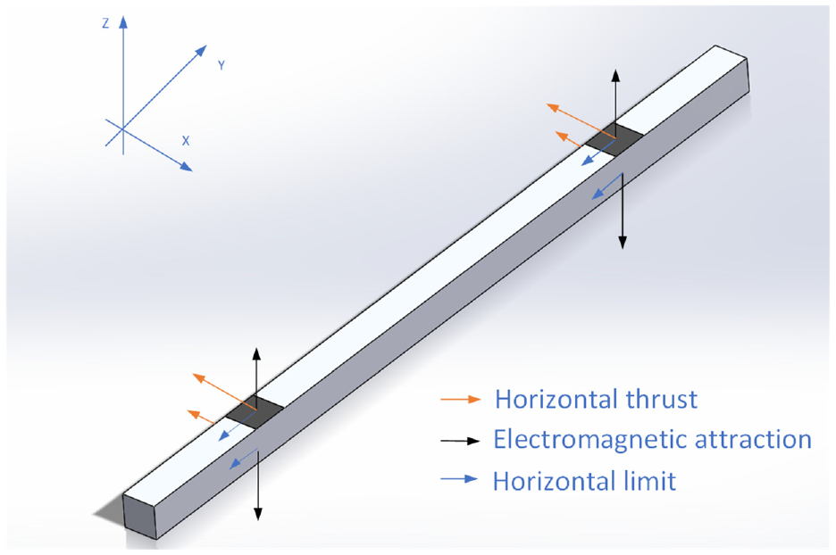
Driving force on the mover core and its direction.
The box in the figure is the mover core. Looking down from the Z axis, the black area on the mover core is the area where the U-shaped magnet and the mover core intersect. Magnetic fluxes from the permanent magnets enter the mover core in the black area above and below the mover core through the U-shaped stator yokes and air gap. The black arrow indicates the electromagnetic attraction on the mover core. As shown in Figure 4, the action points of electromagnetic attraction on the left and right sides of the mover core form two fulcrums of the mover core. In addition, the orange arrow indicates the horizontal thrust generated by the horizontal control coil, and the blue arrow indicates the ampere force generated by the limit control coil.
Design and analysis of magnetic circuit of magnetic levitation ruler
The mover core, U-shaped stator yokes and T-shaped stator yokes of the magnetic levitation ruler are all magnetic yokes. The size of each magnetic yoke affects the stability and accuracy of the magnetic levitation ruler. In order to ensure the optimal size of all magnetic yokes, a system model should be established for the magnetic levitation ruler. However, during the establishment of the system model of the magnetic levitation ruler, the following factors have affected the establishment of the model: when lengths of air gap are large, the magnetic flux divergence is easy to occur at the edge of the magnetic conductive parts; when the magnetic flux density of the stator yoke is too high, the stray magnetic flux will be too high; usually, the relationship of electromagnetic attraction and square of air gap are linear, and the existence of magnetic saturation and stray flux affects their linearity; the working magnetic field of the magnetic levitation ruler is an integrated magnetic field composed of multiple sub magnetic fields. There is coupling between magnetic fluxes of drive coils, so it needs to be decoupled.
It can be seen that the size of each magnetic circuit component in the magnetic levitation ruler cannot be accurately predicted. Therefore, this paper uses approximate calculation and finite element analysis of magnetostatic field to complete the magnetic circuit design and analysis of the system.
Material selection of magnetic circuit components
According to the control requirements of the magnetic levitation ruler, the magnetic circuit components should be made of materials with low heating, low hysteresis loss, high permeability, and easy demagnetization. Therefore, ferromagnetic materials can be selected for stator yokes and mover core of magnetic circuit. For example: pure iron, carbon steel, silicon steel, etc.
In this paper, laminated silicon steel sheet was used as the magnetic material of stator yokes. The laminated silicon steel sheet has high magnetic permeability and can significantly reduce eddy current loss. This paper selected 30ZH120 cold rolled silicon steel sheet. This type of silicon steel sheet belongs to laminated silicon steel sheet. It has good magnetic conductivity, low loss, high resistivity, 0.3 mm thickness, low eddy current loss, and good permeability. The saturation characteristics of this material are shown in Figure 5.
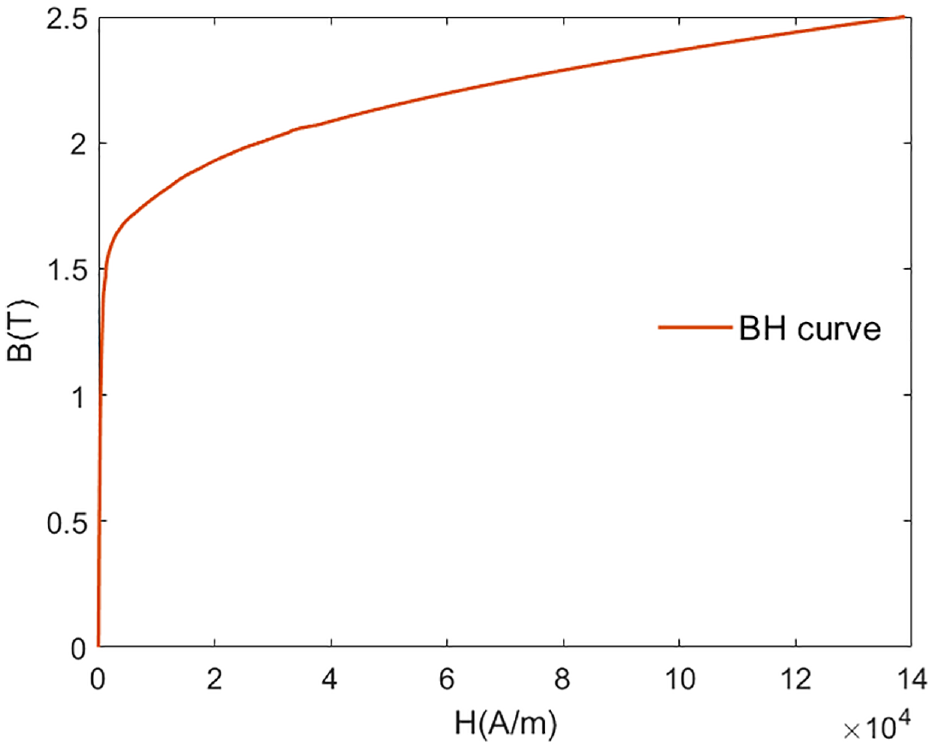
BH curve of silicon steel sheet.
In the design of magnetic circuit, the magnetic isolation support block and support foundation of the system should also be designed. The support block and support foundation are made of materials with good magnetic isolation effect, good rigidity and easy processing. Therefore, aluminum was selected to make the support block and support foundation. In this paper, pure iron DT4 was selected as the material of mover core. When it is magnetically unsaturated, its relative permeability is high and its coercivity is small. Pure iron is a soft magnetic material, and its magnetic field is prone to alternating.
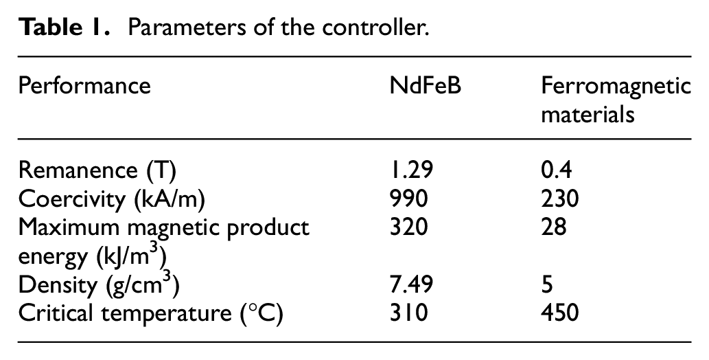
Demagnetization of permanent magnets has a great impact on the system. In this paper, Nd2Fe14B permanent magnet with high coercivity and high cost performance ratio was used, and the model is BM35. Its performance comparison with that of ferromagnetic materials is shown in Table 1.
Parameters of the controller.
The demagnetization curve of NdFeB is shown in Figure 6.
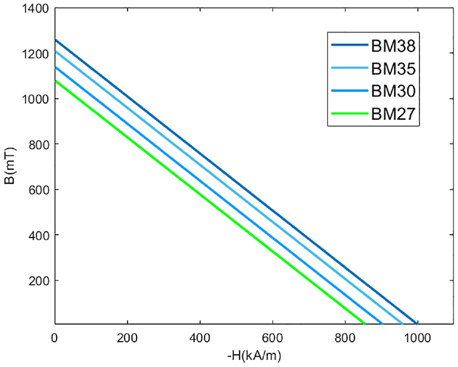
Demagnetization curve of NdFeB.
According to the mass of the mover core, lengths of the air gap of the magnetic circuit and the parameters of the permanent magnet, the minimum length of the permanent magnet was estimated to be 5 mm. In practical application, the mover core should be in the nearly saturated magnetic bias state. Therefore, the length of permanent magnet selected for magnetic levitation ruler was 10 mm.
In this paper, ANSYS was used to simulate the magnetostatic field of magnetic circuits of the magnetic levitation ruler. The simulation results of magnetic induction intensity on contact surfaces of permanent magnets and U-shaped stator yokes are shown in Figure 7. Thus, the magnetic potential of contact surfaces of permanent magnets can be obtained. If the length of permanent magnets exceeds the required length, the surplus magnetic fluxes will be lost.
The average magnetic field intensity on the surfaces of four permanent magnets.
Estimation of the length of magnetic circuits and the size of magnetic circuit components
The system model used approximate estimation method to select magnetic circuit components of the magnetic levitation ruler, and estimated the magnetic circuit size of the magnetic levitation ruler. The relationship between magnetic induction intensity B and magnetic field intensity H is as follows:

In this paper, the area where the U-shaped stator yoke intersects the mover core is the polar, that is, the black area in Figure 4, and the polar area of the mover core is equal to the polar area of the air gap, which is represented by A, then the calculation formula of the magnetic common energy density of the air gap is as follows:
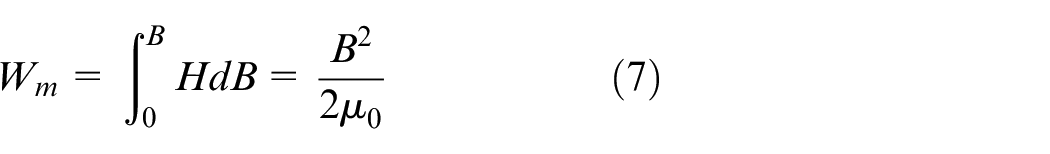
Where μ0 is represents the vacuum permeability. In general, the value of vacuum permeability is the same as that of air permeability. According to equation (7), the air gap magnetic field energy is calculated as follows:
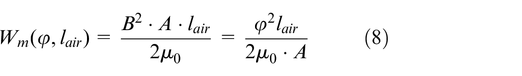
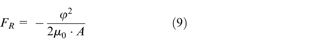
As φ = B · A is known, it can be obtained by substituting φ = B · A into equation (9).
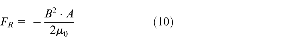
Where, B is represents the magnetic induction intensity at the polar.
In this paper, the area A of the polar was taken as 20 mm × 20 mm, the density of DT4 is 7.85 g/cm3, so it can be seen that the mass of the mover core is about 1.13 kg, and the weight of the sensor is 0.7 kg, and the gravity it receives is about 18 N. The magnetic induction intensity of the polar is about 1.2 T. From equation (10), the maximum electromagnetic attraction FR can reach 229 N, meeting the system requirements.
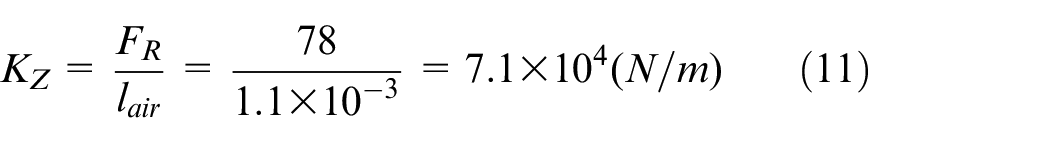
Assuming that the expected value of the nominal magnetic induction intensity of air gap is 0.7 T, the electromagnetic attraction is about 78 N from equation (10), which can also meet the system requirements.
Assuming that lengths of air gap are 1.1 mm, let KZ be the ratio of electromagnetic attraction to lengths of air gap, and its value is:
Based on the above estimates, this paper has designed the dimensions of each component of the magnetic levitation ruler, which are marked in Figure 8.
Dimensioning of all parts (unit: mm).
According to the user’s requirements, the dimensions of each component of the magnetic levitation ruler can be modified, and its structure is simple and convenient for processing.
Finite element analysis of magnetostatic field
In this paper, ANSYS Electronics 19.2 software was used to analyze the magnetic induction intensity distribution of the magnetic levitation ruler and the force on each component of the magnetic levitation ruler.
Firstly, the magnetostatic field analysis of magnetic levitation ruler is introduced.
Lengths of upper air gap and lower air gap were set to be 1.1 mm long. In the finite element simulation of 3D magnetostatic field, after several iterations, the scalar map of magnetic induction intensity was obtained when the mover core had different levitation positions, showing how the magnetic induction intensity is distributed.
Figure 9(a) shows that when the geometric center point of the mover core coincides with the geometric center point of the magnetic levitation ruler, and upper air gap and lower air gap have the same length, that is, center height and center plane position, the magnetic induction intensity distribution of the magnetic levitation ruler is shown in the figure. It can be seen from the figure that the magnetic induction intensity distribution of the mover core is symmetrical. Its upper surfaces and lower surfaces are basically in magnetic saturation state, which ensure the optimal magnetic bias density in the air gap. The magnetic induction intensity of a part of U-shaped stator yokes between levitation control coils and the air gap has not reached the saturation state, so when the magnetic fluxes sent by the levitation control coils pass through the U-shaped stator yokes, saturation is not easy to occur, which is convenient for controlling the levitation of the mover core.
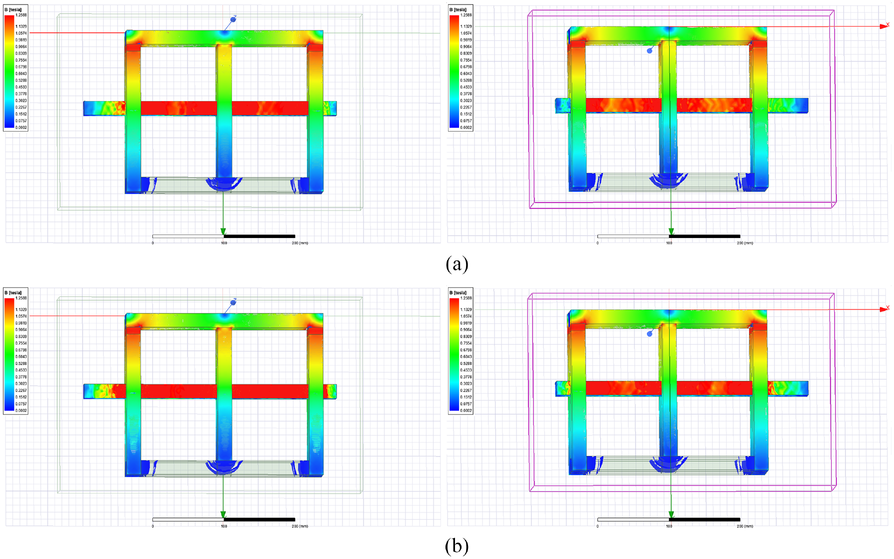
Distribution of magnetic induction intensity: (a) air gaps are same and (b) air gaps are different.
When the mover core moved up 1 mm on the basis of the center height, lengths of upper air gap of the mover core was only 0.1 mm, while lengths of lower air gap of the mover core was 2.1 mm. The difference between upper air gap and lower air gap was obvious. The magnetic induction intensity distribution of the magnetic levitation ruler is shown in Figure 9(b). It indicates that when lengths of upper air gap are significantly different from those of lower air gap after the mover core moves up, the upper surface of the mover core is still in an approximate magnetic saturation state, and the magnetic induction intensity of the lower surface of the mover core decreases.
Next, the trend of magnetic lines of force in U-shaped stator yokes are analyzed by magnetic line of force distribution, as shown in Figure 10.
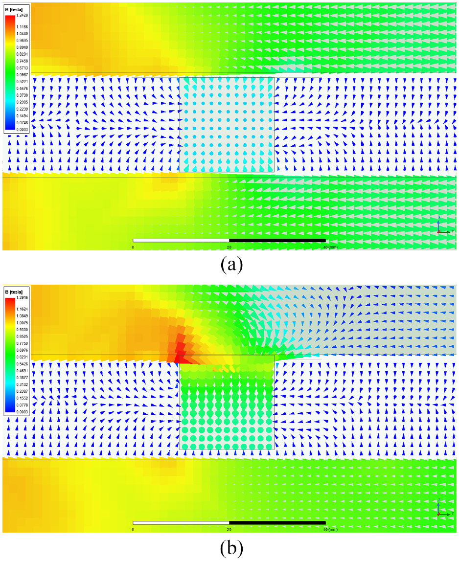
Distribution of magnetic lines of force: (a) air gaps are same and (b) air gaps are different.
Figure 10 shows that when lengths of upper air gap and lower air gap of the mover core are the same, the magnetic field of the magnetic levitation ruler is symmetrically distributed. When the mover core moves up 1 mm, lengths of upper air gap and lower air gap are different, and their reluctance is also different, resulting in the asymmetry between the magnetic induction intensity on the upper surface and the magnetic induction intensity on the lower surface of the mover core.
The simulation results show that lengths of upper air gap and lower air gap of the mover core should be the same during the levitation control of the mover core.
Next, the influence of lengths of air gap on the magnetic induction intensity of the air gap is introduced.
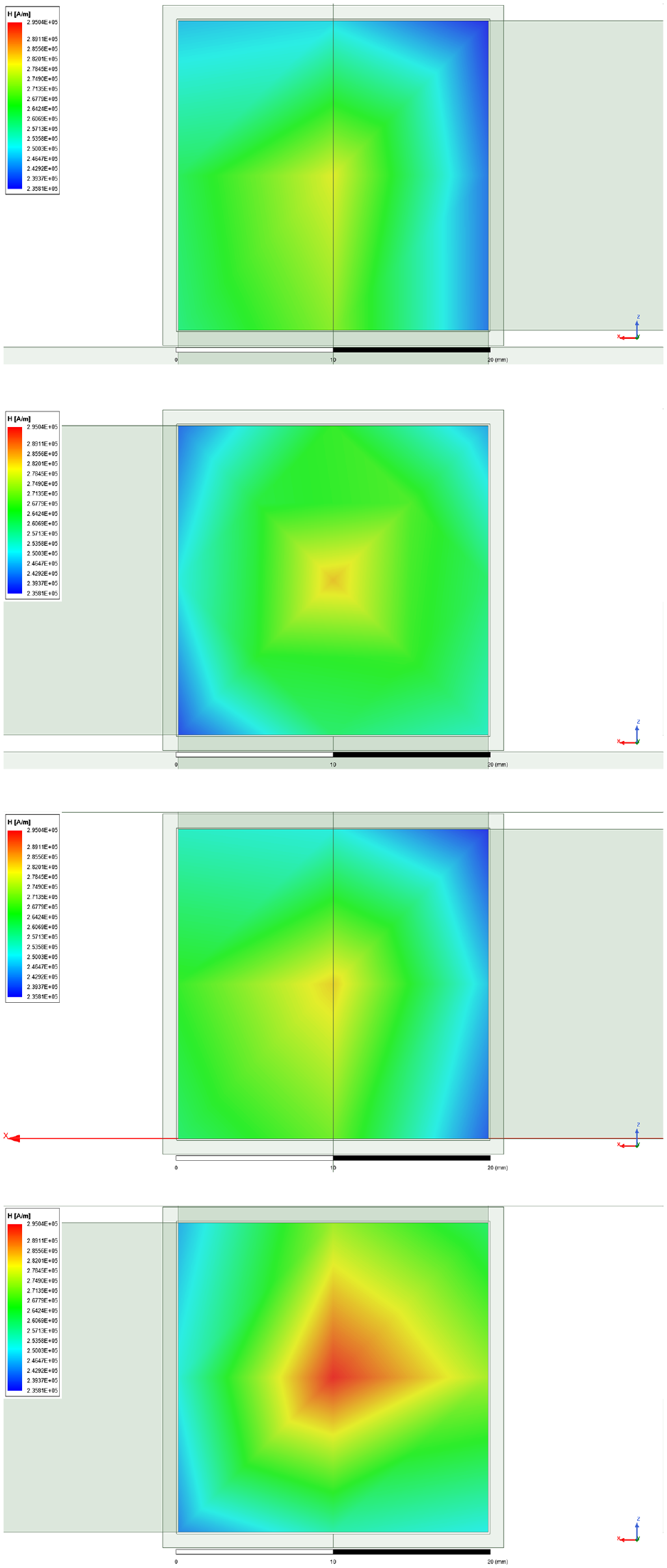
Lengths of air gap of the magnetic levitation ruler have a great influence on the magnetic field in air gap. In this paper, the magnetic field of air gap of the mover core was taken as an example for simulation analysis. Through comparative research on the distribution of the magnetic field of air gap of the mover core when lengths of air gap between the mover core and the U-shaped magnet were 2, 1.5, 1, and 0.5 mm respectively, a scalar diagram of the magnetic induction intensity of air gap of the mover core with different air gap lengths was obtained, as shown in Figure 11.
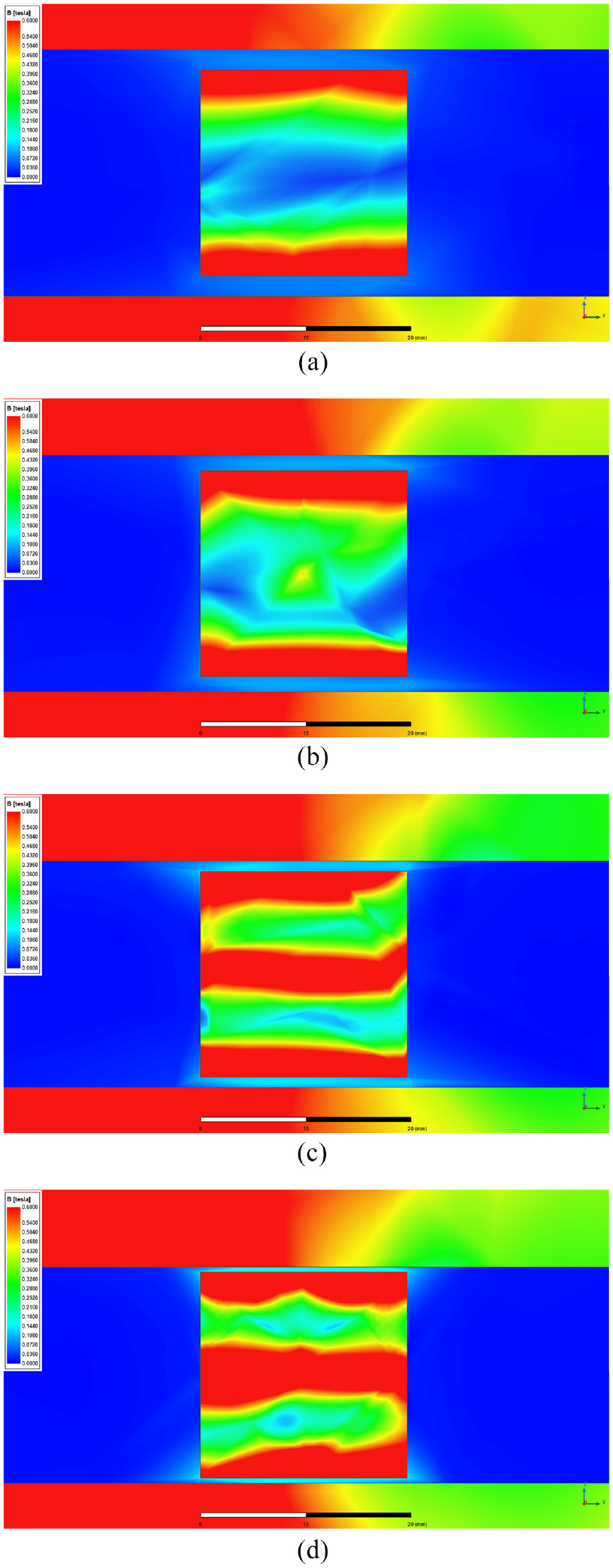
Scalar diagram of air gap magnetic induction intensity at different air gap lengths: (a) 2 mm, (b) 1.5 mm, (c) 1 mm, and (d) 0.5 mm.
When lengths of air gap between the mover core and the U-shaped stator yokes are different, the magnetic induction intensity distribution on both sides of the air gap center line is shown in Figure 12.
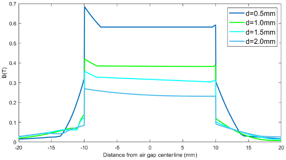
Magnetic induction intensity distribution on both sides of air gap center line.
Levitation control coils and horizontal control coil
The relationship between the electromagnetic attraction generated by the air gap bias of the magnetic levitation ruler and the levitation position, and the relationship between the electromagnetic attraction generated by the levitation control coil and the current of levitation control coil can be calculated by simulation analysis. The sum of the upward electromagnetic attraction and downward electromagnetic attraction on the mover core is the levitation force on the mover core.
In this paper, the left end of the mover core was moved upward with a unit offset of 0.01 mm from the center position to a length of 0–0.1 mm, and the relationship between the levitation position and the magnetic force was obtained through simulation experiments, as shown in Figure 13(a).
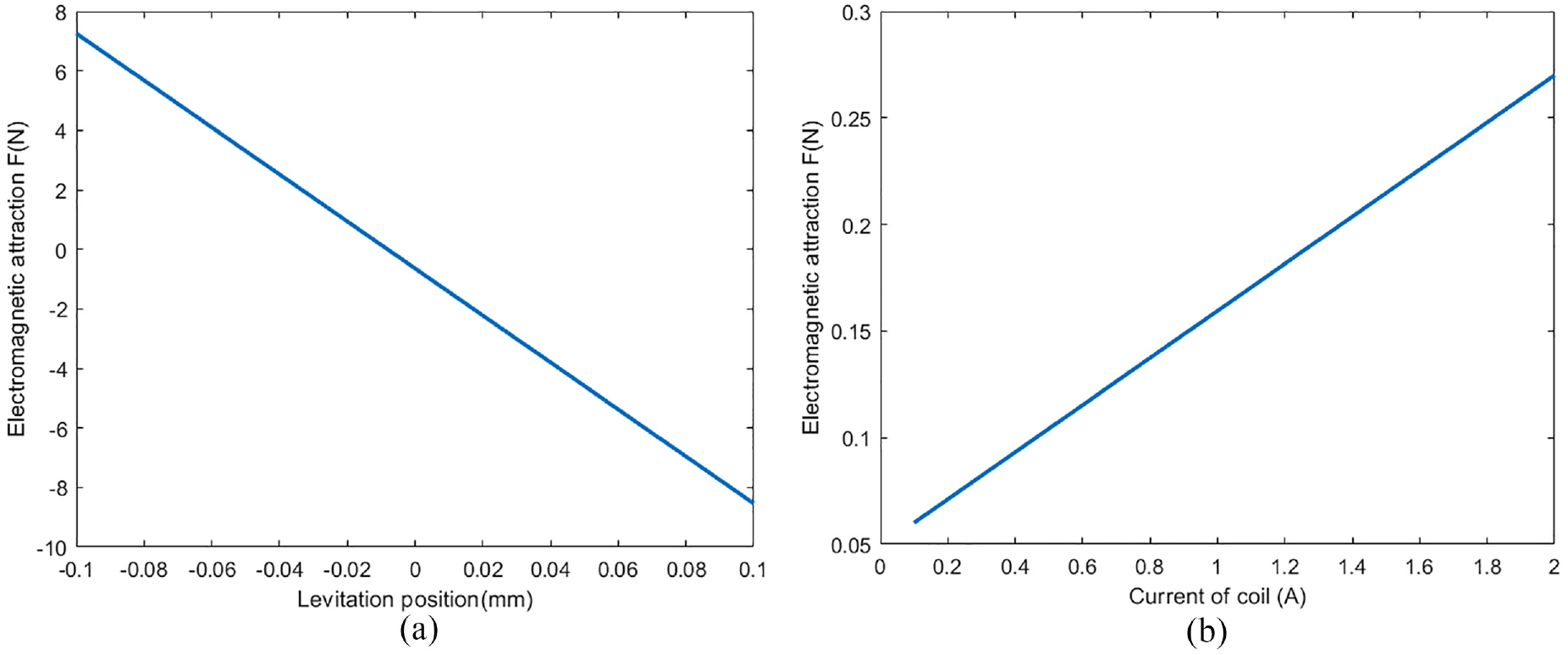
Relationship between electromagnetic attraction and levitation position and current of coil: (a) levitation position and electromagnetic attraction and (b) current of levitation control coils and electromagnetic attraction.
It is assumed that the mover core was levitated at the center height, and the upward and downward electromagnetic attraction are equal. At this time, the levitation force on the mover core can be set to zero, and the number of turns of the levitation control coil was assumed to be one. Therefore, the relationship curve between current of levitation control coil and electromagnetic attraction was obtained through simulation experiment, as shown in Figure 13(b).
Figure 13 shows that when the mover core changes in a small range in the middle of upper U-shaped stator yokes and lower U-shaped stator yokes, the levitation position and electromagnetic attraction can be approximately linear; when the current of levitation control coil changes in a small range, the relationship between the current of levitation control coil and electromagnetic attraction can also be approximately linear.
According to the above relationship curve, it can be estimated that the ratio KZ of electromagnetic attraction on the left end of the mover core to the levitation position is about 7.9 N/m × 104 N/m. The ratio KI of electromagnetic attraction on the left end to the current of levitation control coil is about 0.12 N/A. Based on the above parameters, the number of turns of levitation control coil can be roughly calculated.
Firstly, Estimation of turns of levitation control coil is introduced.
The levitation control coil converts electrical energy into magnetic energy and generates magnetic fluxes. Magnetic fluxes from levitation control coils and magnetic fluxes from permanent magnets converge in the air gap between the mover core and the U-shaped stator yokes. Therefore, the change of the current of levitation control coils can cause the change of magnetic fluxes in air gap, so as to adjust the magnetic bias level, thereby changing the magnetic energy between the air gaps, and finally adjusting the force on the mover core.
Under static conditions, the total load is determined by the sum of the mass of the mover core and the external load. Here, the mass of mover core is 1.83 kg, and the external load can be ignored, assuming that its value is zero. At start-up, the additional initial levitation force is related to the stiffness of the electromagnetic attraction in air gap and lengths of air gap. The stiffness of electromagnetic attraction is equal to the ratio of electromagnetic attraction to levitation position.
Under dynamic conditions, the interference force and dynamic load on the mover core were assumed to be ignored in the simplified calculation. The position deviation caused by the vibration of the support platform can be converted into the initial levitation force, but can be ignored in the simple calculation. If the mover core is moved from the midpoint of air gap by LQ = 0.1 mm, a 66AT levitation control coil is required. In addition, each support point is required to raise at least 1/2 of the mass of mover core, requiring a 63AT levitation control coil, so levitation control coils at the left and right ends are required to have at least 129AT. If the current entering the levitation control coil is 2.8 A, it is OK to wind 47 turns of levitation control coil. In consideration of retaining some load capacity, 55 turns of levitation control coil at left and right ends was selected.
Therefore, levitation control coils adopted multi-core soft copper wire with a diameter of 0.62 mm, which can pass 2.8 A current. The number of turns of levitation control coils on the left and right sides was 55, and the current of the two coils was controlled by DCDC converter. The self inductance on the left and right levitation control coils is about 2 mH.
Next, horizontal control coil winding mode is introduced.
The linear thrust required by the mover core is generated after the horizontal control coil is energized. For the magnetic levitation ruler designed in this paper, there are two winding methods for the horizontal control coil, the “moving armature” type wound on the mover core and the “moving iron” type wound on the “long arm” of the U-shaped stator yoke, as shown in Figure 14(a) and (b).
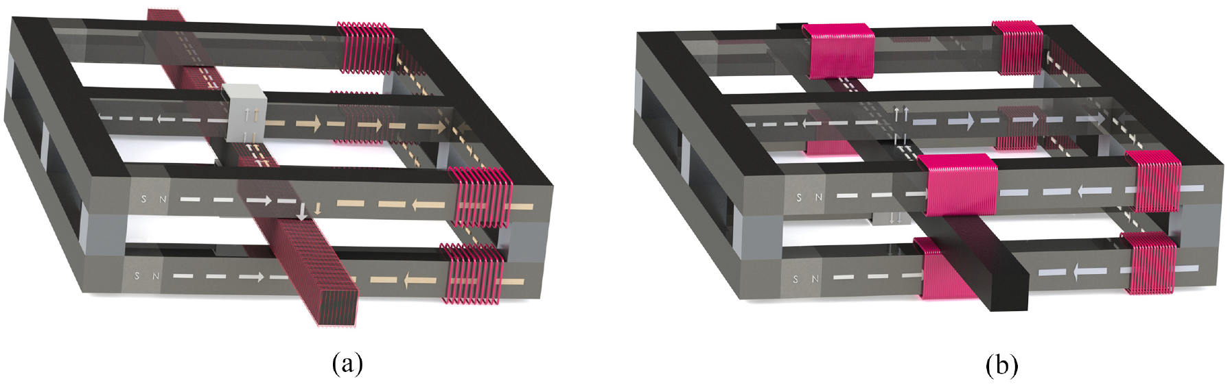
Winding method of horizontal control coil: (a) “moving armature” type and (b) “moving iron” type.
The research shows that the “moving armature” type has high energy conversion efficiency, less coil turns, less coupling, and easy control, so the “moving armature” winding mode was selected in this paper.
The size of the horizontal control coil shall adapt to the installation space provided by the magnetic levitation ruler; the maximum allowable current of the horizontal control coil shall also match with the DC converter, so that the horizontal control coil can generate the maximum thrust.
In order to calculate the horizontal thrust of the magnetic levitation ruler, the Ampere force formula is quoted in this paper. During the calculation, stray magnetic flux can be ignored, and the magnetic induction intensity B between air gaps was assumed to be about 0.6 T. A layer of horizontal control coil was wound on the mover core between air gap at the left and right ends. The number of turns of the horizontal control coil at the cross air gap between the mover core and the U-shaped stator yokes was 30. The horizontal control coil was wound by multi-core copper wires with an outer diameter of 0.7 mm, and the maximum allowable current it passes is 3.8 A. According to the ampere force formula, the maximum thrust of the horizontal control coil is about 1.37 N, so that the maximum acceleration of the mover core with a mass of 1.83 kg in the x direction is 0.78 m/s2.
Finite element analysis of magnetic characteristics of magnetic levitation ruler
Relationship between electromagnetic attraction and current of levitation control coil and turns of levitation control coil
In order to find out the relationship between the electromagnetic attraction on the mover core and the current of levitation control coil i, and the relationship between the electromagnetic attraction on the mover core and the turns of levitation control coil n, first placed the mover core in the middle of the upper U-shaped stator yokes and lower U-shaped stator yokes, that is, lengths of the upper air gap of the mover core is equal to lengths of the lower air gap.
Therefore, the levitation force on the mover core is zero. The number of turns n of levitation control coil can be adjusted within the range of 30–300 turns. The current i can be adjusted from 0.5 to 0.8 A. Through the finite element analysis, the electromagnetic attraction to the mover core was obtained, and the relationship between the turns of levitation control coil, current of levitation control coil, and electromagnetic attraction was analyzed, as shown in Table 2, the units of variables in the table are as follows: turns n – (n), current i – (A), electromagnetic attraction F – (N).
Modal analysis results of mover core.
The relationship curve between electromagnetic attraction and the number of turns and current of levitation control coil was obtained, as shown in Figure 15.
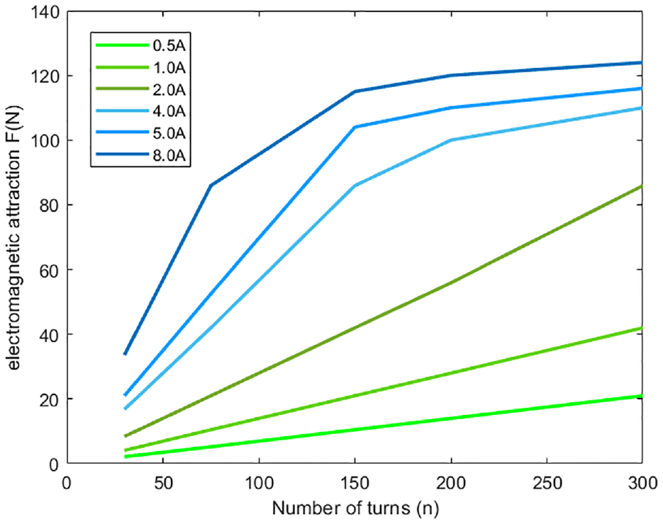
Relationship curve between electromagnetic attraction and current and number of turns of levitation control coil.
Figure 15 shows that when the current value of the coil is within a certain range, the electromagnetic attraction of the mover core has an approximate linear relationship with the number of turns of the levitation control coil. When the current value of the levitation control coil is greater than a certain value, and the number of turns is small, the number of turns and the electromagnetic attraction of the mover core increase linearly. However, when the number of turns is greater than a certain value, the number of turns and the electromagnetic attraction of the mover core stop increasing linearly, which may be caused by the saturation or demagnetization of the magnetic circuit of the mover core and U-shaped stator yoke.
In this paper, the magnetostatic field finite element method was used for further analysis. At different ampere turns of current, the magnetic force distribution along the left end of the mover core and the U-shaped stator yoke was obtained, as shown in Figure 16.
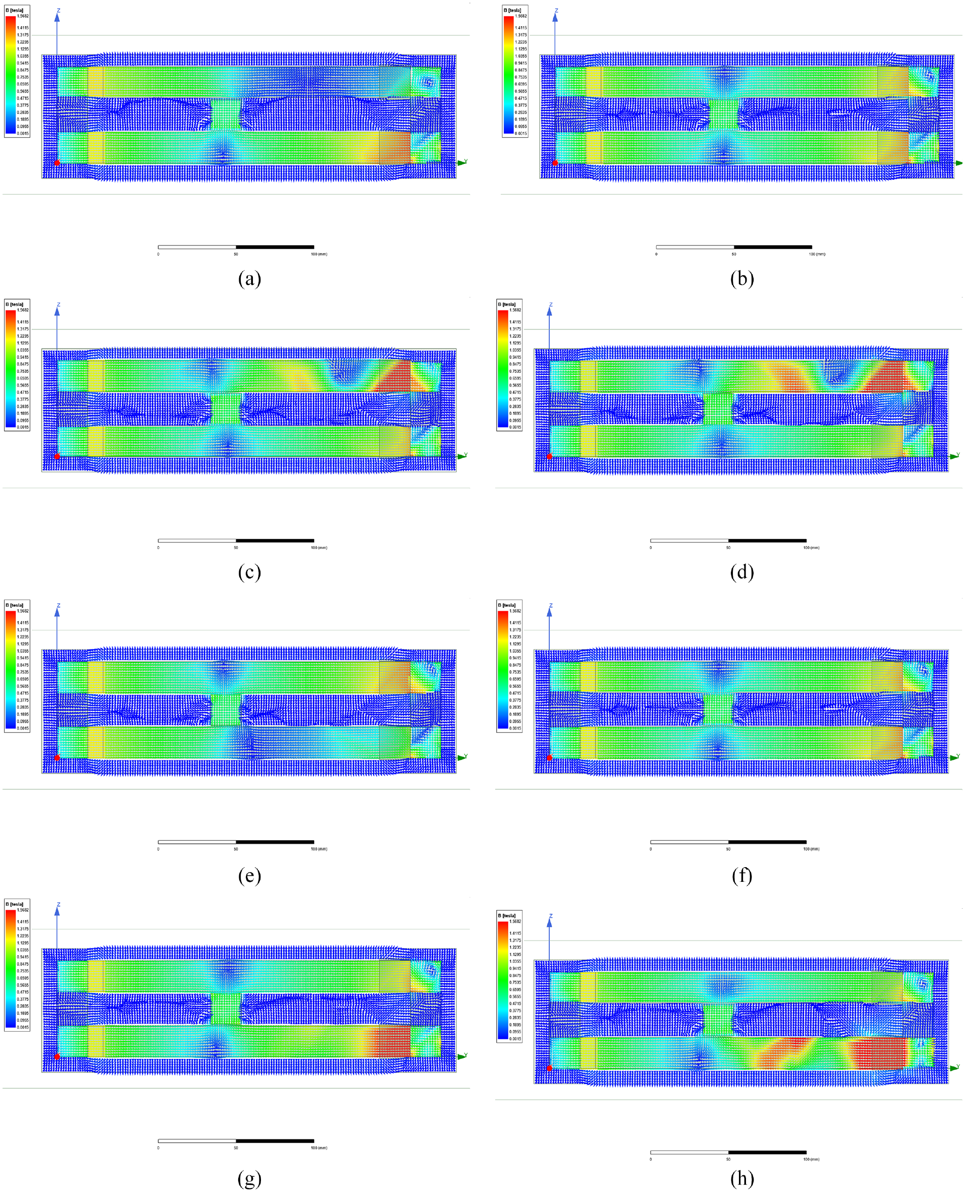
Relationship between ampere-turns and distribution of magnetic field lines of mover core: (a) up 1600AT down 1100AT, (b) up 2300AT down 1100AT, (c) up 3000AT down 1100AT, (d) up 6000AT down 1100AT, (e) up 2300AT down 800AT, (f) up 2300AT down 1100AT, (g) up 2300AT down 1400AT, and (h) up 2300AT down 6000AT.
Figure 16 shows that when the ampere-turns of the two levitation control coils on the lower side was constant at 1100AT, magnetic fluxes entering from upper air gap gradually increased with the ampere-turns of the two levitation control coils on the upper side was increasing, while magnetic fluxes entering from lower air gap didn’t change. If the ampere-turns of the two levitation control coils on the upper side were too large, it was assumed that the ampere-turns at this time were 6000AT. Due to the occurrence of magnetic saturation, the magnetic induction intensity at 6000AT did not change much compared with that at 3000AT. When the ampere-turns of the two levitation control coils on the upper side was constant at 2300AT, magnetic fluxes entered from lower air gap gradually increased with the ampere-turns of the two levitation control coils on the lower side was increasing, while magnetic fluxes entered from the upper air gap didn’t change. If the ampere-turns of the two levitation control coils on the lower side were too large, it was assumed that the ampere-turns at this time were 6000AT. Due to the occurrence of magnetic saturation, the magnetic induction intensity at 6000AT did not change much compared with that at 1400AT.
Further analyzed the relationship between the ampere-turns at the left end and the magnetic field distribution around upper air gap and lower air gap, and obtained the air gap magnetic induction intensity scalar diagram, as shown in Figure 17.
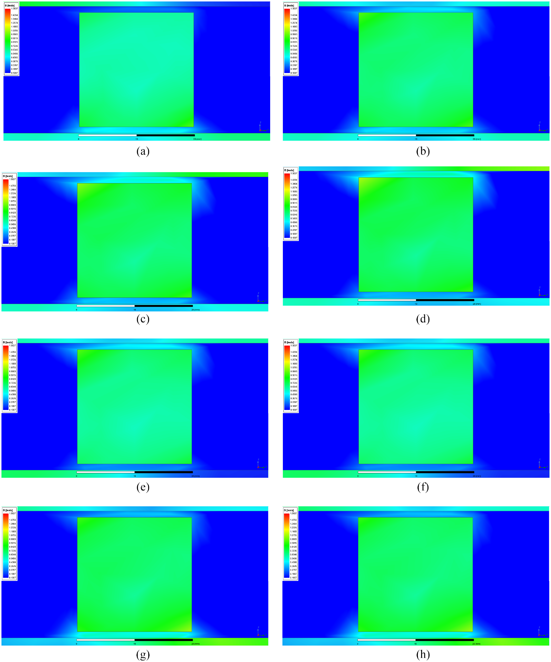
Relationship between ampere-turns and magnetic field distribution: (a) up 1600AT down 1100AT, (b) up 2300AT down 1100AT, (c) up 3000AT down 1100AT, (d) up 6000AT down 1100AT, (e) up 2300AT down 800AT, (f) up 2300AT down 1100AT, (g) up 2300AT down 1400AT, and (h) up 2300AT down 6000AT.
Figure 17 shows that when the ampere-turns of the upper coils were 2300AT and the ampere-turns of the lower coils were 1100AT, the magnetic induction intensity in upper air gap and lower air gap was symmetrical, and the sum of upper electromagnetic attraction and lower electromagnetic attraction and the gravity on the mover core was close to zero; if the ampere-turns of the coils were not the above values, upper air gap and lower air gap would gradually appear asymmetric, and upper electromagnetic attraction and lower electromagnetic attraction on the mover core would no longer balance with the gravity, and the electromagnetic attraction is related to the ampere-turns of the levitation coil; however, the magnetic induction intensity of upper air gap and lower air gap of the mover core was obviously asymmetric when the ampere-turns of the coil continues to increased; if the ampere-turns of the coil increased again, the magnetic induction intensity of air gap would not change. It can be inferred that the mover core had reached magnetic saturation at this time, and the electromagnetic attraction on the mover core was basically unchanged, which just confirms the relationship between the electromagnetic attraction shown in Figure 15 and the ampere-turns of the levitation control coil.
Relationship between plane positions of mover core and levitation force
When the mover core is in four different plane positions, the levitation force at the left end of the mover core is calculated through finite element analysis, so as to explain the relationship between the different plane positions of the mover core and the levitation force. The four plane positions of the mover core are shown in Figure 18.
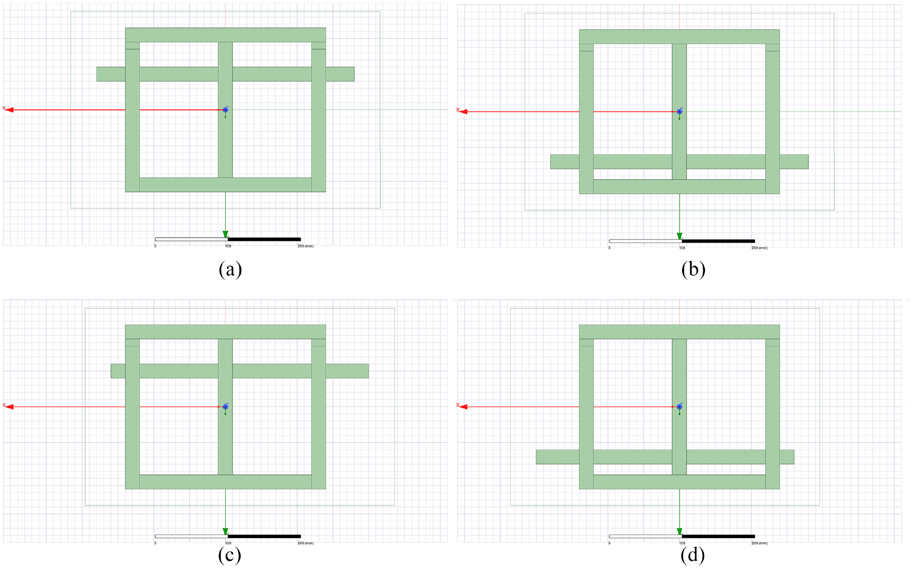
Four plane positions: (a) front position, (b) back position, (c) right front position, and (d) left rear position.
The center height of air gap of the mover core was at the position where lengths of upper air gap and lower air gap were 1.1 mm, the unit offset was 0.1 mm, and it moved upward within the range of 0–1.05 mm. The relationship between the plane position of the mover core and the levitation force was obtained through the magneto static finite element analysis, as shown in Figure 19.
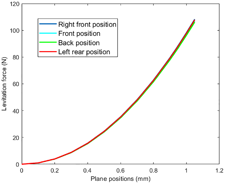
Relationship between the plane position of mover core and the levitation force.
According to the above analysis, in different plane positions, if the mover core deviates at the levitation center, the levitation force and the offset height are nonlinear, and the larger the offset is, the faster the levitation force increases.
The levitation force of the mover core at each plane position is not exactly the same. Even if the levitation height deviates an equal height upward, the levitation force on the mover core is not equal. Among them, the mover core is close to the permanent magnet in the horizontal direction, and the levitation force is large. This is because when the horizontal position of the mover core changes, the length of the magnetic circuit also changes, so the magnetic field of air gap changes, and the levitation force also changes, with a change rate of less than 3%. After the simulation experiment, the results show that the right end also meets this relationship. It can be seen that the horizontal displacement of the mover core is coupled with the levitation force, and the levitation force is related to the plane position of the mover core. When controlling the horizontal movement of the mover core, this coupling effect should be considered.
Modal analysis of mover core
Magnetic levitation ruler is a complex and precise active measurement system, and it is also a precise motor system. When the interference force of the system will cause the mover core to resonate, the interference force comes from external excitation or its own power. Through the modal analysis of the mover core, the natural frequency and vibration mode of its structure can be determined to prevent the occurrence of resonance, which is conducive to the research on dynamic response prediction of the mover core, vibration, and noise control.
The moving iron core of the magnetic levitation ruler is made of pure iron (the material property of pure iron DT4 is obtained from Volume 2 Iron and Steel Materials Engineering (Part 1) of the China Materials Engineering Code), and its structural dimensions are shown in Figure 19. Based on this, a finite element analysis model is established, and modal analysis is carried out using ANSYS 2020R2. During the work of the magnetic levitation ruler, the moving iron core is in a suspended position and does not have direct contact with other objects. Therefore, it can be regarded as a free mode, The modal frequency of the first six orders is zero, and the seventh order is regarded as the first order.
The mover core of the magnetic levitation ruler is made of pure iron (the material property of pure iron DT4 was obtained from Volume 2 Iron and Steel Materials Engineering (Part 1) of the China Materials Engineering Code), and its structural dimensions were shown in Figure 19. Based on this, a finite element analysis model was established, and modal analysis was carried out using ANSYS 2020R2. During the work of the magnetic levitation ruler, the mover core was in a levitated position and did not have direct contact with other objects. Therefore, it can be regarded as a free mode, The modal frequency of the first six orders is zero, and the seventh order is regarded as the first order.
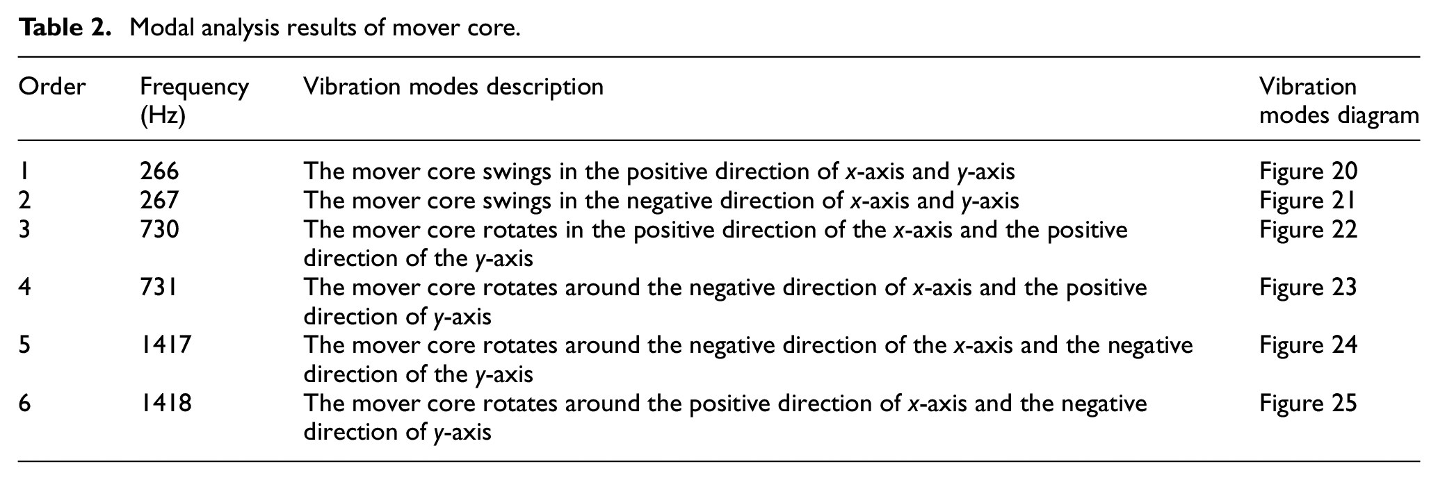
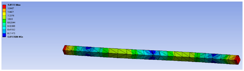
After the structure was simplified, it was imported into the software for grid division and constraint, and the following first to sixth order natural frequencies and their corresponding vibration modes were obtained, as shown in Table 2. The corresponding mode shapes of natural frequencies of each order are shown in Figures 20 to 25.
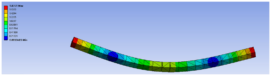
Corresponding to first order natural frequency.
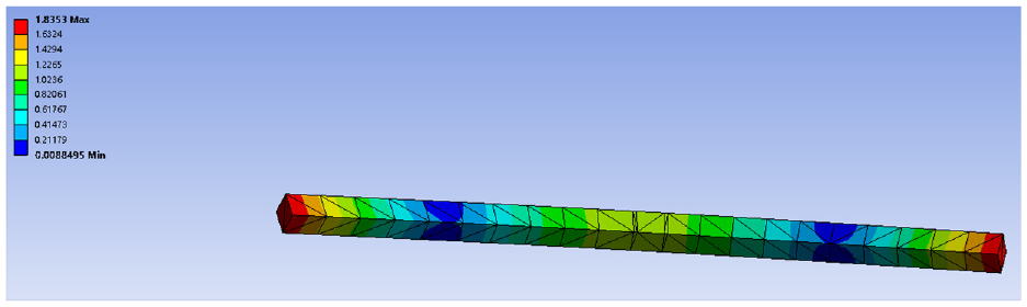
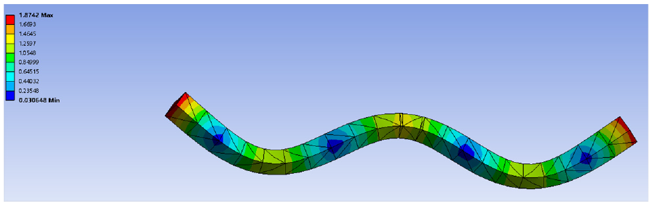
Corresponding to second order natural frequency.
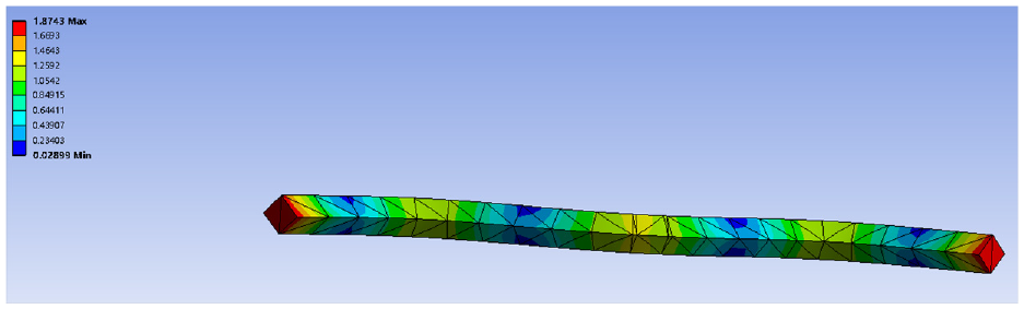
Corresponding to third order natural frequency.
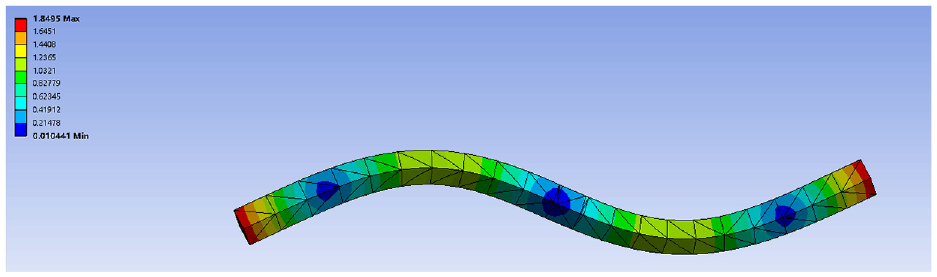
Corresponding to fourth order natural frequency.
Corresponding to fifth order natural frequency.
Corresponding to sixth order natural frequency.
It can be seen from the analysis that the natural frequencies of the first few steps are large, which indicates that the magnetic levitation ruler, a non-contact support driving mode, has high dynamic stiffness and high structural specific stiffness.
Conclusions
This paper presents a magnetic levitation ruler system based on magnetic levitation mode, designed the magnetic circuit and structure of the system, and analyzed the characteristics of the magnetic levitation ruler system. According to the working principle of the linear motor and the grating ruler, the structure of the magnetic levitation ruler was established, and eight magnetic circuits were formed, which are used to realize the stable levitation of the mover core of the magnetic levitation ruler and the relatively stable horizontal movement, thus realizing two functions of independent displacement and displacement measurement on one device. In this paper, the structural materials and their parameters, as well as the levitation and horizontal movement principle of the mover core were determined by theoretical analysis and finite element analysis. The simulation experiment shows that when the ampere-turns of the levitation control coil is less than a certain value, the electromagnetic attraction is proportional to the current passing through the levitation control coil. The levitation force on the mover core at different plane positions of the magnetic levitation ruler will change, but the rate of change is not large, that is, the magnetic field passing through the polar at different plane positions changes little, which indicates that the thrust of the horizontal control coil is less interfered by the magnetic field. The magnetic levitation ruler designed in this paper has stable magnetic field and strong controllability, which can improve the detection accuracy of CMM.
Footnotes
Declaration of conflicting interests
The author(s) declared no potential conflicts of interest with respect to the research, authorship, and/or publication of this article.
Funding
The author(s) disclosed receipt of the following financial support for the research, authorship, and/or publication of this article: This work was supported by General Program of Chongqing Natural Science Foundation (Grant CSTB2022NSCQ-MSX1350), and National Key Research and Development Project (Grant 2019YFB1707505), and Jilin Provincial Science and Technology Department Project (Grant YDZJ202303CGZH001), Project leader and corresponding author Zhenxiong Zhou, and Youth Fund of Changchun University of Technology (Grant XQNJJ-2019-02), and Jilin Provincial Science and Technology Development Plan Project (Grant 20200404211YY).
Data availability
The data used to support the findings of this study are available from the corresponding author upon request.