
Abstract
Micro terminals are often used in every laptop, mobile, and other electrical product. It is challenging to automatically buckle the terminal head to its terminal base during manufacturing because of trouble in accurate positioning and gripping. A double-robots collaborative assembly system is developed to buckle millimeter-scale terminals in three-dimensional space. Robot 1 takes the terminal head horizontally by grasping its flexible line with a customized clamp, including two fingers. Robot 2 presses the aligned terminal head through a force control strategy to ensure that the terminal head and the terminal base can complete buckling accurately, even if there is a certain deviation in the vertical direction. There are two cameras to be used in the system. A horizontally placed camera is used to detect and calculate the angle between the terminal head and the horizontal plane. The angle data will drive robot 1 to make the terminal end face parallel to the horizontal plane to complete the pose correction of the terminal head. Another camera is vertically fixed at the end of industrial robot 1 and used to detect and calculate the position deviation between the terminal head and the terminal base. The position deviation will drive robot 1 to align the terminal head with the terminal base to complete the position correction. The YOLOv3, least square, and feature extraction algorithms are used in image processing. The accuracy of the YOLOv3 target detection model trained by self-made data set can reach more than 95% under different conditions. The detection period is within 65 ms. The experimental results show that the terminal assembly system designed in this paper has excellent reliability and assembly success rate. It also has a significant reference value for other terminals’ automatic buckling assemblies.
Introduction
The use of mobile phones, pads, laptops, and other products is becoming more and more popular. These products include many terminal buckling operations in the assembly process, such as power terminals, antenna terminals, flexible printed circuit terminals, and so on. 1 With the development of electronic products toward light and thin, the scale of terminals is becoming smaller, which puts forward a more serious difficulty for automatic assembly. One terminal typically includes a terminal head with a flexible line and a terminal base mounted on the printed circuit board. The primary size of many terminals used in 3C electronic products is only 1 mm or so (such as terminals of radio frequency lines in mobile). They are not a particle but have a pose. The position and pose of the terminal heads must be accurately aligned with the terminal base simultaneously before buckling. How to grasp the terminals is also a considerable difficulty. In order to realize automatic buckling between the terminal head and base, a machine tool should be prepared to grip the terminal head. Because the terminal head has the characteristics of irregular shape, easy damage, and easy to be covered by tools, it is not convenient to grasp such a small terminal head directly with machine tools. An alternative way is to grip the line closing to the terminal head. But the pose of the terminal head will not be locked because of line flexibility, and the pose of the terminal head should be recognized by a sensor. 2 The terminal buckling needs not only accurate alignment but also needs moderate buckling force. Excessive buckling force will damage the components, and too small force will make buckling fail. At present, it is still dominated by manual operation, with low operation efficiency and high skill requirements for operators. How to realize automatic buckling of micro terminals is an urgent problem to be solved in the assembly of electronic products.
3-D assembly is typically realized using one 6-DOF industrial robot because a component’s position and pose (total 6-DOF) can be adjusted from the 6-DOF of a robot. Compared with a single robot, double even multi-robot cooperation is more flexible and can complete more complex work in 3-D space. 3 Machine vision is frequently used to position a component to be gripped accurately.4–7 With the development of image processing, significant improvements have taken place in the manufacturing industry.8–11 Wang et al. 12 proposed a novel rail-guided multi-microrobotic system for the assembly of cellular structures. Song et al. 13 presented an intelligent robotic assembly system for screen components. Yang et al. 14 designed a workpiece assembly system based on machine vision to overcome the difficulty of the manual clamp. These assembly systems use monocular vision to detect the position of components. However, using monocular vision cannot measure the position and spatial pose of components at the same time. To solve this problem, many researchers apply multi-vision to the field of automatic assembly. Yan et al. 15 developed a robotic assembly system to assemble two components with 6-DOF in three-dimensional space based on the U-NET network and the image features. Zhang et al. 16 made a robot guided by one or more cameras to align the assembly features of small parts accurately. Wang et al. 17 proposed a multi-angle automotive fuse box detection and assembly method based on machine vision. These assembly methods use more than one camera to measure the position and posture of components. However, directly extracting component edges cannot accurately locate components in a complex assembly environment. The traditional picture processing methods are difficult to meet the assembly requirements, especially for the micro terminals with flexible lines.
Assembling force is another critical factor to affect the success of assembly. Normal industrial robots have no force signals to be used for assembly. It is more challenging to assemble vulnerable electronic components because of the need for a more accurate and smaller force. Great research progress in force control of industrial robots has been made in recent years.18–20 Some researchers have used force information to guide the assembly process. Zou et al. 21 proposed an intuitive and effective method using a sensor to guide the industrial robot to carry out the Peg-in-Hole assembly. Li et al. 22 used the micro-force to guide the contact process in assembly. However, the problem of flexibly switching the end effector from free to contact space is still not addressed. The change of contact constraint condition will easily cause system instability.
Automatic assembly systems designed using visual information only have limited capabilities.23,24 The combination of vision, force information, and multi-robot cooperation makes the design of a high-precision automated assembly system possible.25–28 The purpose of this paper is to propose a scheme of automatic assembly for micro terminals using double robots. A terminal head clamps a flexible coaxial cable. The terminal bases have been mounted on the Printed circuit board in advance. The function of this system is that the terminal head with flexible coaxial cable can be automatically picked up, calibrated with position and pose, and buckled to the terminal base. The main contributions of this paper are as follows:
The assembly system with two manipulators is developed to realize the assembly of micro terminals. A robot is used to grasp the terminal head, and the grasping position is on the line closing to the terminal head. The other robot is used for force-controlled press buckling.
Two cameras are used in the system. These two cameras do not form a binocular vision system but are separated. One camera is used to detect the rotation angle of the terminal head around the coaxial line, and the other is used to monitor the position deviation between the terminal head and the base.
A visual localization algorithm combining the YOLOv3 network model and irregular image feature contour extraction is developed to accurately measure the position and spatial pose of terminals in a complex background.
A force control strategy is proposed by combining the impedance algorithm with the force space switching algorithm. This strategy can solve the instability problem caused by the space switching of the end effector and the problem of component damage caused by excessive force during assembly.
Components and system configuration
Components
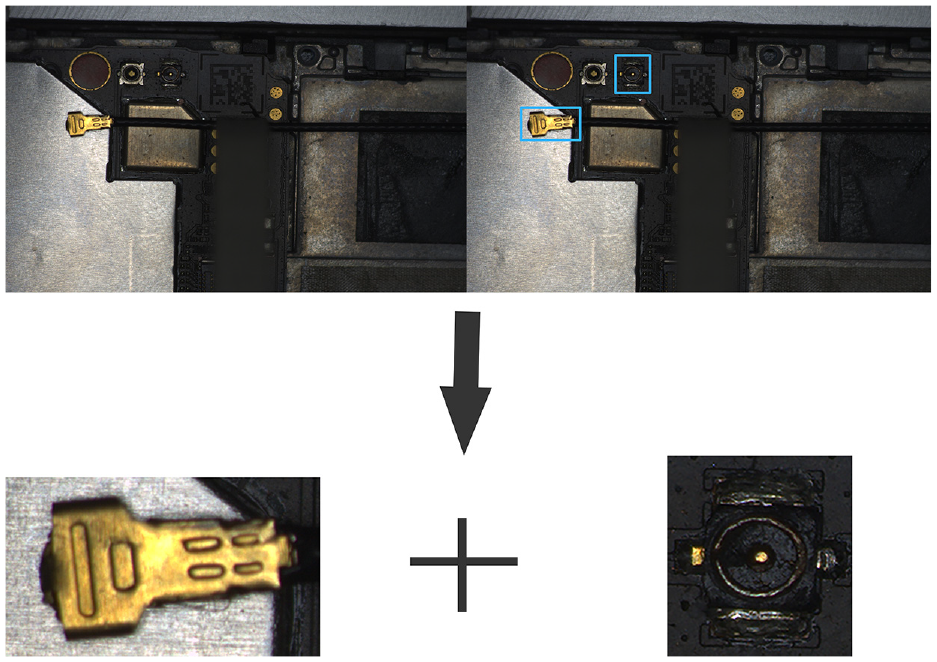
The component to be assembled is a terminal set, including a terminal head and a terminal base. The terminal head is grasped onto a flexible coaxial cable that is often called a radio frequency (RF) line, as shown in Figure 1(a). The detailed structure of the terminal head is illustrated in Figure 1(b). The RF line and its terminal heads meet the IPEX4 criterion. Its line body diameter is 0.81 mm and has a certain flexibility. The width and height of the terminal head are only 2.1 and 0.9 mm, respectively. The transverse diameter of the assembling side is only 1.82 mm, as shown in Figure 1(c). The semi-finished mobile phone to be assembled is pictured in Figure 2(a). The terminal bases on the PCBs at both ends of the mobile phone are illustrated in Figure 2(b). The dimension of a terminal base is shown in Figure 2(c). The transverse diameter of the terminal base is 1.5 mm.
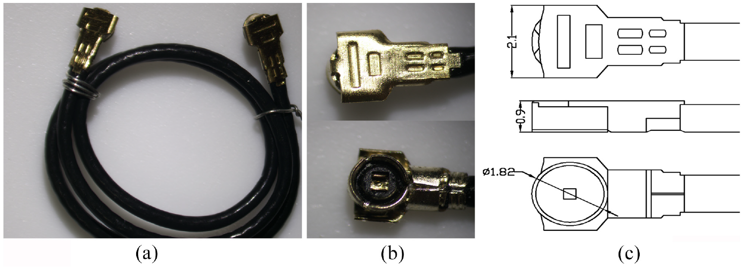
RF line diagram: (a) the RF line, (b) the terminal head, and (c) the size of the terminal head.
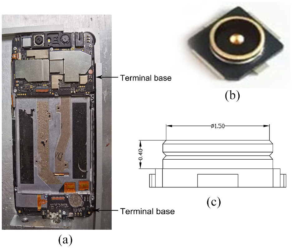
Terminal bases diagram: (a) the mobile phone with assembly, (b) the terminal bases, and (c) the size of terminal bases.
The assembly task is to buckle the terminal head with the terminal base on the mobile phone. In order to ensure that the terminal head can be successfully assembled with the terminal base, the terminal head should be horizontal to the plane of the terminal base, as shown in Figure 3(a). If the terminal heads are not parallel to the terminal bases, as shown in Figure 3(b) and (c), the buckling may fail. Therefore, it is necessary to adjust the posture of the terminal head to make it parallel to the terminal base, as shown in Figure 3(b). The schematic diagram of successful assembly is shown in Figure 3(e).
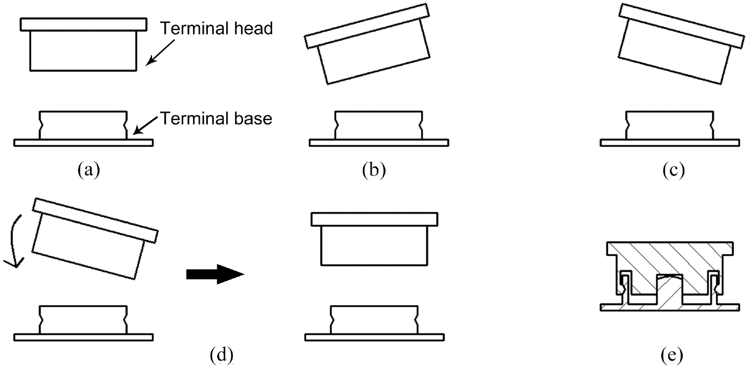
Schematic diagram of buckling: (a) the buckling assembly conditions, (b) the terminal head tilts to the left, (c) the terminal head tilts to the right, (d) adjust terminal head posture, and (e) assembly successful.
Assembling system configuration
The dimension of the terminal head is only about 2 mm in diameter and 0.9 mm in thickness. It is hard to be grasped. Even if there is an electric gripper that can directly grasp the terminal head, it will be hard to realize the calibration of the position and pose of the terminal head because it is shielded by the electric gripper and cannot be photographed by a camera. Therefore, to align the terminal heads with the terminal bases and buckle each other in 3-D space, two 6-DOF Industrial robots are required to cooperate, as shown in Figure 4. One of the two robots (Robot 1) is used to grasp the RF line (not the terminal head) and adjust the position and pose of the terminal heads. Another robot (Robot 2) is used to press the terminal head to be buckled with its terminal base. This system further allocated a predetermined holder to which the terminal head can be fitted, and the RF line is exposed out of the holder. It is very convenient for robot1 to grasp the RF line and guarantee a consistent initial pose. Since the grasping point is very close to the terminal head, the position and pose of the terminal head relative to the electric gripper will not change during the movement of robot 1. It usually is easier to grasp the RF line than the terminal head because the body of the RF line is a slim cylinder and more regular.
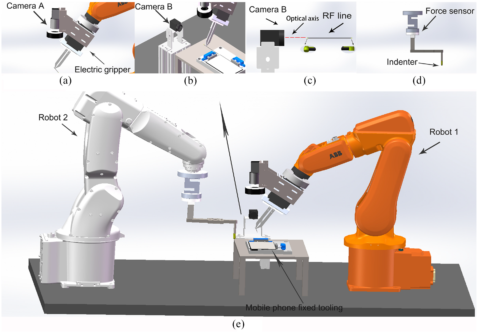
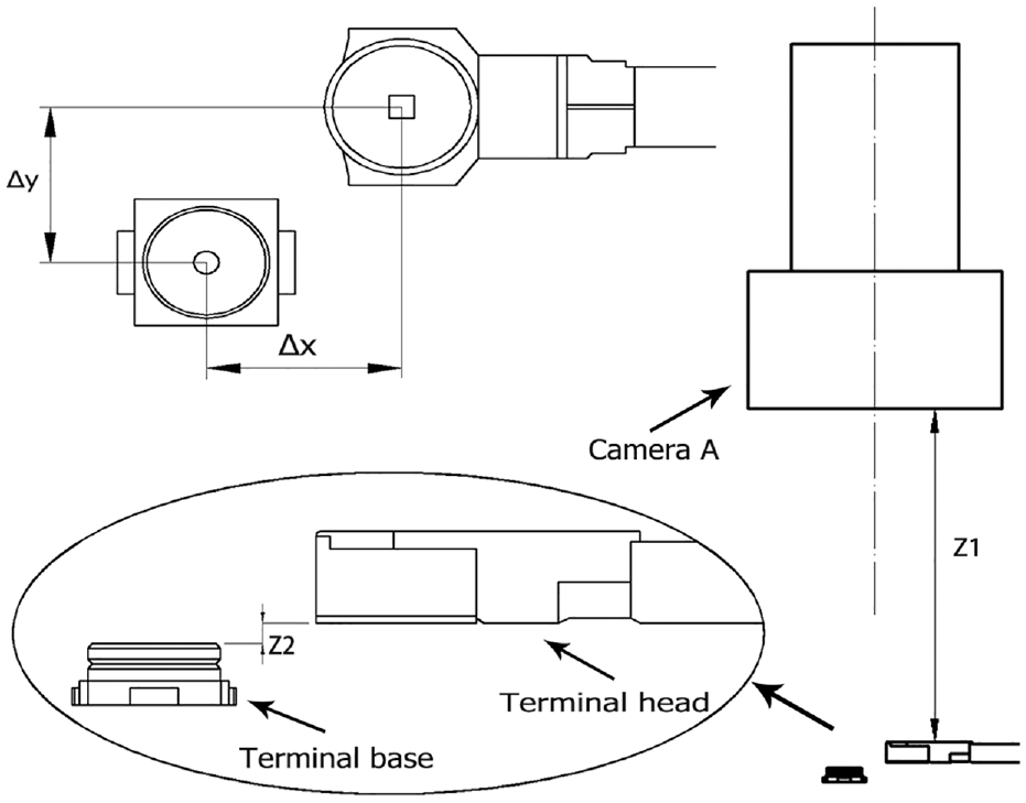
System configuration: (a) camera A and the electric gripper are mounted at the end of robot 1. Camera A is used to measure the position of terminals and terminal bases, and the electric gripper is used to grasp the RF lines, (b) camera B is used to measure the pose of terminals, (c) The optical axis of camera B needs to be parallel to the axis of the RF line, and the terminal heads are at both ends of the RF line, (d) the force sensor and pressing head are installed at the end of robot 2 to feedback force information and press terminals, and (e) automatic assembly system based on the cooperation of two robots.
As shown in Figure 4(a), the electric gripper with a customized line claw is installed at the end of robot 1 to grasp and move the terminal heads during assembly. The line claw of the electric gripper can be controlled to grasp or slightly loosen the RF line. Camera A is installed on the electric gripper of robot 1 to measure the position difference between the terminal head at the end of the RF line and the terminal base at the mobile phone. In addition, the optical axis of camera A must be orthogonal to the terminal base. It will be easily realized if the photographing posture of robot 1 is manually adjusted in advance and recorded as a predetermined posture. Another industrial camera (Camera B) is installed with its optical axis parallel to the RF line to detect the possible angle between the terminal head and base, as shown in Figure 4(b) and (c). After the terminal head and terminal base are aligned, the terminal head needs to be pressed to complete the buckling operation. Therefore, it is necessary to install an indenter on robot 2. Only using the position control of robot 2 may cause an excessive pressing force to damage components or insufficient buckling force to result in buckling failure in the event of inaccurate alignment. In order to improve the accuracy and success rate in the buckling process, a force sensor is installed on the root of the indenter, as shown in Figure 4(d). The pressing process of the indenter is controlled by force from the force sensor.
To describe the position, pose, and motion of two robots, sensors, tooling, and components, the coordinates need to be firstly established, as shown in Figure 5. As shown in Figure 5(a), the Z axes of {CA} and {CB} are the optical axis of the corresponding cameras and are perpendicular to the image planes. As shown in Figure 5(b), the image coordinate system {P} takes the center of the imaging plane as the origin. The pixel coordinate system {ca} takes the upper left corner of the imaging plane as the origin, and its coordinates are all in pixels. The region of interest (ROI) coordinate systems {H} and {B} are established on the ROI images of the terminal head and terminal base, respectively. As shown in Figure 5(c), the world coordinate {W} and the manipulation coordinate {M1} are established on robot 1. Manipulation coordinate {M2} is established on robot 2. As shown in Figure 5(d), the camera coordinates {CA} and {CB} are established on the optical center of corresponding cameras. The X and Y axes of {CA} and {CB} are along with
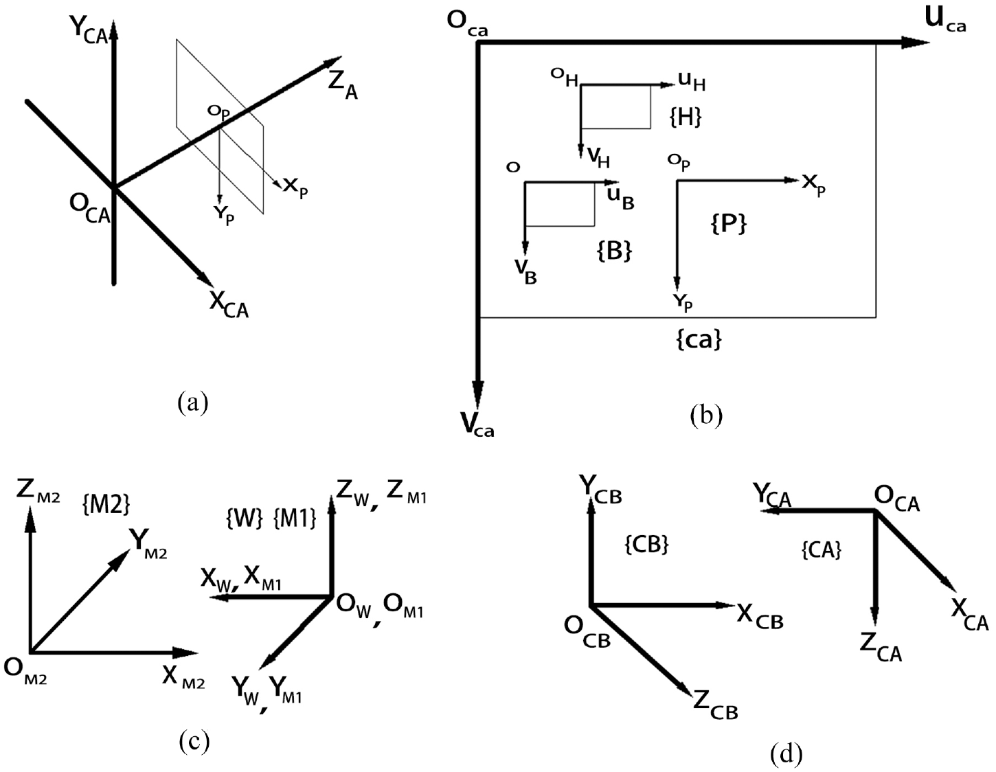
Coordinates system: (a) relationship between camera coordinate system {CA} and image coordinate system {P}, (b) image coordinate system {P}, pixel coordinate system {ca}, ROI coordinate systems {H} and {B}, (c) manipulation coordinate {M1} and manipulation coordinate {M2}. The world coordinate {W} coincides with the manipulation coordinate {M1}, and (d) the camera coordinates {CA} and {CB}.
Automatic assembly process
The assembly process of a terminal based on vision and force feedback is shown in Figure 6. Firstly, the electric gripper of robot 1 grasps and moves the RF line body so that the terminal head enters the field of view of camera B. The rotation angle

Automatic assembly process.
Schematic diagram of the transition from 3D space to 2D space.
Terminal head angle adjustment
In order to promote the accuracy of image processing, it is necessary to calibrate the two cameras to obtain the internal parameter and distortion coefficients. The calibration method of Zhang 29 is adopted in this system.
Because the grasping position is on the RF line body rather than on the terminal head, there may be a slight rotation angle
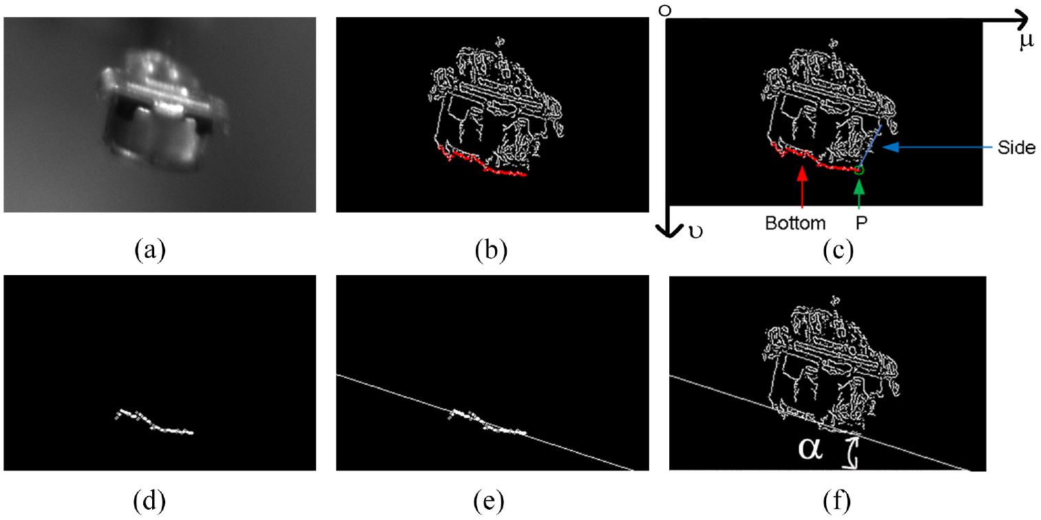
The image taken by camera B is shown in Figure 8(a). Using the target detection model trained by YOLOv3, 30 the prediction frame of the terminal head in the picture can be obtained, and the result is shown in Figure 8(b). In order to display the terminal head, enlarge Figure 8(a) as shown in Figure 8(b) and (c) as shown in Figure 8(d). After target detection, the coordinates, width, and height of the prediction frame of the terminal head can be obtained. According to the four parameters of the prediction frame, the ROI image of the prediction target can be intercepted from the original image, as shown in Figure 8(e). This step filters most of the complex background that does not need but affect the feature extraction. Only a small part of the required content is retained in the image. In order to enhance the object features in the ROI image, in this paper, image median filtering is used to smooth the image. The results after median filtering are shown in Figure 9(a). In order to accurately locate the target object, the Canny operator is used to detect the contour edge of the terminal head.
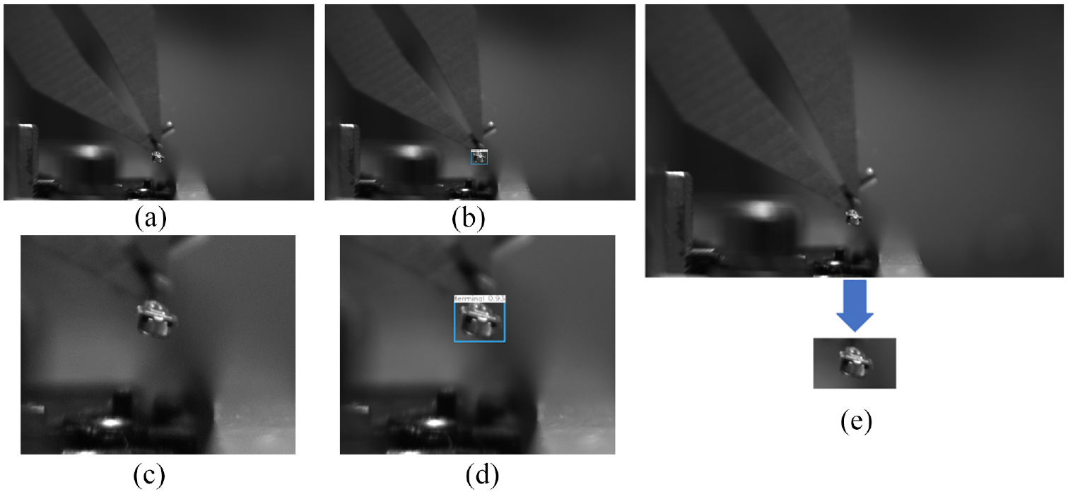
Target detection result of the terminal head: (a) the original figure was taken by camera B, (b) the result after target detection, (c) local magnification of (a), (d) local magnification of (b), and (e) the ROI image of the terminal head cut out from the original image.
Calculation steps of the rotation angle
As shown in Figure 9(b), the bottom contour needs to be extracted to calculate the rotation angle
Due to the interference of light, noise, and other factors, the bottom contour of the terminal head is discontinuous and not straight. In order to solve this problem, the least square method is used to fit the bottom edge contour of the terminal head. The rotation angle

Here the relative minimum means square error Q is used to measure the deviation between the fitted line and the input point set. The expression of the relative minimum means square error Q is in equation (2).
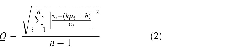
In the formula, n represents the number of points in the bottom contour point set.
The straight-line fitting result based on the least square method is shown in Figure 9(e). The fitting straight-line result is displayed in the contour of the terminal head, and the result is shown in Figure 9(f). After the rotation angle
Terminal head alignment
In order to establish the relationship between an image and actual 3-D space, it is necessary to achieve the scale of a pixel in an image equivalent to physical distance. During assembly, camera A is driven by robot 1 to a specified position to take pictures of the terminal head of the RF line and terminal base of the mobile phone. When robot 1 reaches the predetermined posture used for photographing, the optical axis of camera A is perpendicular to the plane where the terminal base is located. An image including a terminal head and a terminal base is taken, as shown in Figure 10. The target detection model trained by YOLOv3 is used to forecast the position of the terminal head and the terminal base on the image. According to the result of target detection, the ROI image of the terminal head and the ROI image of the terminal base can be further obtained. Record the ROI image center point, including the terminal head
Target detection results.
The procedure of searching and positioning the terminal head in the image is shown in Figure 11. The terminal heads of the RF lines are yellow and have a significant color difference from the background, as shown in Figure 11(a). Therefore, the terminal head can be extracted by segmenting the image in HSV color space. Since the Yellow space segmentation threshold in HSV is (34 > H > 26, S > 43, V > 46), the threshold of H, S, and V channels is set to [20, 70, 70] to [50, 255, 255]. After HSV-based image segmentation, the terminal head can be extracted from the image, as shown in Figure 11(b). Due to the complexity of the image background and noise interference, the image after segmentation still needs several steps of processing to achieve a precise position from a clean and clear terminal head contour.
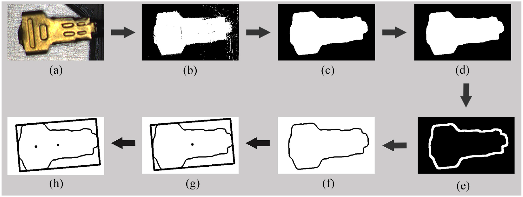
Calculation steps for the coordinates of the buckling center point of terminal head 1: (a) input image, (b) segmented image, (c) median filtered image, (d) image after closing operation, (e) image after morphological gradient processing, (f) filtered contour image, (g) minimum circumscribed rectangular centroid image, and (h) center point of buckling.
Firstly, the median filter algorithm is applied to the segmented image to reduce the noise interference, as shown in Figure 11(c). Secondly, the closing operation of image morphological processing is used to fill the holes in the image and smooth the sharped and fractured contour of terminal head 1, as shown in Figure 11(d). The closing operation dilates and erodes the image. Thirdly, the system uses morphological gradient operation to extract the smooth contour of terminal head 1, as shown in Figure 11(e).
There may be some other parts with similar colors in the background, even after the above operation, and more than one component contour may exist. Therefore, to position the terminal head, it is necessary to extract and filter its contour. Here, the contour extraction algorithm proposed by Suzuki 31 is used. After all the contours are extracted, the number of contours in the image and the point set contained in each contour can be obtained. The contour of the terminal head typically occupies most of the space in the image and is a continuous and the largest point set. By selecting the contour with the largest number of point sets, the contour of terminal head 1 can be filtered. The filtered contour is shown in Figure 11(f).
After filtering the contour of the terminal head, the centroid method is used to locate the terminal head. The centroid method locates the target by obtaining the centroid of the target object in the image, as shown in Figure 11(g). The calculation formula of centroid A of the target object is in equation (3).
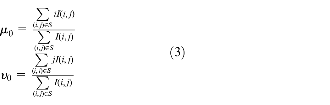
In equation (3), I (i, j) represents pixels of a binary image.
Centroid localization needs to select the internal points or contour points of the target object, which is easily affected by the edge noise points of the target object and results in the positioning accuracy being unable to meet the requirements. Moreover, due to the flexibility of the RF line body, there may be a yaw angle
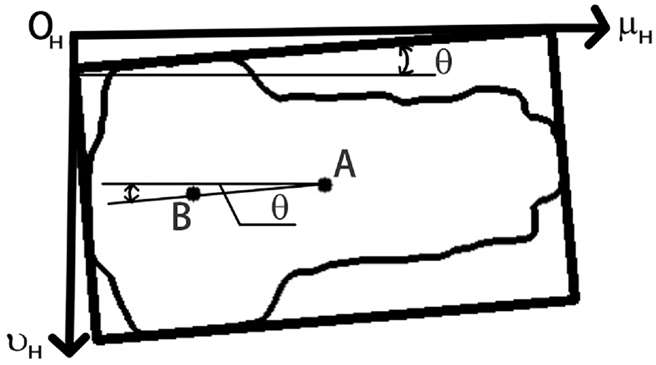
Relationship between the buckling center point and the centroid of terminal head 1.
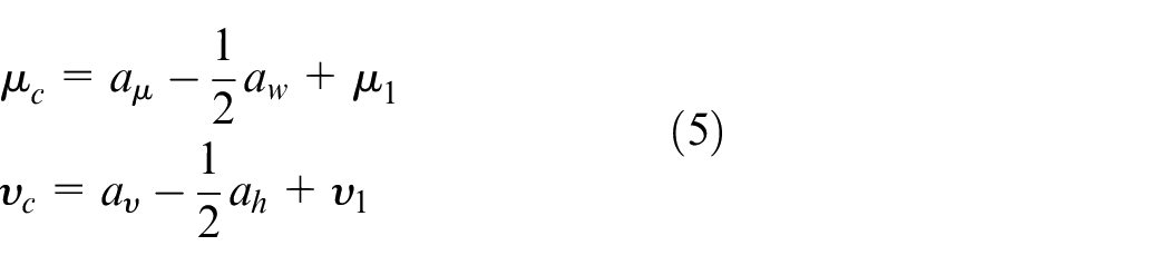
The position of the terminal head in the image can be known based on the centroid positioning of the minimum external rectangle. But to realize the assembly of two parts, it is necessary to know the coordinates of the buckling center of the terminal head, as shown in Figure 11(h). In the world coordinate system {W}, the distance
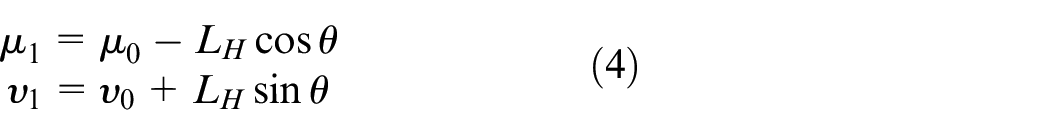
The coordinate calculation formula of the buckling center point
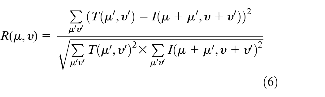
The pose of the terminal base at the mobile phone in the image is relatively fixed during assembly, which is suitable for positioning based on template matching. The matching result is shown in Figure 13. This system uses the MatchTemplate function of image processing library OpenCV to experiment and selects the normalized square difference matching method to find the target position. The matching formula is in equation (6).
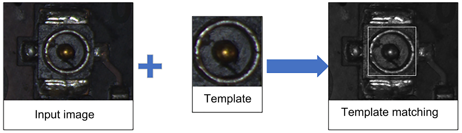
Positioning of terminal base 1 based on template matching.
In the formula,
As can be seen from equation (6), when the value of
The coordinate calculation formula of the buckling center point
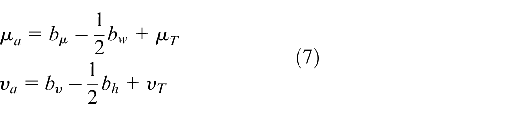
The position difference
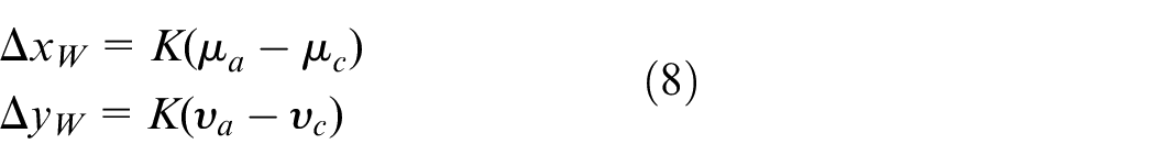
In the formula, K is the transformation coefficient from a distance in the pixel coordinate system {ca} to the distance in the world coordinate system {W}.
Pressing and buckling control based on force feedback
Force control of terminal buckling process
The force feedback will play an essential role during buckling. It is protective for the terminal and mobile phone not to be damaged in case the terminal head and terminal base are not aligned precisely or the terminal base is elevated slightly because of the discreteness of different mobile phones. Further, it can also improve the buckling success rate, in case the terminal base is descended slightly, similarly because of the discreteness of different mobile phones.
Based on the above reasons, it is necessary to use an active compliance control method to ensure the buckling force is at a relatively fixed value in the assembly process. The force sensor is installed at the wrist of robot 2, and a force control algorithm is introduced to form a closed-loop system. The buckling distance is not present in the buckling process, but the expected buckling force is set to make robot 2 move with this force as the target. Even if there is an alignment error, the assembly force can be within the allowable range to ensure the safety of components.
The impedance control 32 + position compensation algorithm is used to realize active compliance in the pressing stage. When there is a deviation between the actual position of the indenter and its expected position, there will be a force deviation between the environmental contact force and the expected force. The position and force deviations are used to establish the impedance model in equation (9).

In equation (9),
The expression of the impedance model is continuous, while robots and computers are discrete-time systems, so it is necessary to discretize the impedance model further. The discretization of the impedance model formula is given in equations (10)–(12).
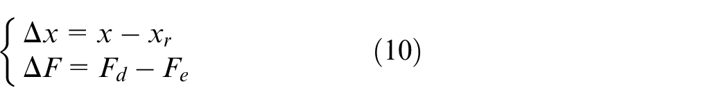

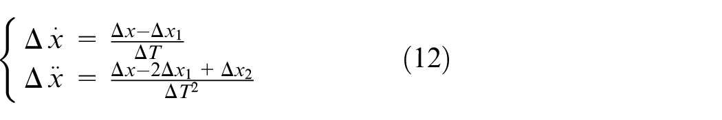
In equation (12),
Substitute equation (12) into equations (11)–(13).
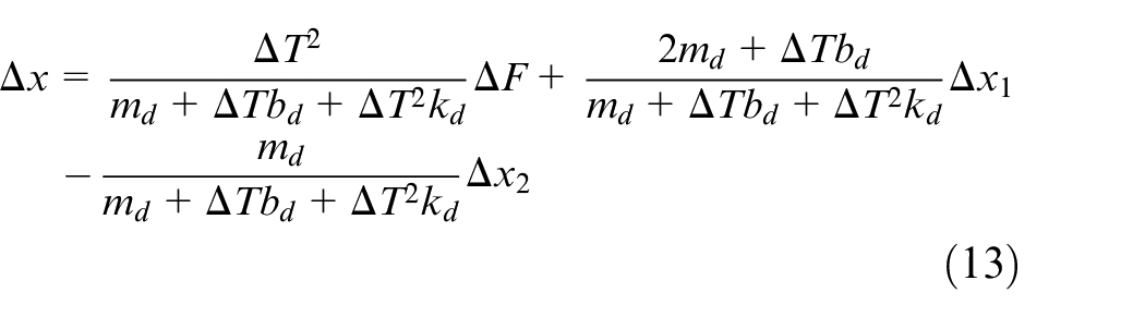
Equation (13) can be expressed as equation (15) according to equation (14).
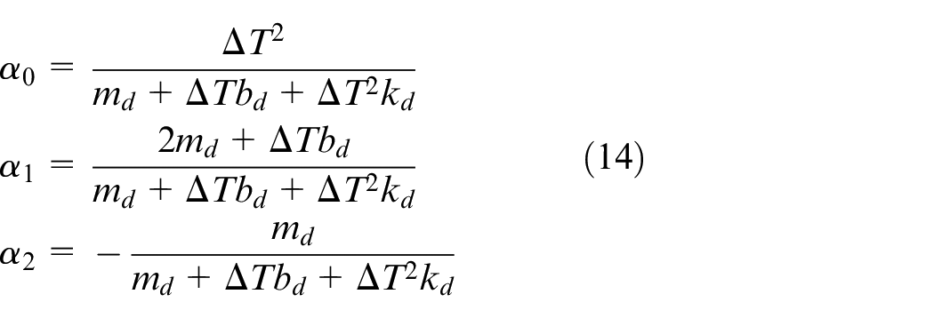

According to equation (15), the feed position compensation can be determined depending on the force deviation between the expected force and the actual contact force sampled by the sensor and the position deviation of the first two cycles.
Switching strategy from free space to contact space
The process of buckling the terminal heads onto the terminal bases will involve switching from free space to constrained space. The buckling process between terminal heads and terminal bases can be divided into two segments at the contact instant. Before contacting, the traditional position control method should be used. After contacting, the impendence as mentioned above control method will be used. When and how to switch is significant. Suppose the impedance control mode is activated before contacting. In that case, it is easy to produce a large overshoot due to the maximum deviation between the actual force and the expected force, affecting the control system’s settling time. If the force control mode is not activated on time at the moment of contact, the range of the force in the first control cycle cannot be guaranteed.
Furthermore, we can also use the displacement deviation
The switching control process from free to contact space is shown in Figure 14.
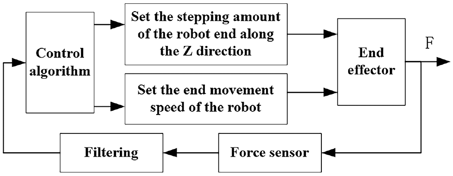
Switching control program from free space to contact space.
The switching control algorithm here adjusts the movement of the end-effector along the Z-axis according to the
The threshold value of the given contact force is
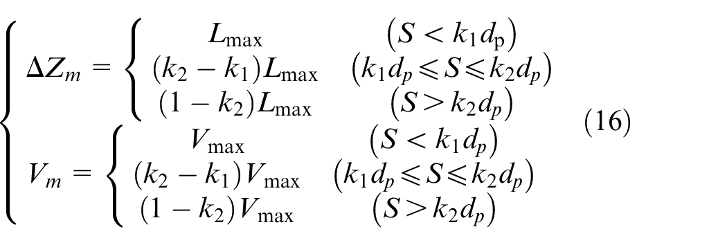
In equation (16),
The control algorithm not only limits the maximum step of the indenter and identifies the contact between the terminal heads and terminal bases at the first moment but also limits its contact speed. In this way, the collision force between the two components is not too large, and the stability of the switching transition is ensured.
Experiment
Experimental system
According to the scheme of Section 2.2, an experimental system is established, as shown in Figure 15. Both cameras in this system are CMOS photosensitive and have a resolution of 3072 × 2048. Every pixel size is 2.4 μm × 2.4 μm. Camera A is a color camera, and camera B is a black-and-white camera. Each camera is equipped with a ZX-SF3520C lens with a focal length of 35 mm. The camera light sources adopt ZX-LA7330 annular LED light. The illumination angle of the light source is 30°, which has the characteristics of uniform illumination and no shadow in the image. Robot 1 is ABB Robot IRB120 and robot 2 is Xinshida robot SD7. In this experiment, the force sensor JLBS-10KG is installed on robot 2. The collected force signal is converted from analog to digital, and the digital data is filtered through the TDA-04 digital transmitter. Then, it is conveyed to the main computer through RS485 serial port communication. The measurement range of the force sensing system is ±100N, and the resolution of the force along the Z direction is 0.1N.
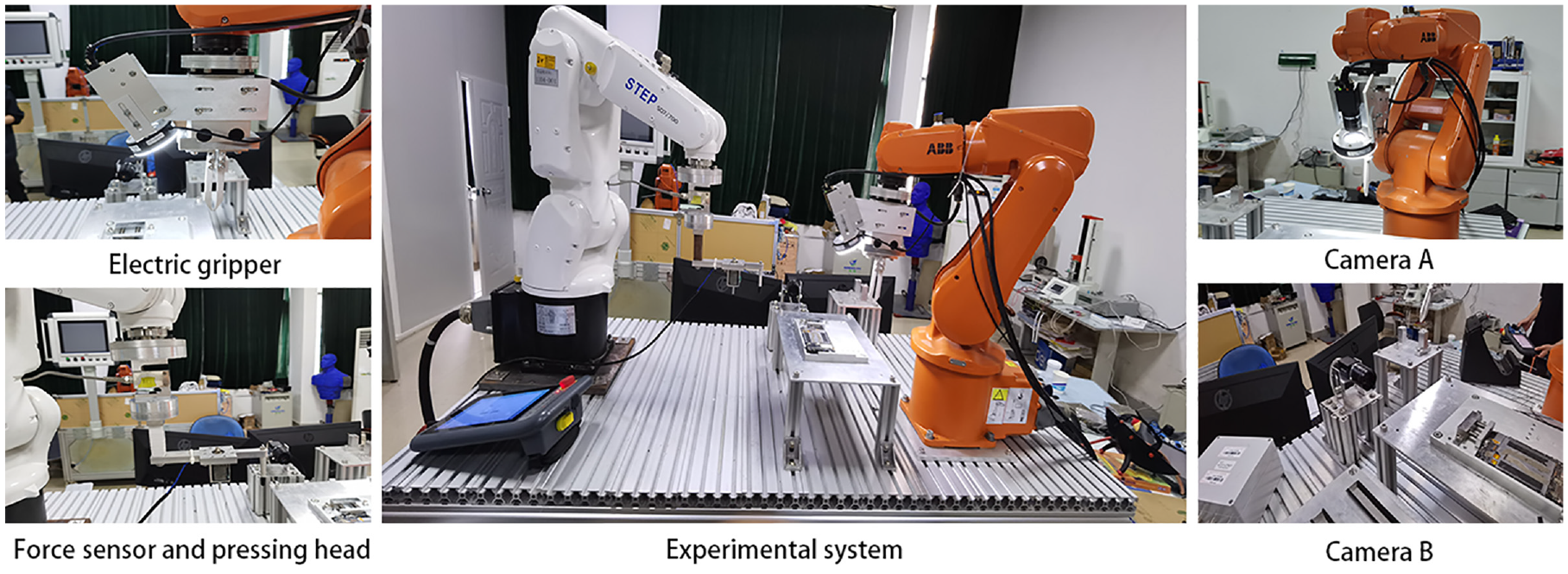
Experimental system.
Accuracy of the target detection algorithm
Object detection model based on deep learning requires many image samples for training and often requires self-made data sets for specific goals that are generally unavailable. To obtain the required data sets, a large number of photographs need to be taken with camera A and camera B and then labeled with open source software Labeling. A total of 500 images were sampled, 10% of which were used for testing and 90% of which were used for training. This paper takes another 100 pictures of terminal heads and terminal bases to test the detection effect. The results show that under normal lighting conditions, the detection accuracy of this model for terminal heads and terminal bases is more than 99%. Under other complex conditions (relative intense or dark light, background change), the detection accuracy can also reach more than 95%. At the same time, this paper uses RTX2080 GPU to accelerate the detection algorithm. Under the input image of 3072 * 2048, the detection time is about 65 ms.
Test of image feature extraction algorithm
The rotation angle calculation algorithm of the terminal head proposed in Section 3 is named algorithm A1. The alignment algorithm proposed in Section 4 is named algorithm A2. This experiment will test and verify the two algorithms from three aspects: stability, rapidity, and accuracy.
In order to test the stability of the algorithms, the two algorithms are arranged to be tested 80 times to obtain the repeated positioning accuracy of each algorithm. The specific experimental results are shown in Table 1. As can be seen from Table 1, the repeated measurement accuracy of algorithm A1 is 3.73°, which can meet the repeated measurement accuracy requirements of the system. The maximum repeated positioning accuracy of algorithm A2 is 1.81 pixels. The pixel equivalent is 0.0124mm. The algorithm A2 is stable and also meets the repeated positioning accuracy requirements of the system.
Test results of image feature extraction algorithm.
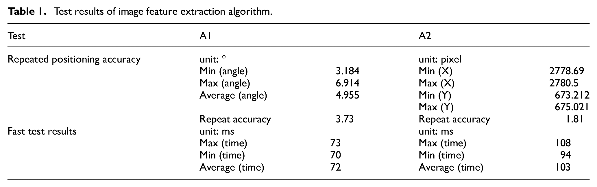
The two algorithms are executed 40 times, respectively, and the algorithm’s running time is counted to test the rapidity of the algorithm, as shown in Table 1. The computer’s CPU used to run these algorithms is Inter Core i7-9700k, with a frequency of 3.6 GHz. It can be seen from Table 1 that the time consumption of algorithm A1 and algorithm A2 is less than 200 ms, which has good rapidity and can meet the requirements of the system for real-time image processing.
Pressing and buckling
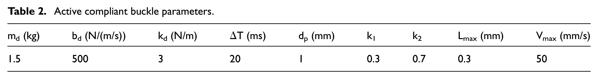
There are two cases for terminal head and terminal base when pressing and buckling: aligned and non-aligned because of the possibility of failed alignment. The successful alignment example is shown in Figure 16(a), and the failed alignment example is shown in Figure 16(b). The main influence parameters of the proposed force control algorithm are
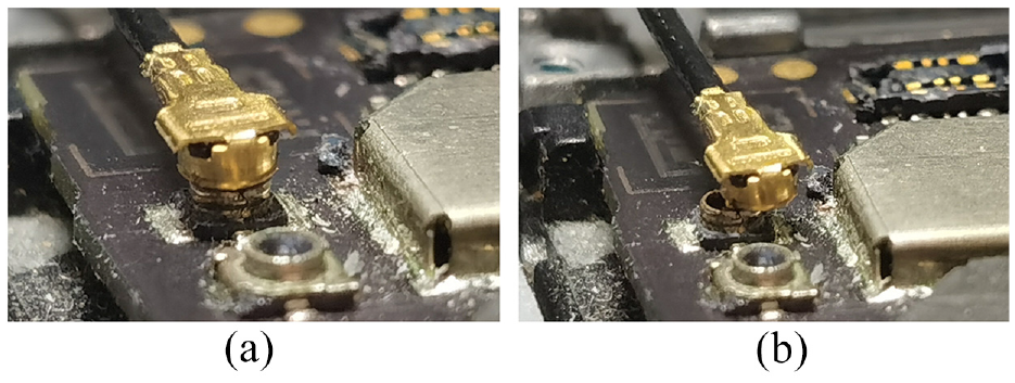
Two results of alignment: (a) the successful alignment of terminal heads and terminal bases and (b) the failed alignment of terminal heads and terminal bases.
Active compliant buckle parameters.
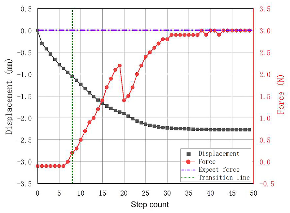
When the alignment is successful, the change of displacement and contact force of robot 2 in the Z direction is shown in Figure 17. The red curve represents the contact force. The purple dotted line represents the expected contact force. The vertical green dotted line represents the transition from free to contact space. The black curve represents the displacement change in the Z direction of the robot.
Change of displacement and contact force in case of successful alignment.
As described in the algorithm in Section 5, after the robot reaches the expected height, it starts to execute the switching strategy from free space to contact space mentioned in Section 5.2. Until the eighth motion cycle, the system detects that the contact force reaches the switching threshold. The force control algorithm of the terminal buckling process mentioned in Section 5.1 is turned on, and the contact force rises steadily. It can be seen that since the terminal head is buckled into the terminal base, the contact force between the terminal head and the indenter decreases, so from the 19th to the 20th movement cycle, the force suddenly decreases, and the movement in the Z direction is hardly affected. Then, after the contact force steadily increases to the target and is maintained for six motion cycles, the buckling is confirmed to end.
When alignment is failed, it means that the terminal head is located above the terminal base, but their centers are not aligned, and there is a deviation. In this case, the buckling cannot be realized, and the redundant displacement can be avoided through compliance control. In case of alignment failure, the change of displacement and contact force in the Z direction of the robot is shown in Figure 18.
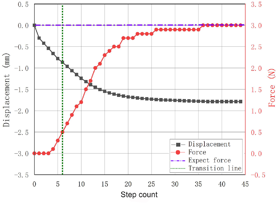
Change of displacement and contact force in case of alignment failure.
Compared with the successful alignment, it can be found that it only takes six cycles to reach the force switching threshold when the alignment fails. This is because the centers of the terminal head and the terminal base are misaligned, and the bottom of the terminal head will touch the top of the terminal base in advance. At the same time, due to buckling failure, there will be no sudden drop of contact force during the pressing process. The displacement in the Z direction of the contact space is at least 0.15 mm less than that of the successful alignment, which also proves that the method of judging whether the buckling is successful by using the displacement of the contact space in Section 5.2 is feasible.
Overall system performance test
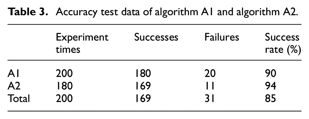
The success rate of the micro terminal buckling assembly system was tested based on vision and force feedback through 200 assembly experiments between terminal heads and terminal bases. For the rotation angle measurement of algorithm A1, after obtaining the rotation angle data, the system uses robot 1 to correct the angle. After correction, image acquisition and angle measurement shall be carried out once again. Considering the error of the rectified rotation angle and the repeated measurement accuracy of algorithm A1, only if the remeasured angle is within the range of [−3°, 3°], the subsequent assembly steps can be carried out. Otherwise, it is determined that the experiment fails. The number of experiment failures caused by algorithm A1 is 20. The main reason for the failure of the experiment was that the rotation angle of the terminal head was too large, which exceeded the limit of robot 1 by 20°. For a slight rotation angle (<20°), algorithm A1 can accurately measure it. For algorithm A2, this system judges whether the buckling between the terminal head and terminal base is successful. The test results are shown in Table 3. On the premise that algorithm A1 is successful, the success rate of algorithm A2 can reach 94%. The total success rate of terminal assembly using this system is 85%.
Accuracy test data of algorithm A1 and algorithm A2.
Conclusion
An automatic terminal buckling system with two cooperated manipulators is developed to realize the assembly of micro terminal heads with flexible lines buckled onto the terminal base in three-dimensional space. A visual algorithm based on the YOLOv3 network model and irregular image feature contour extraction is developed to accurately measure terminal heads’ position and spatial pose in a complex background. A total of 500 images were collected and made into a data set, of which 10% were used for testing and 90% for training. The target detection model trained by this data set has a detection accuracy of more than 99% under normal lighting conditions. Under other lighting conditions, the detection accuracy can also reach more than 95%. In the case of accelerated GPU, the detection time sampling a 3072 × 2048 image is about 65 ms. An impedance control algorithm is proposed to guide the contact process during pressing so as to protect components by controlling the force. This system combines visual and force information. It is a relatively comprehensive and advanced automatic assembly system at present. The method proposed in this paper provides a valuable idea for the field of automated assembly of micro terminals with flexible lines.
A series of manipulating experiments have been conducted in a real environment. In experiments, the pixel equivalence of the two industrial cameras is 0.0124 mm. The repeated measurement accuracy of the rotation angle is less than 3°. The repeated positioning accuracy of the visual algorithm is less than 2 pixels, and the success rate in 200 assembly experiments is 85%. The experimental results verified the effectiveness of the proposed assembly system and method. In the future, this method can be applied to the automatic assembly of more flexible components. This assembly system still has limitations. The accuracy and success rate of buckling need to be further improved. We will pay more attention to improving the efficiency of the automatic assembly system proposed in this paper and making it useful for other similar flexible components.
Highlights
The assembly system with two manipulators is developed to realize the assembly of micro terminals. A robot is used to grasp the terminal head, and the grasping position is on the line closing to the terminal head. The other robot is used for force-controlled press buckling.
Two cameras are used in the system. These two cameras do not form a binocular vision system but are separated. One camera is used to detect the rotation angle of the terminal head around the coaxial line, and the other is used to monitor the position deviation between the terminal head and the base.
A visual localization algorithm combining the YOLOv3 network model and irregular image feature contour extraction is developed to accurately measure the position and spatial pose of terminals in a complex background.
A force control strategy is proposed by combining the impedance algorithm with the force space switching algorithm. This strategy can solve the instability problem caused by the space switching of the end effector and the problem of component damage caused by excessive force during assembly.
Supplemental Material
sj-rar-1-mac-10.1177_00202940221144479 – Supplemental material for Automatic buckling system of micro terminals combined vision and force signals
Supplemental material, sj-rar-1-mac-10.1177_00202940221144479 for Automatic buckling system of micro terminals combined vision and force signals by Jinchao Jiang, Junxin Zhang, Jinhua Ye, Wenbo Zhou, Wei Chen and Haibin Wu in Measurement and Control
Footnotes
Declaration of conflicting interests
The author(s) declared no potential conflicts of interest with respect to the research, authorship, and/or publication of this article.
Funding
The author(s) disclosed receipt of the following financial support for the research, authorship, and/or publication of this article: This work was supported by the National Key Research and Development Project under Grant 2018YFB1308603 and by Intelligent Manufacturing Comprehensive Standardization Project under Grant GXSP20181001.
References
Supplementary Material
Please find the following supplemental material available below.
For Open Access articles published under a Creative Commons License, all supplemental material carries the same license as the article it is associated with.
For non-Open Access articles published, all supplemental material carries a non-exclusive license, and permission requests for re-use of supplemental material or any part of supplemental material shall be sent directly to the copyright owner as specified in the copyright notice associated with the article.