
Abstract
To achieve stabilisation control of an underactuated bridge crane system, a new robust control strategy for the sliding mode is proposed in this paper. It can realise finite-time-convergent stabilisation control under the conditions of model uncertainty, parameter perturbation and external interference. In contrast to the existing methods, our method does not need prior information of the dynamic characteristics of the bridge crane system, and can make the system converge to the equilibrium state at the preset time. Specifically, the nonlinear model of the bridge crane system is linearised with partial feedback, and adaptive signals are introduced. Then, according to the form of the transformed system, a fast terminal sliding mode surface is constructed, and an adaptive terminal sliding mode controller is designed. According to strict analysis, the proposed control law ensures that the system converges to the equilibrium point in finite time and provides the convergence time. Finally, the effectiveness and robustness of the proposed control method are verified by comparing the simulation and experimental results with existing methods.
Keywords
Introduction
As one of the most common handling tools of heavy cargo, bridge cranes have been widely used in various applications of national economic construction, such as in ports, steel mills, nuclear power plants, workshops and road construction. The main control objective of a bridge crane system is to achieve fast and accurate ‘point-to-point’ transportation of payloads. Nevertheless, owing to the underactuated characteristics of the system and a variety of external interferences, the payload is prone to swing significantly during handling, which seriously affects the positioning accuracy of the payload. This not only reduces the working efficiency of the system, but also introduces many unsafe factors. The primary problem of automatic control of a bridge crane system is to ensure fast and accurate positioning of the trolley and fully restrain the swing angle of the payload.
From the perspective of control, the trolley displacement and swing angle of the payload are selected as the control variables, and the driving force is selected as the control quantity for a 2-DOF bridge crane system. As a consequence, the only way of elimination of the payload swing is to suitably control the trolley movement by designing the controller. The existing control modes of the control systems of bridge crane can be divided into two types: open-loop control and closed-loop control. The representative methods of open loop control include input shaping1,2 and offline trajectory planning,3–5 which can precisely plan the movement of the trolley to accurately locate and suppress the swing of the payload. Although this type of method can achieve better control results in an indoor environment without interference, the control accuracy depends on the natural frequency of the system. In addition, it relies on pre-planning, which makes it impossible to compensate for external random interference in real time. In contrast, the robustness of the system is improved because the immediate feedback signal is fully utilised by closed-loop control. A better control effect is obtained, even in the case of external interference. Therefore, a series of closed-loop control methods have been proposed, including model predictive control, 6 adaptive control,7,8 output-feedback control,9,10 intelligent control,11–14 energy-based control15–18 and sliding mode control.19–29
The design of bridge crane control systems often involves the problems of model uncertainty, parameter perturbation and external interference in practical industrial applications, which can be solved by the sliding mode control efficiently. For example, a decoupling sliding mode control method was proposed in Yu et al., 22 which has been widely applied in various engineering domains owing to its simple structure and sensitive response. In Xu and Xu, 23 the authors designed a time-varying sliding mode surface to replace the traditional linear sliding mode surface and effectively improved the robustness of the system. And a global sliding mode surface is established to ensure that the system state is located on the sliding mode surface from the beginning, which solved the problem of robustness in the approaching stage of the sliding mode. 24 However, the aforementioned sliding mode control methods can only ensure the gradual stability of the system instead of the guarantee of the finite-time convergence. Hence, in Chwa, 25 a fast terminal sliding mode control method was proposed, which not only guaranteed the finite-time convergence of the system, but also calculated its convergence time. Although the above methods are classic closed-loop control methods, it is difficult to determine an accurate nonlinear physical model. Such types of control methods based on dynamic models are difficult to satisfy engineering practices, and the values of the physical parameters in the model also deviate from the actual values, that is, the parameters perturbation. In this regard, Bu et al. 26 transformed the pure feedback system into a strict feedback system, and studied a new model-free controller composed of Hurwitz stability term and filter term. The controller does not need accurate affine model and has good versatility and strong robustness. However, the control method based on hypersonic vehicle cannot be directly applied to bridge crane system, and there is room for improvement in dynamic control performance. Therefore, Sun et al. 18 constructed an output feedback passive function and designed an output feedback controller without model parameters based on the principle of energy exchange and dropping. As the system model parameter-related terms were not introduced into the control law, the control performance was less dependent on the accuracy of the parameters. Zhang et al. 27 designed an adaptive controller to predict the system model information existing in the designed PD-SMC controller, in order to reduce the sensitivity of the controller to perturbation of model parameters. However, it only performed adaptive estimation on some of the model parameters, and adaptive robust control effect could not be completely realised.
Based on the above analysis, in this paper, we propose a model-free finite-time adaptive terminal sliding mode controller suitable for bridge crane systems. This controller can accelerate the system convergence, make the system reach a stable equilibrium state at the set time, and ensure the stability of the system with model uncertainty, parameter perturbation and external interference. First, the model is appropriately transformed, and the adaptiveness of the physical parameters is introduced. On this basis, a fast terminal sliding surface is designed, and a finite-time controller is proposed. By introducing the Lyapunov function, the stability of the closed-loop system is proven, and the finite time T is calculated. The effectiveness and robustness of the proposed control method are verified by comparing the simulation and experimental results with existing control methods.
In summary, the main contributions of this article are as follows:
(1) The designed method does not need information of the dynamic characteristics of the bridge crane system and has good robust control performance; that is, the designed controller is a model-free robust controller.
(2) The design obtains the finite convergence time T of the control system through rigorous theoretical analysis and calculation, based on the fast terminal sliding mode control method.
(3) Owing to the special structure of the switching function, the control quantity itself and its rate of change are guaranteed to be continuous, and chattering and potential damage to the execution device are avoided.
The remaining sections of this article are arranged as follows. In Section 2, the dynamic model of the overhead crane system is presented, its control problems and control objectives are described, and adaptive signals are introduced for model transformation. In Section 3, a detailed controller design process is presented, and its performance is analysed through two theorems. In Section 4 and Section 5, simulation results and experimental results are presented to verify the control performance and robustness of the proposed method, and in Section 6, we summarise the structure of this study.
Problem statement
The dynamic equation of the bridge crane (shown in Figure 1) is described as follows:


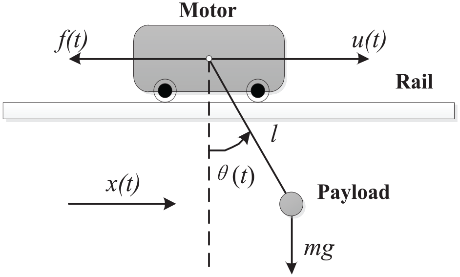
Physical model of the bridge crane.
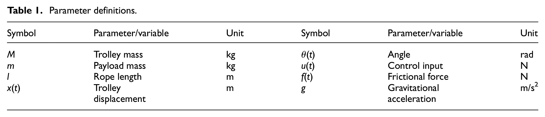
The definitions of the variables and parameters in equations (1) and (2) are listed in Table 1. To analyse the friction between the trolley and track, the following model is used 27 :
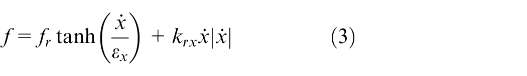
Where fr, εx, krx∈R are the corresponding friction coefficients.
Parameter definitions.
Considering the real working conditions of the crane system, without loss of generality, the following assumptions are made.
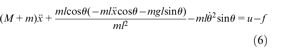
Partial feedback linearisation is performed on the crane dynamics equation, aiming to transform the crane dynamics model into a form that is convenient for controller design through coordinate transformation (see equation (7)). Hence, equation (2) is arranged into the following form:
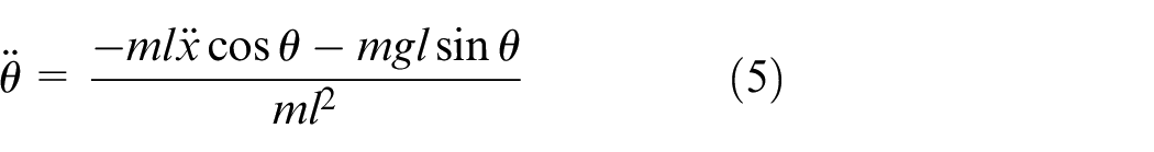
Substituting equation (5) into equation (1), we obtain
Equation (5) can be further simplified. Setting

where P(θ) is a state-variable function, and is defined as

Taking the derivative of P(θ), and considering the estimator error

For the bridge crane system, the control objective is to make the trolley reach the target position xf quickly and accurately, while fully restraining and eliminating the swing of the payload during the entire process, namely,

Major results
In this section, an adaptive terminal sliding mode controller is designed for a bridge crane system. Through theoretical analysis, its boundedness and finite-time convergence are proved, and its arrival time T is calculated.
Controller design
To improve the control performance of the bridge crane system, the coupling between the trolley displacement x(t) and the payload swing angle θ(t) is enhanced, and the following composite signals are introduced:
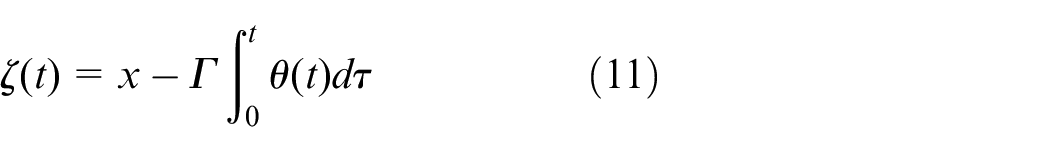
Here, Γ is a positive control gain. Therefore, its first and second derivative functions are expressed as


To achieve the control objective shown in equation (10), the following deviation signal e(t) is introduced:

Based on (14), the sliding mode dynamic s(t) is constructed as
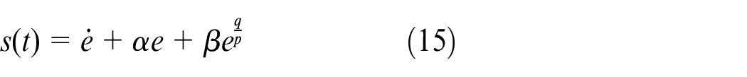
In the equation, α, β, σ, q, p
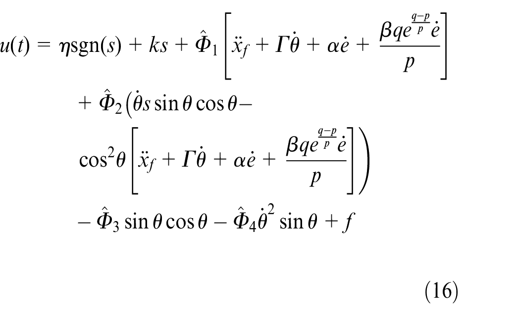
where η, k
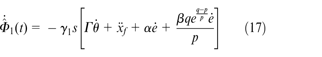
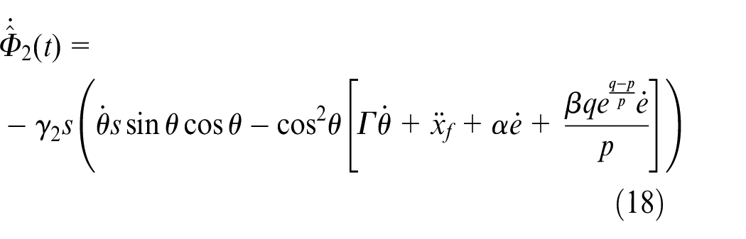
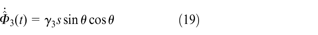
In the equations, γ1, γ2, γ3, γ4 are all positive constant.
Next, two theorems are used to prove that in the presence of an external disturbance d(t), the controller (16) can ensure that the system state reaches the sliding mode surface s(t) = 0 at the time of arrival
Stability analysis
According to equations (4) and (8), for
Taking the derivative of V1(t), the following results are obtained:
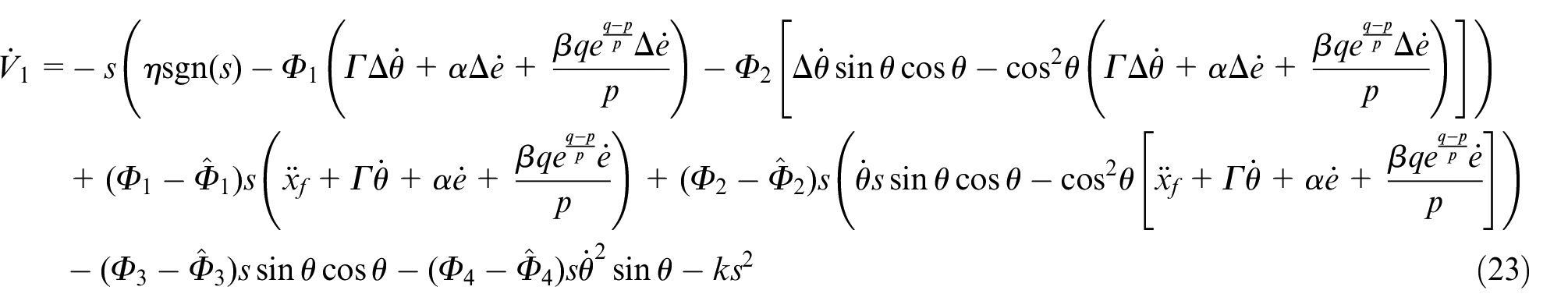
where
A positive definite scalar function V(t) is constructed as follows:
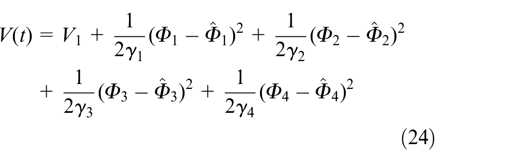
Differentiating and substituting equation (22) and adaptive laws (16)–(19) into (24), we obtain
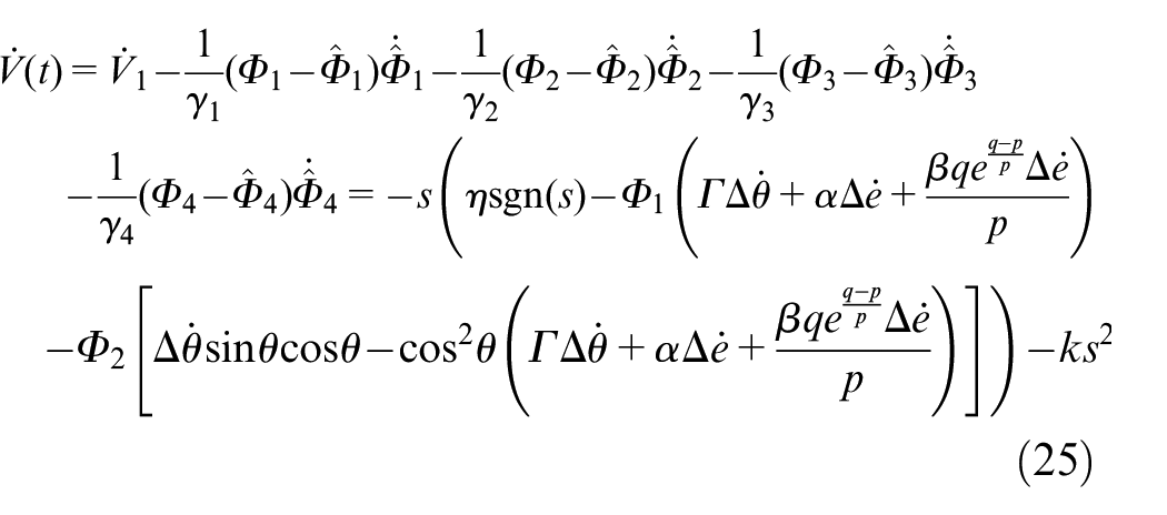
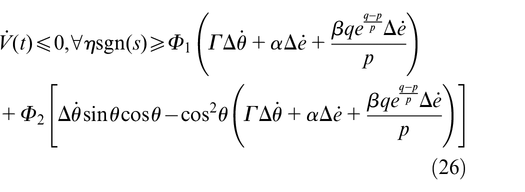
Evidently, for bounded estimation errors,
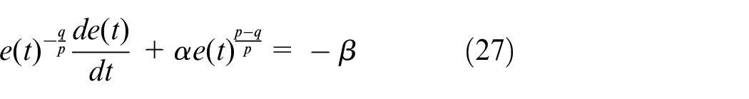
Defining the following auxiliary signal y(t) = e(t)1−q/p, we can derive
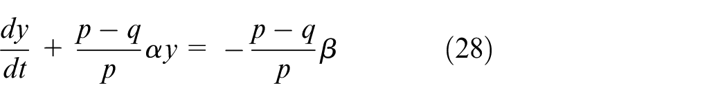
The general solution of the first-order linear differential equation shown in (28) is
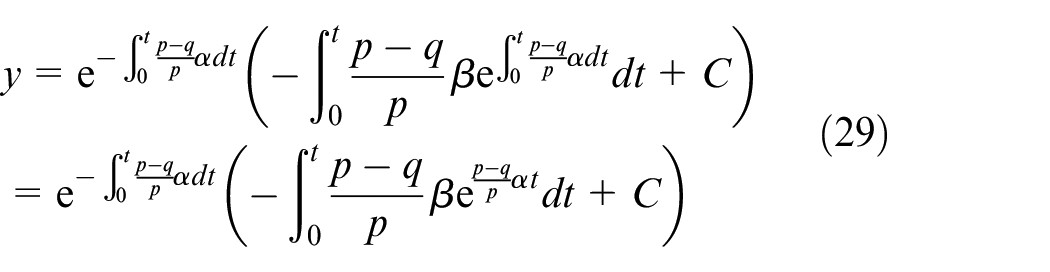
when t = 0, C = y(0) = e(0)1−q/p, and we obtain
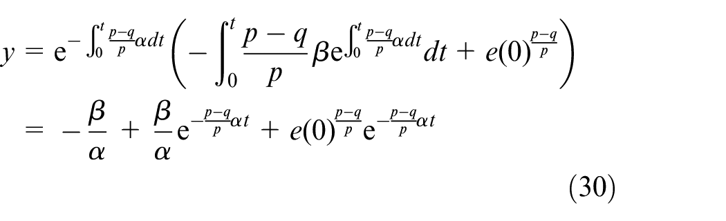
It is obvious that y = 0, t = T when e = 0 at which the control objective shown in equation (10) is achieved, and equation (30) can be simplified as
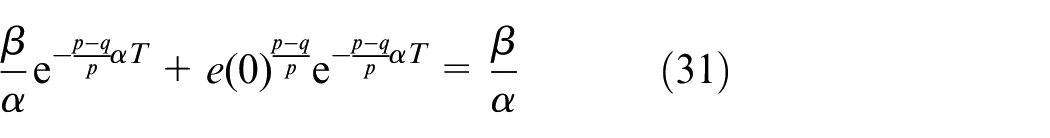
Then
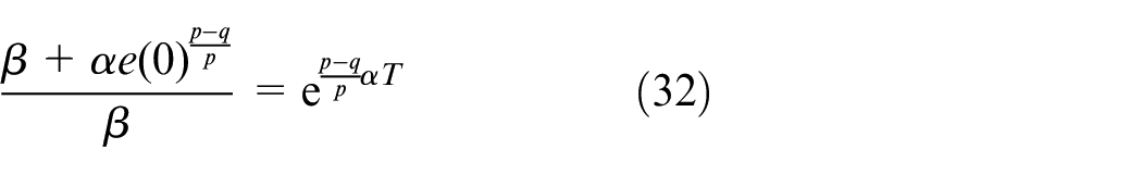
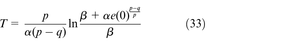
The time for the system state variables to converge from any initial state x(0) ≠ 0 to the equilibrium state x = 0 in the sliding mode is
Thus, theorem 2 is proved.
Simulation and analysis
In this section, the control method proposed in this paper is tested for a bridge crane using the MATLAB/Simulink simulation. It is compared with the LQR controller 27 and the multi-sliding mode controller (MSMC) 29 to verify the effectiveness. The results show that the proposed method not only achieves better transient performance, but also effectively reduces system energy consumption.
The physical parameters of the bridge crane simulation experiment platform are set as follows. The mass of the trolley and the payload, and the length of the sling are selected as

We set the target position of the crane as

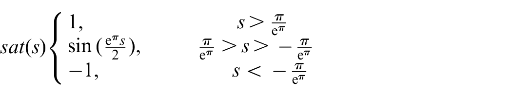
To weaken the chattering phenomenon of the designed controller, a continuous switching function sat(*) is designed to replace the symbolic function sgn(*) in the controller (15), and the specific definition is as follows:
Two representative controls of multi-sliding mode control (MSMC) and LQR control are introduced for comparison with the method proposed in this paper. To ensure the completeness of the narrative of the paper and facilitate the description of the experimental results, the specific structures of these methods are described in equations (33) and (34). The expressions of the controllers have been adjusted, because the reference direction of the swing angle in this study is different from the other two algorithms. The results are presented below.
(1) LQR controller u1(t):

Here,
(2) Multi-sliding mode controller u2(t):
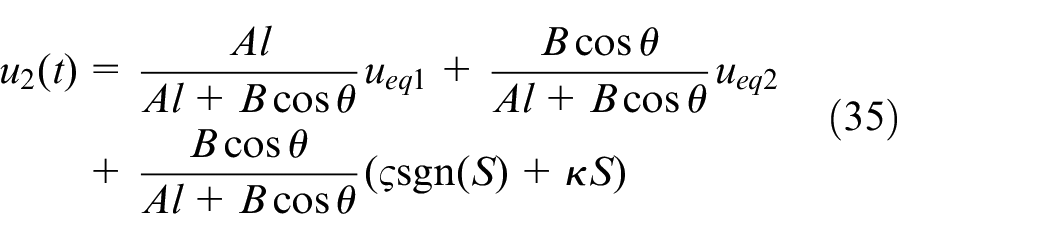
Here,
Here,
In subsequent simulations and experiments in each group, the friction force shown in equation (3) is used to carry out feedforward compensation for the control system. After fully debugging the controller (16) and the above two control methods (34) and (35) designed in this study, we obtain the experimental results shown in Figures 2 to 5. The control gains of each controller are listed in Table 2.
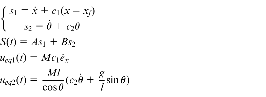
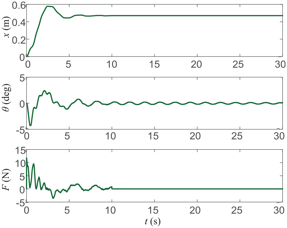
Results of simulation group 1 (proposed controller): (a) performance of crane control, (b) performance of parameters estimation.
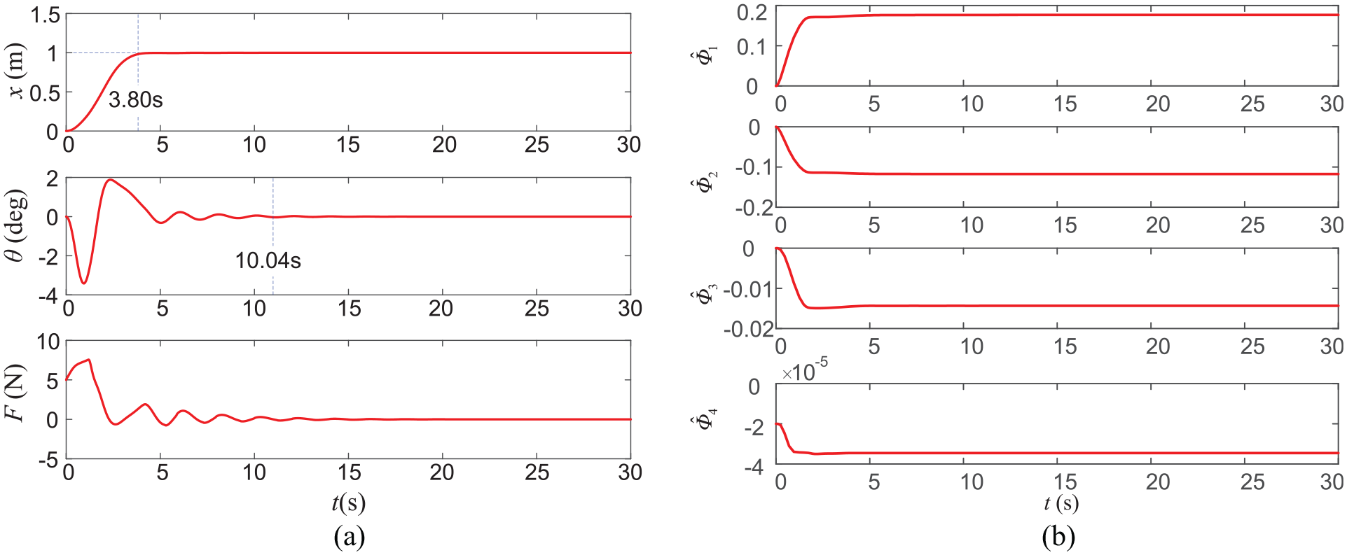
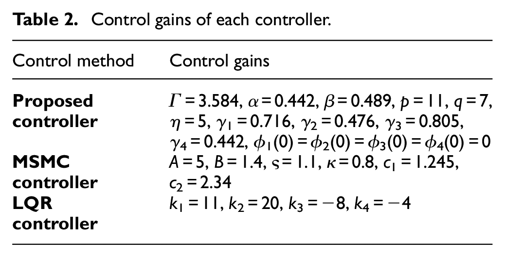
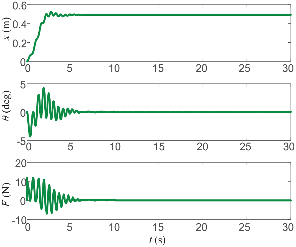
Results of simulation group 1 (MSMC controller).
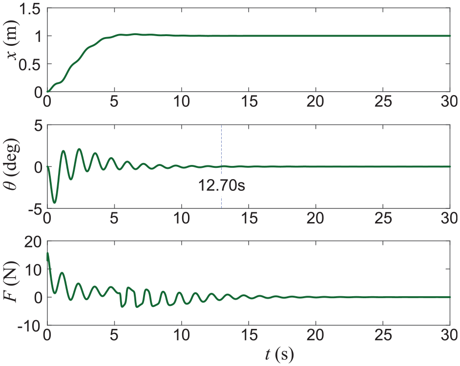
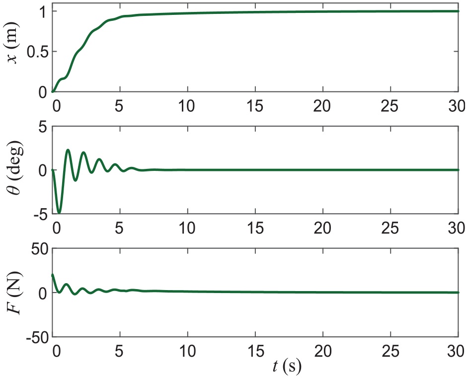
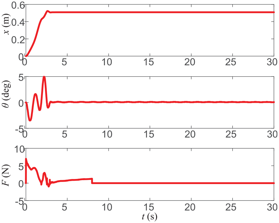
Results of simulation group 1 (LQR controller).

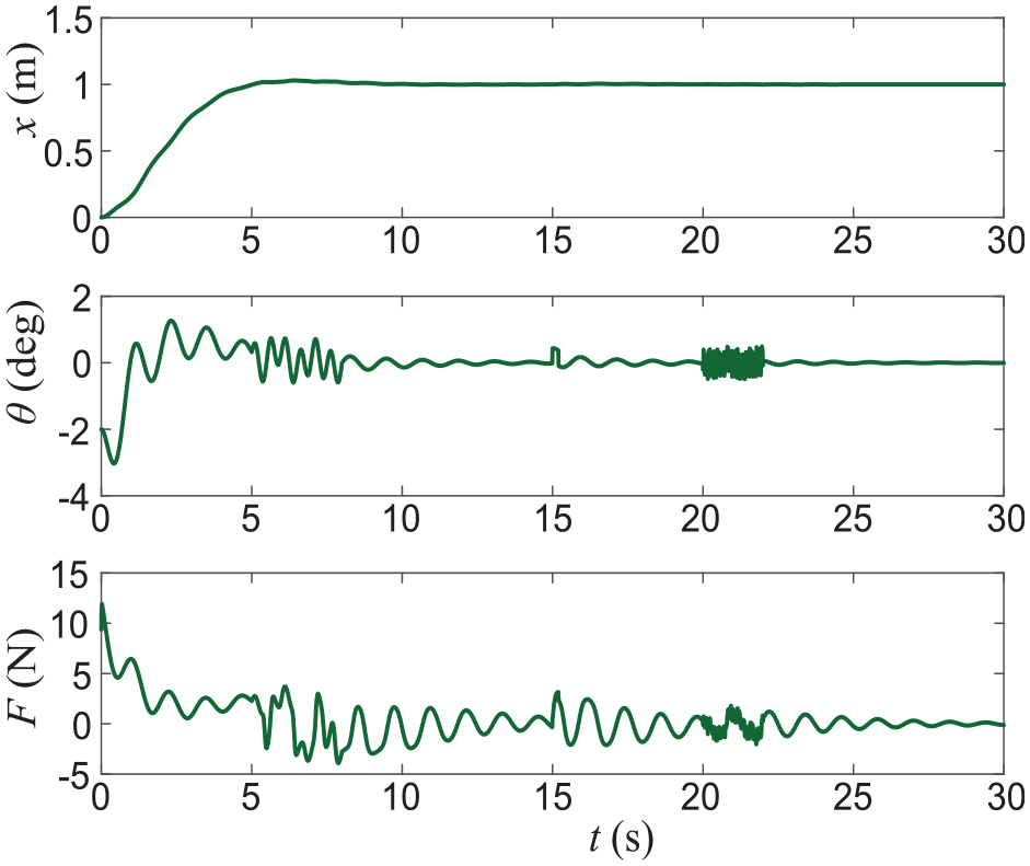
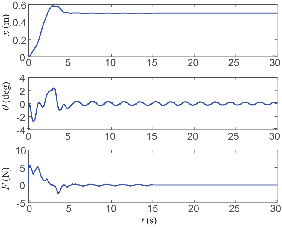
Results of simulation group 2 (proposed controller).
Control gains of each controller.
In addition, to verify the control performance of the proposed method more comprehensively, three sets of simulation tests under different conditions were conducted. The experimental results of simulation groups 1, 2 and 3 are shown in Figures 2 to 10, respectively. The trolley displacement, payload swing angle and control input are shown in each figure.
Results of simulation group 2 (MSMC controller).
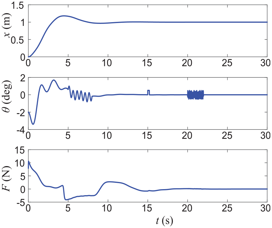
Results of simulation group 2 (LQR controller).
Results of simulation group 2 (proposed controller).
Results of simulation group 2 (MSMC controller).
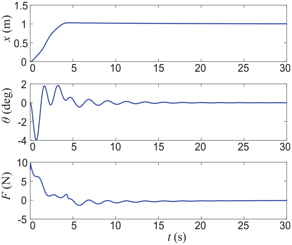
Results of simulation group 3 (LQR controller).
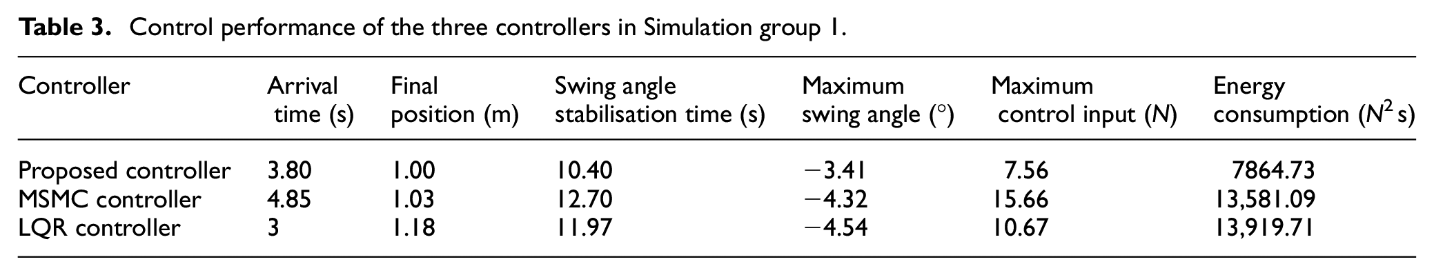
Furthermore, Tables 3 and 4 show the quantified data of the experimental results, where the residual swing angle represents the maximum swing of the payload when the crane stops running. Stabilisation time refers to the time required for the swing angle to stabilise within ±0.02°.
Control performance of the three controllers in Simulation group 1.
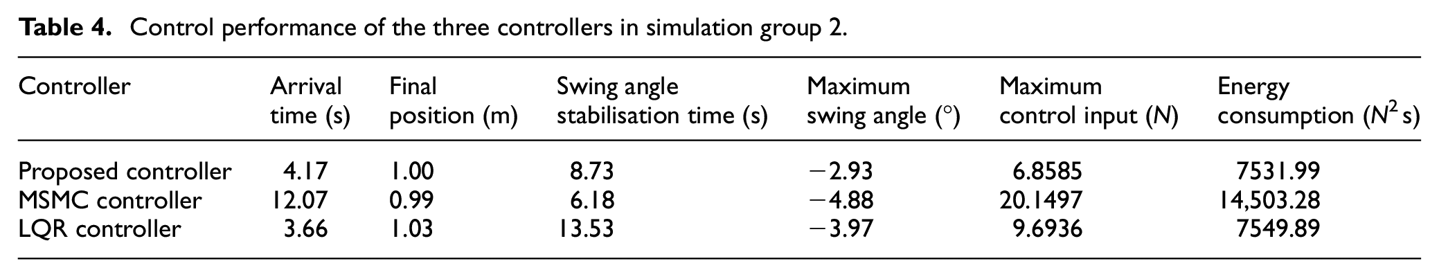
Control performance of the three controllers in simulation group 2.
To characterise the energy consumption of the system, the cumulative energy consumption E is defined to measure the required drive energy consumption of the controller:
The specific arrangement of the simulation experiment is as follows:
Simulation group 1: The superiority of control performance without interference and finite-time convergence of the proposed method are verified.
The simulation results are shown in Figures 2 to 4, which are the control results of the proposed controller, MSMC controller and LQR controller, respectively. In Figures 2(a), 3 and 4, the trolley displacement, payload swing angle and trolley driving force are shown. Table 3 shows the results of quantifying the experimental data.
By comparing Figures 2 to 4 and analysing the performance data of each controller in Table 3, it is observed that under the action of different controllers, the trolley can accurately reach the expected position within 5 s. By further comparing the experimental data, the results are as follows: (a) in terms of trolley movement, the proposed controller has a faster reach and higher convergence accuracy than the MSMC method. Although it is slower than the LQR controller (arrival time is 3 s), the latter has an obvious overshoot, and the stabilisation time is approximately 11 s. (b) In terms of swing suppression of the payload, the proposed controller has a faster swing angle stabilisation speed and a smaller swing amplitude than the other two controllers in the entire control process. (c) The proposed controller has significantly lesser energy consumption and maximum driving force of the trolley than the other two controllers. This also implies that it has low requirements for the performance of the system actuators, and has good prospects for practical applications.
The parameters estimation of the adaptive method proposed in this paper is shown in Figure 2(b), which clearly indicates that all the estimates converge at about 5 s. In addition, according to equation (32) and the controller parameter settings of the simulation experiment described in this section, the calculated arrival time T is
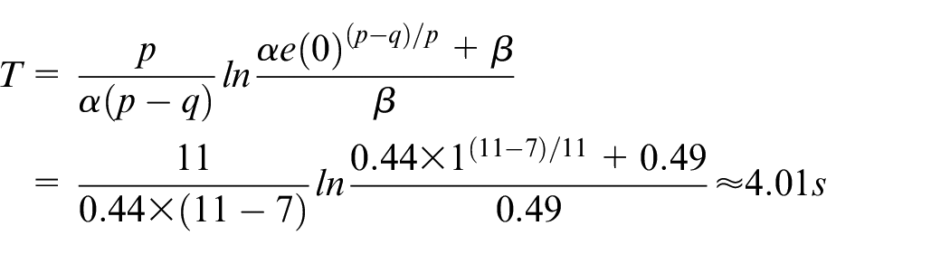
The arrival time T calculated by the method in this paper is 4.01 s and the simulation result in Figure 2 is 3.80 s. Additionally, the error is only 5%, which verifies that our method converges in a finite time. The control performances obtained from the control simulation results of the three controllers are listed in Table 3.
Simulation Group 2: Robustness verification for a perturbation of physical parameters and unmodelled dynamics.
The model parameters of the actual dynamics system were:

The relevant physical model parameters in the controller are set as:

From Figures 5 to 7 and Table 4, we observe that the proposed control method achieves superior overall performance under the parameter perturbation conditions set in simulation group 2, and the arrival speed and accuracy of the trolley are closer to those of simulation group 1. In terms of payload swing suppression and energy consumption, the performance is better than in the case when the parameters are accurate. However, the bridge crane system under the action of the MSMC controller and the LQR controller is significantly affected by parameter perturbation, and the control effect is significantly deteriorated. Compared with simulation group 1 (corresponding to Figures 3 and 4), this result is worse in terms of the trolley transportation time and payload stabilisation speed. This also shows that the proposed controller is more robust than the other two in resisting the influence of parameter perturbation without adjusting the controller parameters.
Simulation Group 3: Robustness experiment: During operation, the bridge crane system suffers from external interference mainly from the impact of collision, wind, etc. on the payload movement.
To verify the robustness of our method to lumped interference, the following interference was artificially added to the swing angle of the payload during the simulation process:
(1) θ(0) = −2°.
(2) A sine wave perturbation is induced, with a relative amplitude of 15% and a frequency of 4π between 5 and 8 s.
(3) We added pulse interference with a relative amplitude of 15% and a pulse width of 0.2 s between 15 and 15.2 s.
(4) Random interference was added with a relative amplitude of 15% between 20 and 22 s.
The relative amplitude is defined as the percentage value of the swing angle interference amplitude and the maximum swing angle amplitude of the payload in the entire process. The corresponding simulation results are shown in Figures 8 to 10.
Figures 8 to 10 show the control performance curves of the three bridge crane control systems under the influence of various interference signals. Comparing and observing the control performance of the three controllers, it can be concluded that under the conditions of simulation group 3, the three controllers can return to a stable state after the end of interference. Further analysis shows that after sine wave interference (5–8 s), the method proposed in this study as well as the LQR controller can be stabilised within 1.5 s, while MSMC requires 3 s to achieve the same effect. After rectangular wave interference (15–15.2 s), all three controllers can stabilise the swing angle to 0° within 1 s. Among them, the residual payload swing is the smallest under the action of the LQR controller, but it requires a larger driving force to resist the influence of interference signals. In addition, in the non-zero initial state, our method requires less initial control than the other two methods, the motion curve of the trolley is smoother, and the positioning performance is almost unaffected (compared with Figure 2). This indicates that the proposed controller exhibits good robustness under various disturbances.
Physical experiment
To further verify the practical application performance of the proposed model-free adaptive fast terminal sliding mode control method, some hardware experimental results are presented in this subsection. Moreover, a self-built overhead crane testbed is shown in Figure 11 was used for experimental verification. As can be seen from the figure, the trolley moves along and horizontally under the drive of the servo motor, and the displacement of the trolley is measured by the encoder installed in the servo motor. Meanwhile, the encoder fixed under the trolley can capture the swing Angle of load in real time through special mechanical structure. The experimental testbed was based on the real-time control environment of the Real Time Windows Target (RTWT) under the Windows 7 operating system. We used MATLAB/Simulink to calculate and generate control commands online, and set the control cycle to 5 ms.
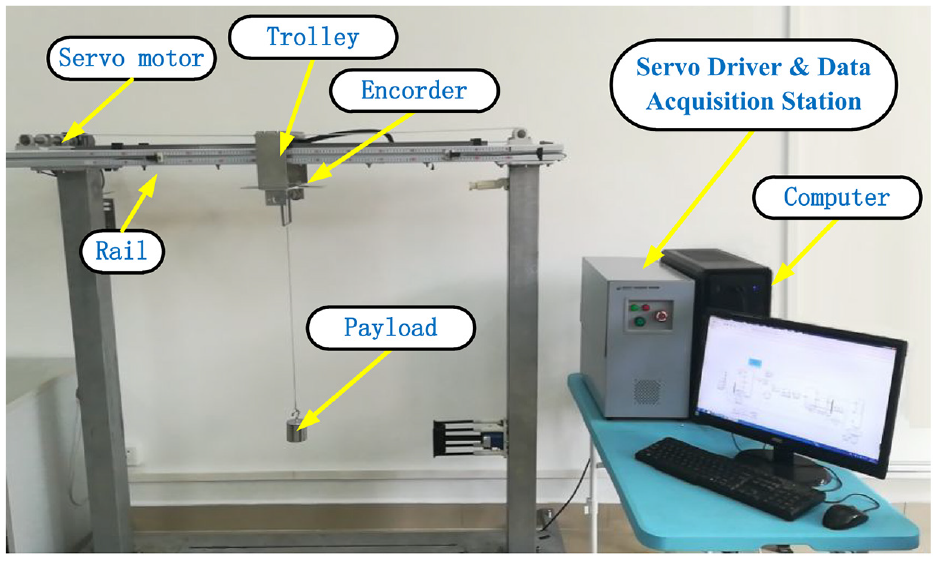
Bridge crane test platform.
The physical parameters of the experiment setup are M = 3.139 kg, m = 2 kg, g = 9.8 m/s2, l = 0.75 m (except for Case 1 in Experiment 2). After numerous tests, the friction damping coefficient between the trolley and the track is set as fr = 1.023 × 10⁴, εx = 395.3, krx = 46.96.
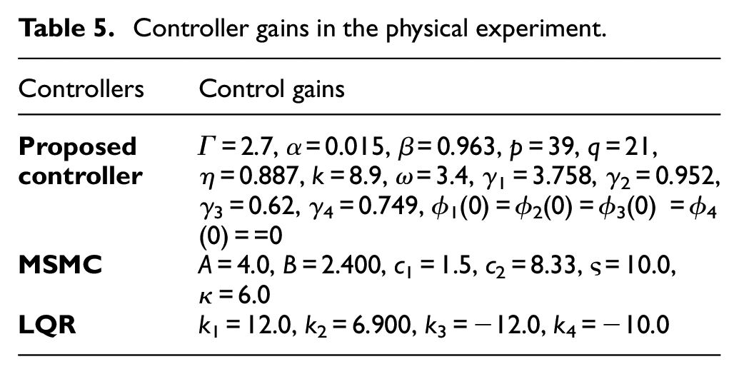
The target position of the trolley is set as 0.5 m. The control gain settings of the relevant controllers in both sets of experiments (after full debugging) are listed in Table 5. To comprehensively validate the performance of the proposed control strategy, two groups of experimental tests are carried out. To be specific, The control performance of the three control methods will be compared and analysed in the first group of experiments Subsequently, to verify the robustness of the proposed method, the off-stage working environment under different working conditions is simulated, and the control performance of the three methods is compared.
Controller gains in the physical experiment.
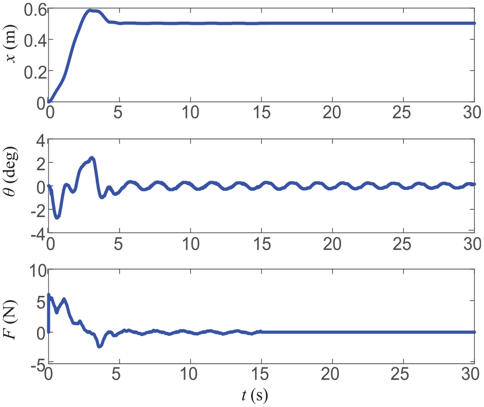
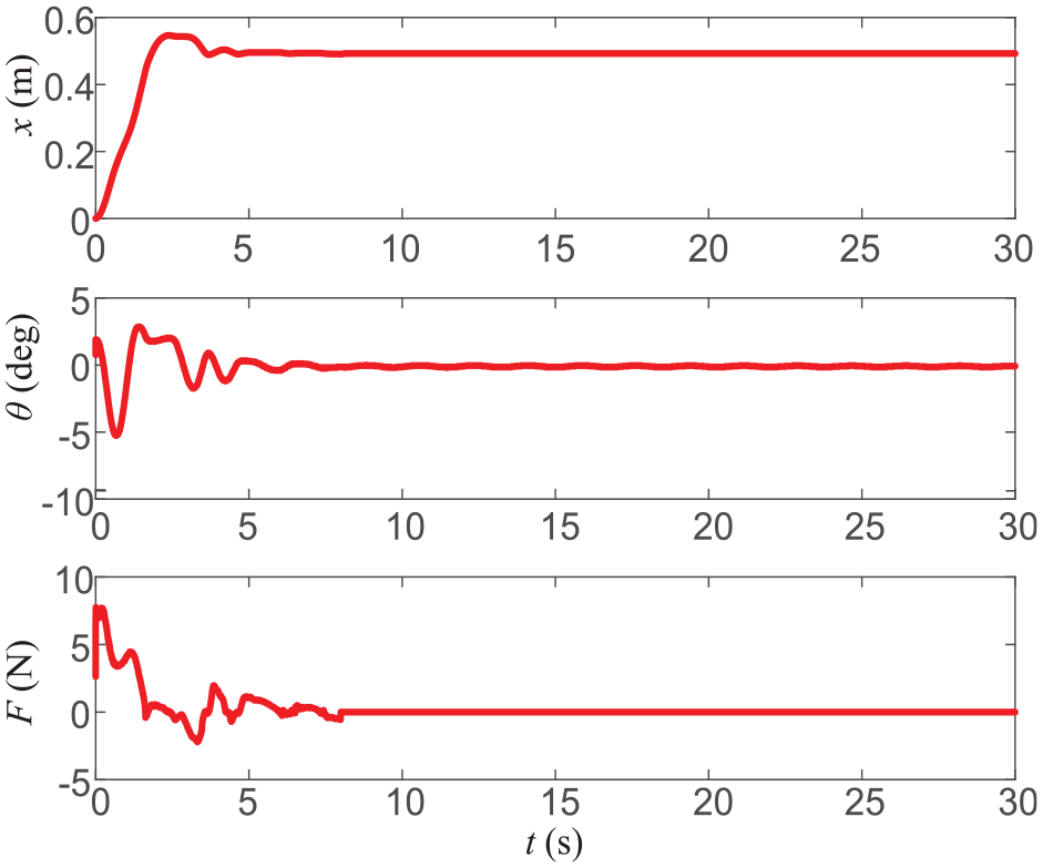
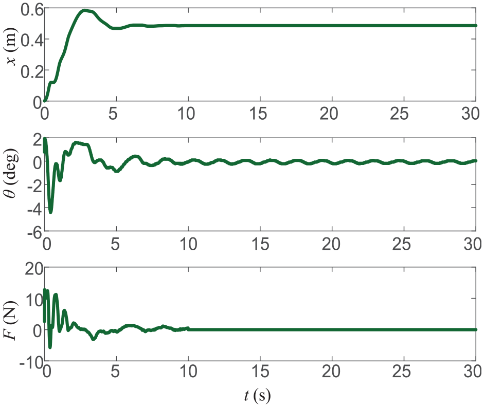
Experimental Group 1: Comparative experiment: Comparing the control performance of the proposed control method with that of the MSMC and LQR methods at zero initial swing angle and with accurate system model parameters, the experimental results are shown in Figures 12 to 14.
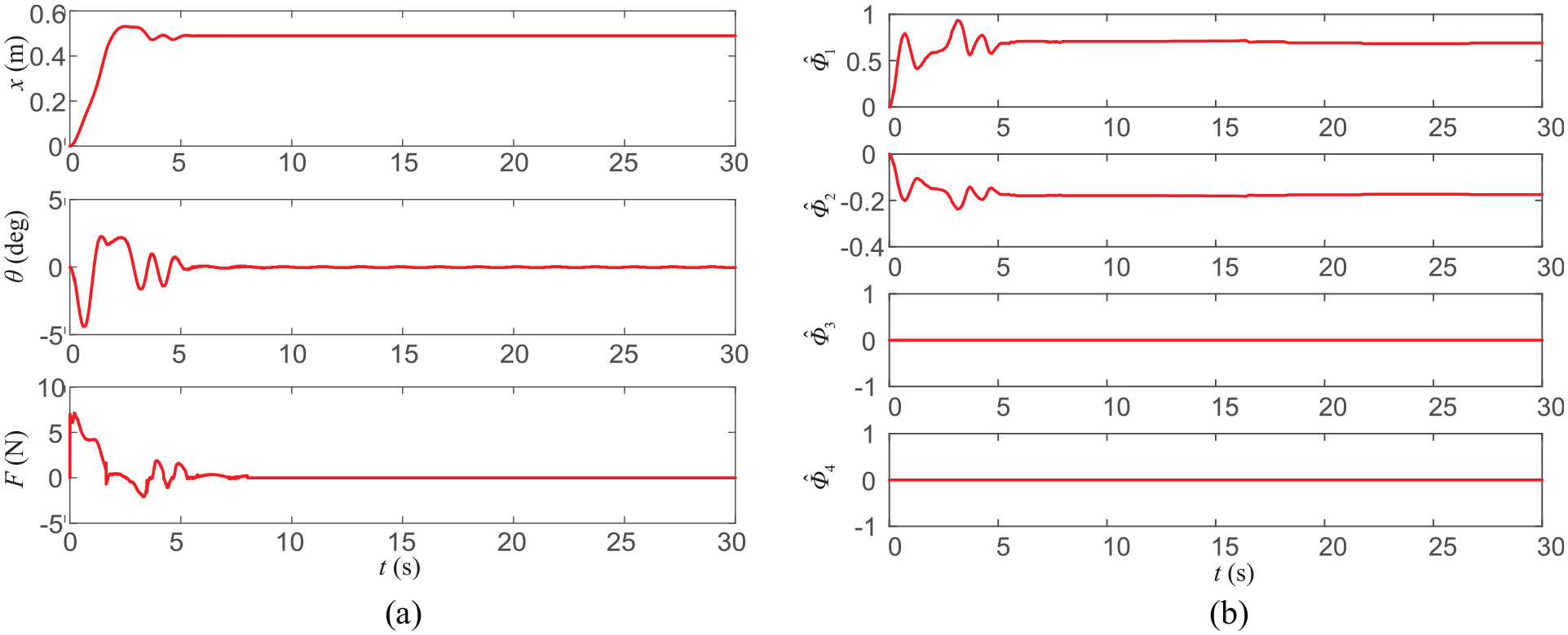
Results of experimental group 1 (proposed controller): (a) performance of crane control, (b) performance of parameters estimation.
Results of experimental group 1 (MSMC controller).
Results of experimental group 1 (LQR controller).
By observing the change in system state volume under the three control methods, the trolley converges to the target position within 8 s and suppresses the residual swing of the payload within 15 s. The proposed method has the advantages of faster convergence (6 s), smaller overshoot (0.02 m) and smaller residual swing angle than MSMC and LQR control. Although it causes a large swing (approximately −4.7°) in the beginning, which is slightly larger than LQR and significantly better than MSMC, thereafter, it is significantly faster than the other two control methods in terms of angle convergence. The results above demonstrate the adaptability and robustness of the proposed method, which is safer and faster for practical engineering applications.
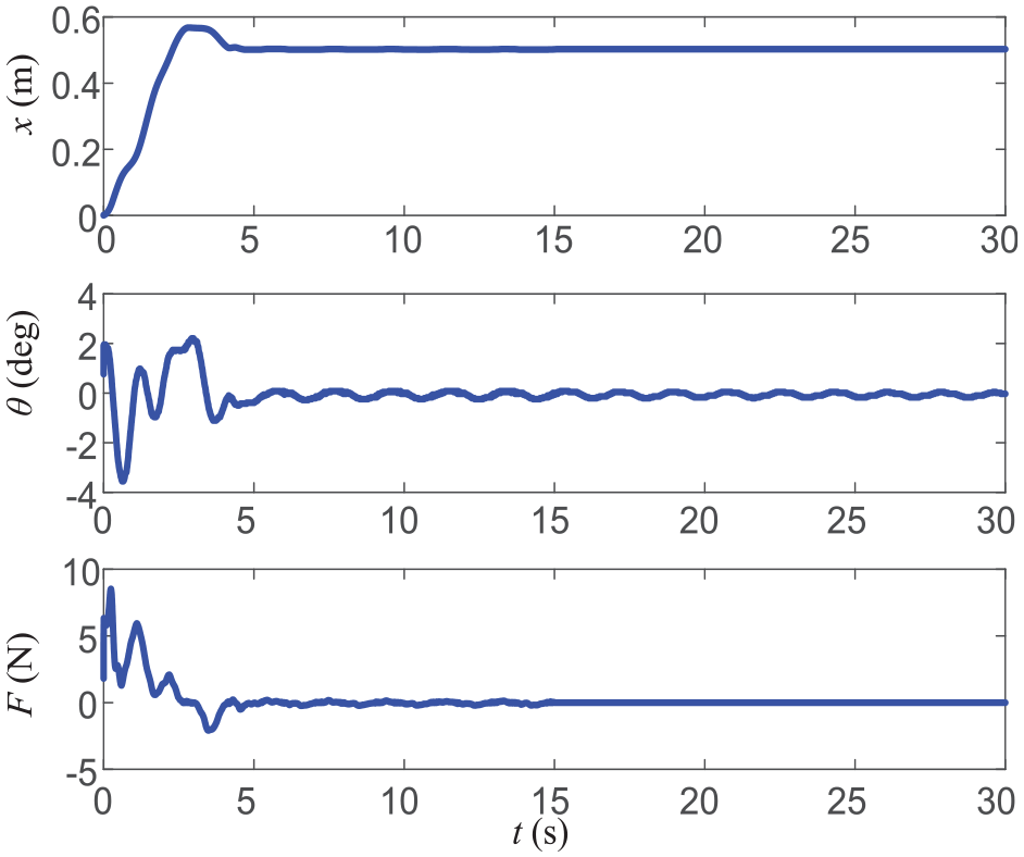
Experimental Group 2: Robustness verification experiments: In this experiment, to verify the robustness of the proposed control method to changes in system parameters and external disturbances, the following two cases are considered.

The experimental results of the proposed controller and the other two controllers are shown in Figures 15 to 17.
Results of case 1 (proposed controller).
Results of case 1 (MSMC controller).
Results of case 1 (LQR controller).
Results of case 2 (proposed controller).
Results of case 2 (MSMC controller).
Results of case 2 (LQR controller).
Under the condition of inaccurate system model information, the system state under ATSMC control is sufficiently close to the desired equilibrium point within 3 s without an obvious overshoot. At the same time, the residual swing of the payload is eliminated, and anti-swing positioning control of the underactuated crane system is realised. In contrast, for MSMC and LQR, each trolley converges to the desired position in approximately 5 s. Among them, MSMC eliminates the residual swing angle at 6 s. Although the LQR method can effectively suppress the amplitude swing amplitude, its residual swing angle elimination performance is poor, and the payload swing angle converges to within ±0.02° at approximately 8.55 s. In terms of output force, the maximum driving forces of the two sliding mode control methods (ATSMC: 7.01 N, MSMC: 11.75 N) are greater than that of LQR control (5.98 N). However, there is a smaller gap between the energy consumption of the proposed method and that of the LQR method. In summary, compared with the other two control methods, ATSMC has strong robustness to the crane system under the influence of parameter perturbation.
Comparing the results of experimental group 1 (Figures 12–14), in the non-zero initial state, the three control methods have varying degrees of overshoot, and the maximum control amount also increases. However, all three control methods cause the system to converge to a stable state within 8 s. Further analysis shows that the trolley convergence speed (ATSMC: 4.8 s, MSMC: 7.3 s, LQR: 5 s) and overshoot (ATSMC: 0.04 m, MSMC: 0.09 m, LQR: 0.08 m) are smaller. In addition, although the payload swing of the proposed controller is slightly larger than that of the other two control methods, it has significant advantages in terms of payload swing stabilisation. This shows that the proposed controller has high reliability and safety even when the initial state changes, and is more suitable for payload transportation tasks under complex working conditions.
Conclusions
In this study, a model-free adaptive terminal sliding mode controller suitable for bridge crane systems has been designed. By constructing a new adaptive terminal sliding mode controller for an overhead crane system, this method significantly reduces the influence of parameter perturbation and model uncertainty on the crane control during operation. Specifically, partial feedback linearisation is performed on the model, and a new deviation signal is defined. On this basis, a fast terminal sliding mode controller is designed. Then, according to the rules of the controller and the model, an adaptive controller is constructed to estimate the physical parameters in the controller, and an adaptive terminal sliding mode controller is designed. Strict mathematical analysis proves that the closed-loop system is asymptotically stable in the sense of Lyapunov and calculates its arrival time. Finally, simulation and experimental results show that the control strategy proposed in this paper can achieve better control performance than conventional model-free methods and sliding mode control methods. The follow-up research will focus on reducing the energy consumption of the control system and the initial control amount and on improving the robustness of the system further.
Footnotes
Declaration of conflicting interests
The author(s) declared no potential conflicts of interest with respect to the research, authorship, and/or publication of this article.
Funding
The author(s) disclosed receipt of the following financial support for the research, authorship, and/or publication of this article: This work was supported by the National Natural Science Foundation of China (Grant No.51505154, 51437005) in part, the Science and Technology Project of Jiangmen City (Grant No.2020JC01035, 2019JC01005, 202103013260007341) in part, the Special projects in key areas of Guangdong Province (Grant No. 2021ZDZX1086) in part, and the Teaching quality engineering and teaching reform project in Guangdong Province (Grant No. GDJX2019012).