
Abstract
To improve the accuracy of speed estimation strategy over a wide speed range in the sensorless speed control system of an interior permanent – magnet synchronous motor (IPMSM), a full-order adaptive observer based on a novel fast super-twisting algorithm (NFSTA-AO) is proposed. The conventional model reference adaptive system (MRAS) takes the linear compensation matrix of the unit matrix, which can only achieve speed discrimination within a certain speed range. Therefore, in this paper, a new linear compensation matrix is first derived using Popov’s super stability theory, and then, a new tachograph – adaptive law is obtained. A feedback correction link is also added to the adjustable model to improve the convergence speed of the error between the reference and adjustable model outputs. To further improve the accuracy of the tachograph estimation strategy, a novel fast super-twisting algorithm (NFSTA) convergence law is introduced in place of the adaptive law in the full-order adaptive observer, combining the advantages of both algorithms. The NFSTA added the inverse hyperbolic sine function based on system state variables to the integral term of the fast super-twisting algorithm (FSTA) to effectively suppress the torque pulsation of the system. A soft switching function is also designed to replace the symbolic switching function in order to reduce the system jitter caused by the sliding mode variable structure control. The simulation experiments show that the system using the NFSTA-AO estimation strategy is more resistant to disturbances and robust; additionally, it has better dynamic following than the conventional MRAS in the presence of added load disturbances and sudden speed changes.
Keywords
Introduction
Interior permanent-magnet synchronous motors (IPMSM) are widely used in industrial speed control systems due to their high power/weight ratio, high torque/inertia ratio, high efficiency and robustness.1–3 However, given that the IPMSM is a complex non-linear system with time-varying parameters, strong coupling, uncertainty and external disturbances, the control system design is relatively complex. The complexity of the permanent magnet synchronous motor model can be overcome by using magnetic field directional control to decouple the torque and flux of the motor. 4 In high performance control systems for permanent magnet synchronous motors, accurate information on rotor position and speed of the motor is a key factor for stable operation of the system. 5 The rotor position and speed information are generally measured by mechanical sensors; yet, their limitations are high cost, relatively complex installation, maintenance difficulties, increased system size and reduced system reliability. 6 Therefore, in order to solve the above problems, the use of position sensors needs to be abandoned. Then, speed sensor-free control technology is used to obtain the motor rotor position and speed, which has the advantages of adaptability, wide range of applications, cost efficiency and easy maintenance. 7 However, the instability of the system in the low speed region, and especially near zero synchronous speed, can limit the operating range of the drive system as well as its applications.
In recent years, scholars in China and abroad have proposed a number of methods to control permanent magnet synchronous motors without speed sensors. These methods can be classified into two categories according to their scope of application. The first is to inject high frequency signals into the motor and use the convex polarity of the motor to calculate the rotor position, such as the rotating high frequency signal injection method, high frequency pulse vibration signal injection method and high frequency square-wave injection method.8,9 This type of algorithm is usually designed to ignore the effect of the motor counter-electromotive force; however, as the motor speed increases, the counter-electromotive force will increase as well. Secondly, high frequency signal processing requires filters, resulting in lag when the rotor position is estimated. Moreover, the high frequency response signal is mixed with other high frequency harmonic signals, which are more difficult to separate and require complex signal processing methods. 10 As a result, this not only increases the complexity of the control system, but also reduces the dynamic response speed. Therefore, this type of scheme is suitable for rotor position estimation in the zero and low speed range. In the study presented in Hu and Yuan, 11 the low frequency signal injection method was proposed. The angle error of rotor position was obtained by injecting a low frequency stator current signal, and then, the motor speed was estimated. Although the inherent shortcoming of the high frequency signal injection method was avoided, the error signal construction of this method was too complicated.
Another class of algorithms is based on the fundamental wave excitation motor model and uses the relevant physical quantities to estimate the speed and rotor position information. Common schemes in this category include the magnetic chain estimation method, model reference adaptive control method, sliding mode observer method and extended Kalman filter method. This type of algorithm is more suitable for medium and high speed applications due to the low signal-to-noise ratio of the motor during low speed operation, interference from noise and difficulty in obtaining valid physical quantities from the motor. 12 Among them, high-order sliding mode control is a new sliding mode control method that can retain the strong robustness of the traditional sliding mode, while effectively suppressing chattering.13,14 The adaptive full-order observer proposed in Liu and Yu 3 has a linear feedback term, which makes the system run stably through zero-pole configuration, and has good control effect at low speed. However, the IPMSM itself is a nonlinear, multi-variable, strongly coupled complex system and the conventional linear observer method has poor robustness. The sliding mode observer proposed in Bensalem et al. 15 has the advantages of order reduction, simple implementation and strong robustness; yet, it also has some problems such as chattering and slow convergence speed. In Repecho et al. 16 the reduced order extended Kalman filter is proposed, which reduces the complexity of the calculation of the extended Kalman filter method on the premise of ensuring the estimation accuracy; however, its engineering application is difficult. The model reference adaptive method proposed in Badini and Verma 17 uses the rotor flux error between the reference and adjustable models to estimate the speed, which has good control performance at medium-high speed; however, the speed estimation is inaccurate at low speed. The reason is that the rotor flux estimation in the system model is equivalent to open-loop calculation and lacks the error feedback adjustment mechanism. It also depends on the accuracy of motor parameters, and especially stator resistance. In Zaky et al. 10 a novel super-twisting sliding mode observer is proposed based on the concept of equivalent feedback, which does not effectively improve the convergence speed; nevertheless, it improves the control accuracy at low speeds without speed sensors. 13
The stator current-based model reference adaptive system (MRAS) is widely used in IPMSM sensorless speed control systems due to its simple structure, easy tuning of reference and possibility to estimate speed over a wide speed range.4,18 The estimated speed and rotor position can only converge to their corresponding actual values when the difference between the outputs of the reference and adjustable models converges to zero. At the same time, the speed estimates need to be involved in the adjustment of the adjustable models, and the above process will take some time. The dynamic performance of MRAS-based estimation methods can therefore be further improved.19,20 In addition, the adaptive mechanism within MRAS can be considered as a proportional integral (PI) controller, which is not very robust. Thus, the accuracy of the MRAS-based estimation method for speed estimation will be reduced when the motor parameters are perturbed. For this reason,21,22 in order to improve the robustness of the traditional MRAS estimation strategy, the theory of sliding mode variable structure control is introduced; additionally, the PI adaptive mechanism in the traditional MRAS is replaced by a sliding mode variable structure algorithm, which improves the robustness of MRAS. 23 However, the traditional sliding mode has an inherent jitter problem, and its direct introduction into MRAS for speed estimation can affect the smooth operation of the motor. For this reason, a low-pass filter is typically introduced to filter the speed estimate in order to mitigate the effects of slipform jitter. Still, the low-pass filter can lead to problems such as phase lag and reduced estimation accuracy.24–26
To address the shortcomings of the above traditional MRAS speed estimation methods and most of the current speed observers, this paper combines the advantages of the MRAS and fast super-twisting algorithm (FSTA) and a full-order adaptive observer based on a novel fast super-twisting algorithm (NFSTA-AO) is proposed. The adaptive law in the full-order adaptive observer is replaced by the convergence law of the NFSTA-AO, and the reference and adjustable models of the full-order adaptive observer are retained; this solves the problem that the conventional MRAS is not robust and cannot achieve accurate speed identification in a wide speed domain. The simulation results verify that the NFSTA-AO can achieve high accuracy speed estimation in both cases of load perturbation and sudden speed change within a wide speed range.
Mathematical model of lPMSM
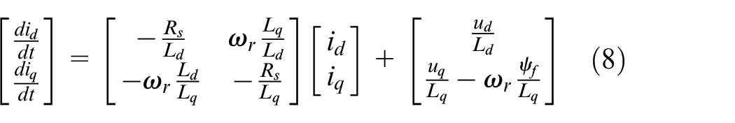
The IPMSM stator voltage equation is 7 :
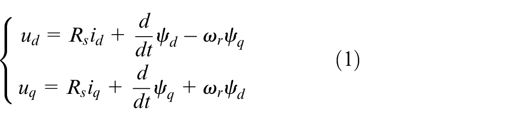
where
The equation for the magnetic chain is 7 :
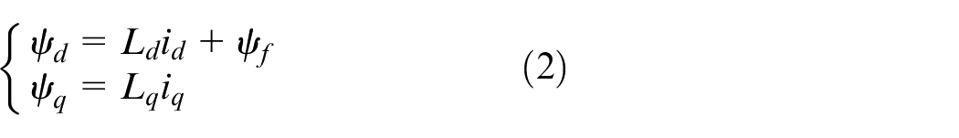
where
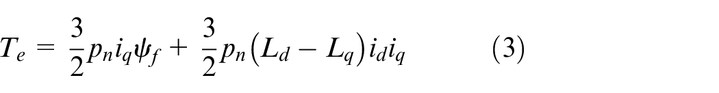
where
Design of full-order adaptive observer
Design approach for MRAS based on Popov’s super stability theory
The system studied by Popov can be equated to a nonlinear feedback system as shown in Figure 1.
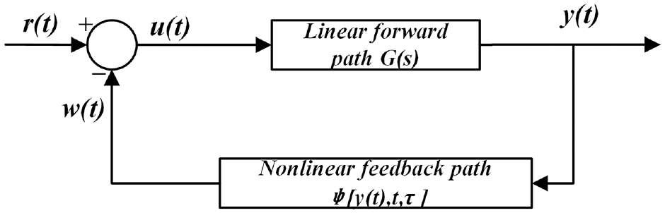
Block diagram of structure of non-linear feedback system.
When analysing the stability problem of the nonlinear feedback system shown in Figure 1, the general assumptions for the purpose of this study are
where

where
The necessary and sufficient condition for the asymptotic stability of the system is that the transfer function matrix

Based on the above presentation, the steps for applying Popov’s superstability theory to the design of MRAS are described as follows:
MRAS is equated to a non-linear feedback system consisting of a linear constant forward channel and a non-linear feedback channel.
The transfer function matrix
The non-linear feedback channel has to satisfy the Popov integral inequality.
Based on the original system, the final adaptive law is found.
Improved MRAS observer
We substitute equations (2) into (1) to obtain the mathematical model of the IPMSM in the
To obtain an adjustable model, the above equation is transformed into:
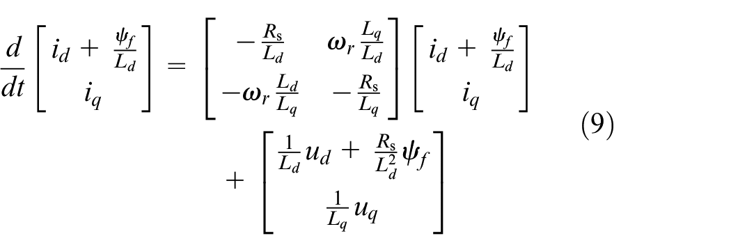
From equation (9), it can be deduced that:
where
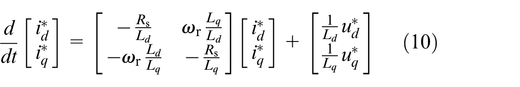
The rotation speed and current in equation (10) are replaced with estimated values to obtain an adjustable model:
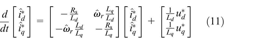
where
We let
where
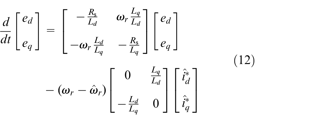
From equation (12), we obtain:
where
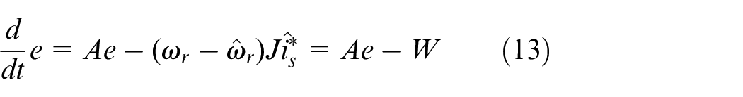
The error system created by equations (13) and (4) can be expressed as an equation of state in the form of:
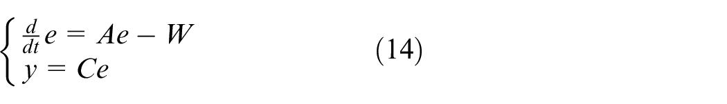
According to equation (14), a block diagram of the structure of the error system is obtained and shown in Figure 2. The solid line is a linear time-invariant (LTI) system. Since the relationship between the output quantity
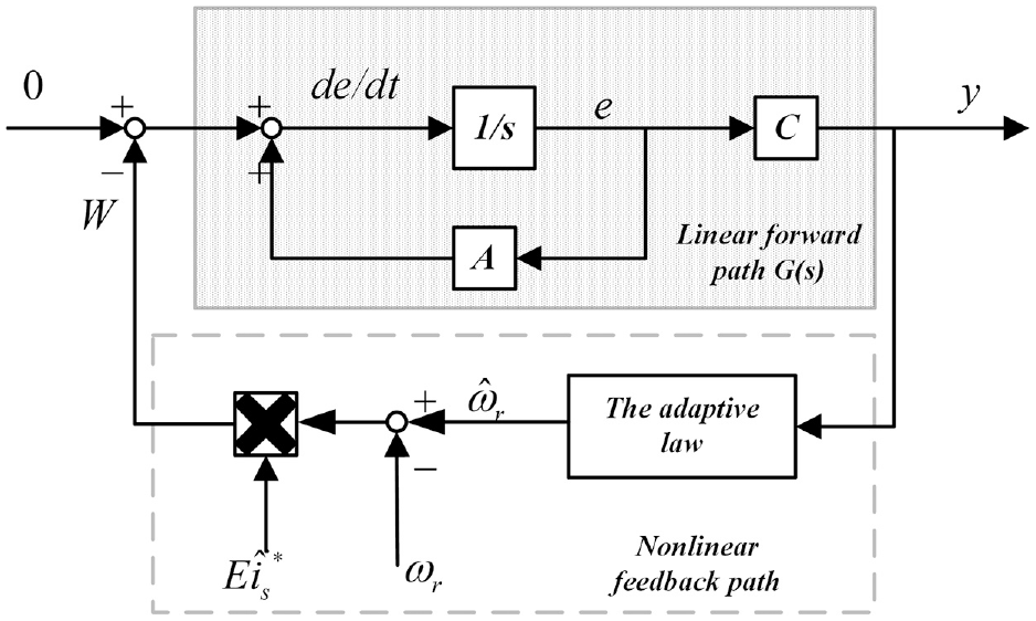
Block diagram of error system architecture.
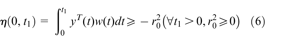
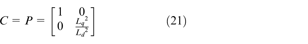
For the system shown above to be asymptotically stable, it is necessary to satisfy both equations (6) and (7). For the conventional MRAS, the linear compensation matrix
Selection of linear compensation matrix C
The transfer function matrix is shown in equation (14). A sufficient condition for the transfer function matrix
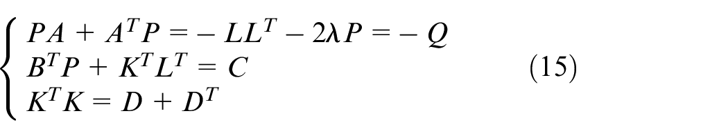
From equation (14), it can be seen that the
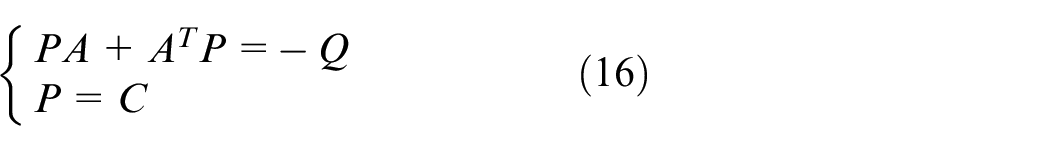
Therefore, by choosing the positive definite matrices
We prove the positivity of
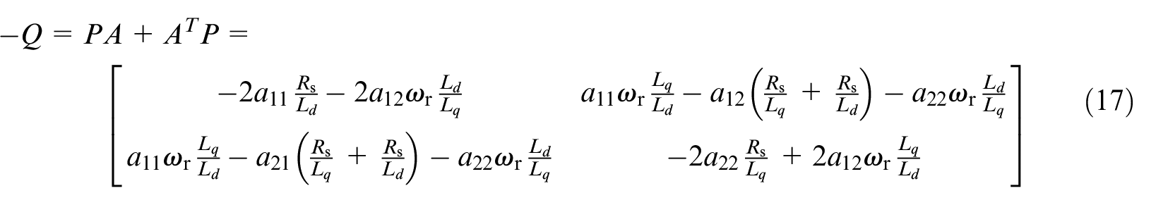
To fully consider the influence of the motor parameters
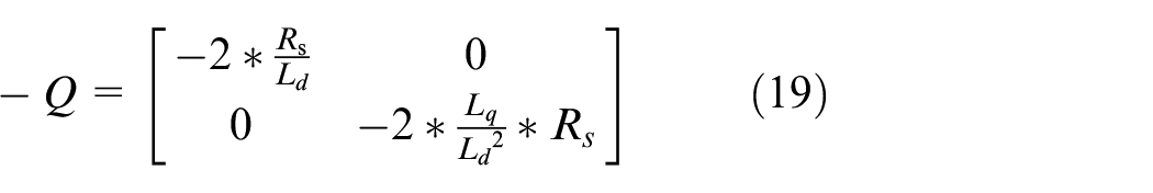
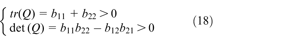
From equation (18), we obtain:
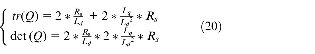
From equation (20), it is clear that
Thus, the assumption holds and it is desirable to have:
In this manner, it is guaranteed that
Design of adaptive law
After substituting
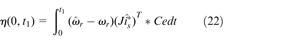
The MRAS speed estimation is in the form of a PI and will be expressed at
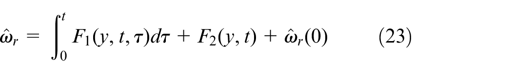
where
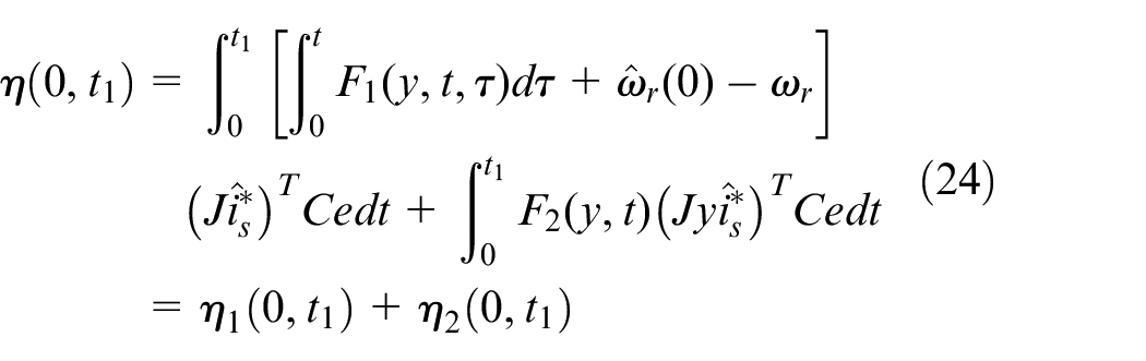
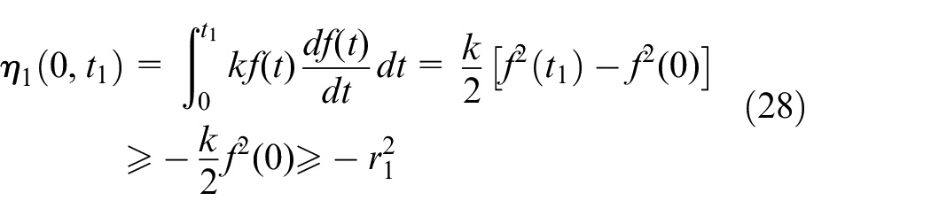
To make equation (24) valid, it is necessary to prove separately that:


For equation (24), we construct a function
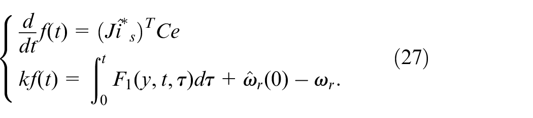
where
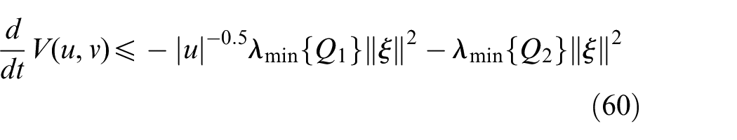
After taking the derivatives of both sides of equation (27), we obtain:
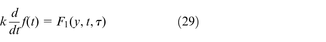
We substitute equation (27) into equation (29), and we obtain:

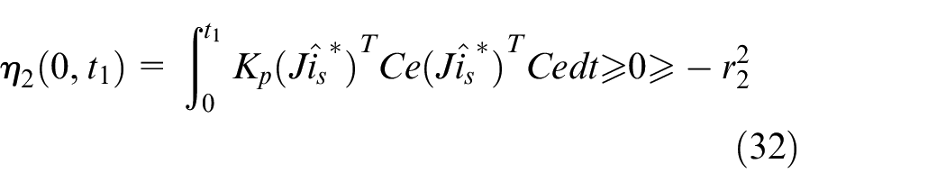
For equation (24), the inequality must hold if the product function is positive; thus, we take:

After substituting equation (31) into equation (26), we obtain:
After substituting equations (30) and (31) into equation (23), we obtain:
where
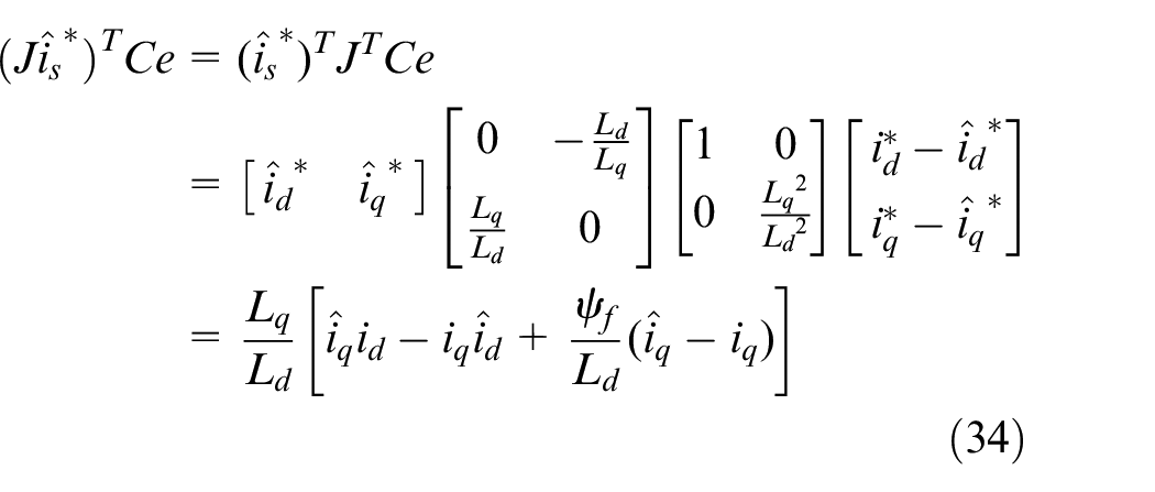
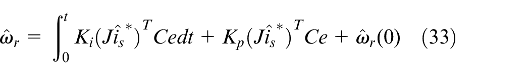
Thus, the new speed adaptive law is derived as follows:

In summary, the improved MRAS observer is shown in Figure 3
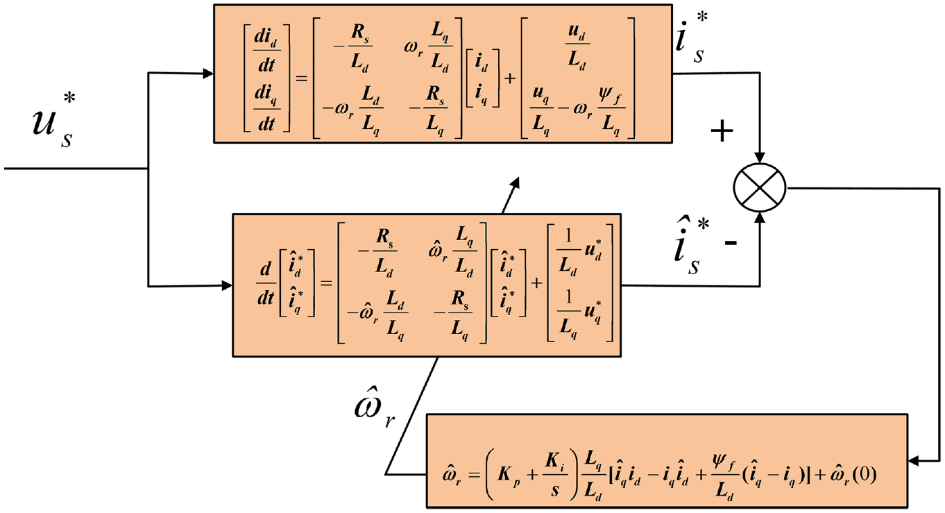
Improved MRAS observer.
MRAS speed observer with feedback correction term
To further improve the convergence speed of the output error between the reference and adjustable models in the above MRAS, this paper improves its structure by introducing the current error
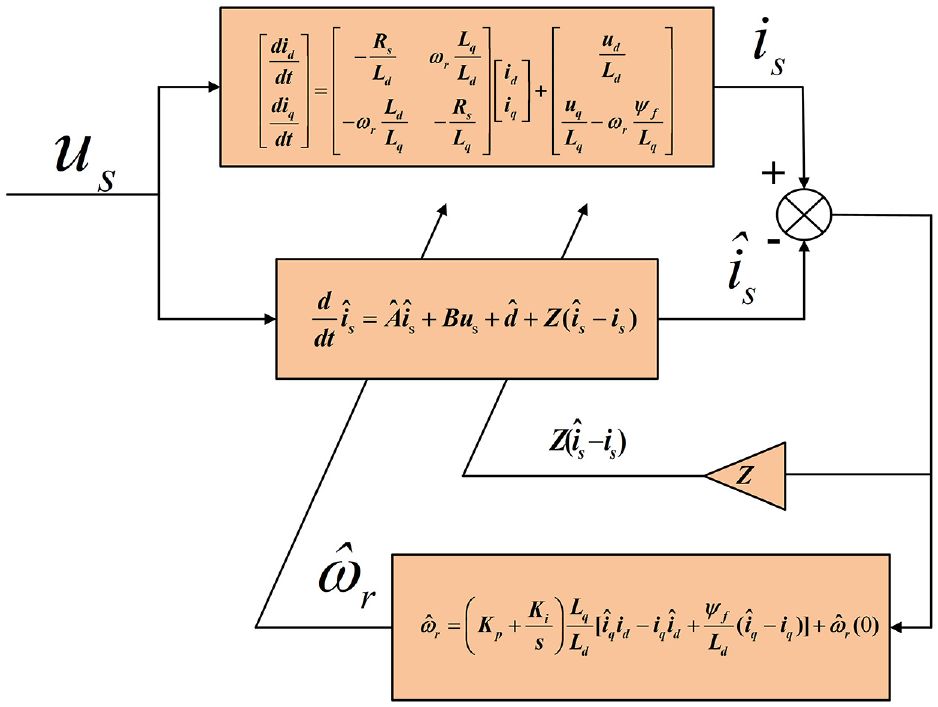
Block diagram of full-order adaptive observer structure.
First, we take equation (8) again as the reference model, and rewrite it as:
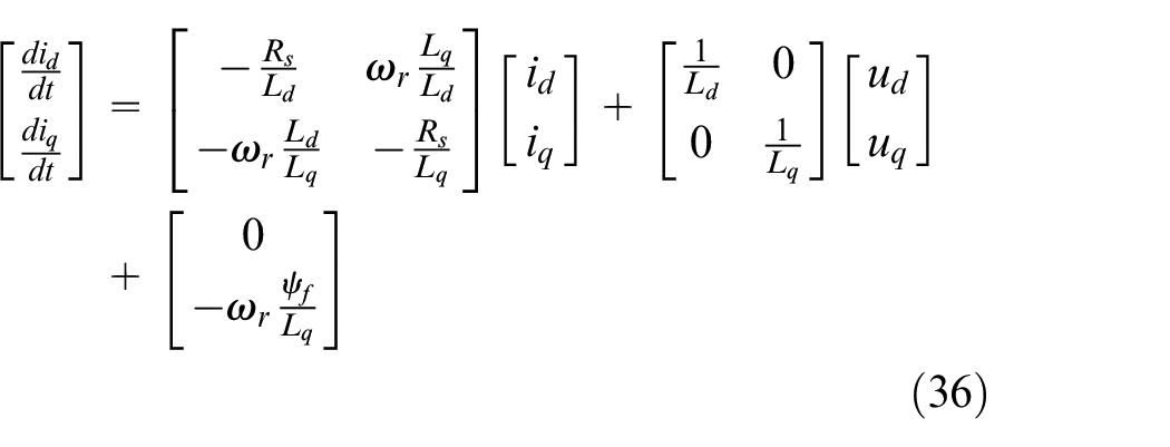
From equation (36), we obtain:
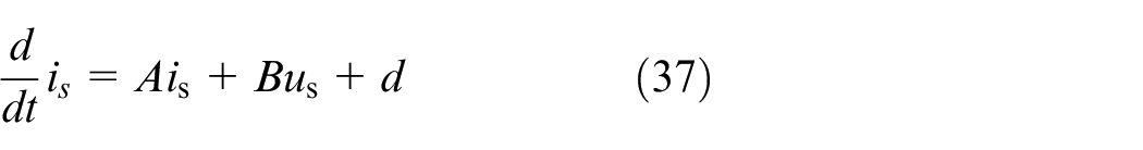
where
By replacing the corresponding variables in equation (36) with estimated values and adding the error correction matrix
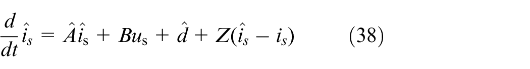
After subtracting equations (37) and (38) we obtain:
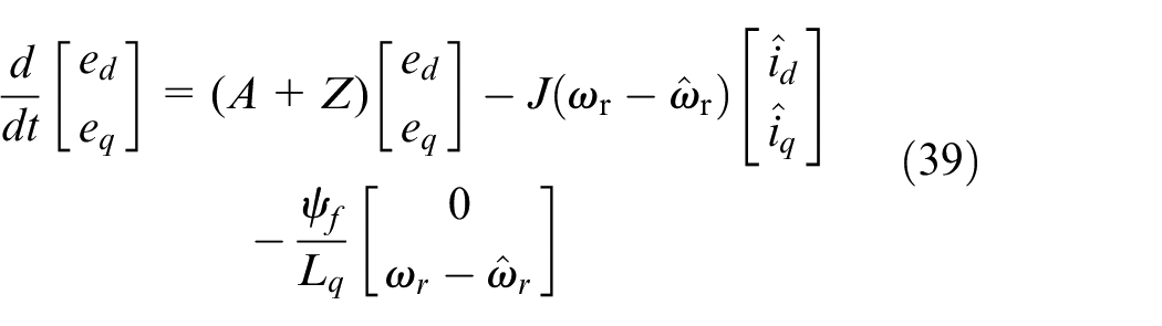
where
To meet the observer stability requirements, the feedback correction gain matrix
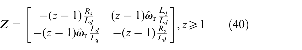
where
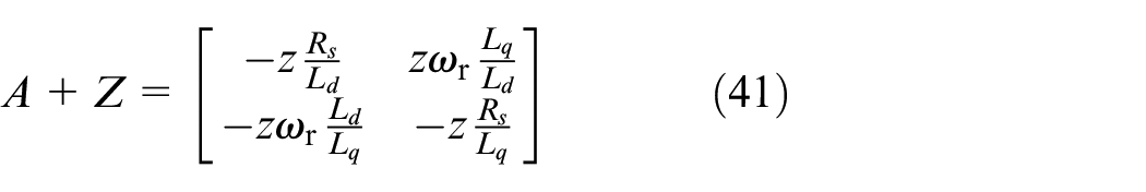
From equation (41), it can be seen that the main diagonal elements of the matrix are all negative, satisfying the stability requirement. Further, after comparing equations (12) and (39) in the matrices
Design of full-order adaptive observer based on novel fast super-twisting algorithm (NFSTA-AO)
Principle of second order sliding mode
Sliding mode control is simple in terms of structure and insensitive to external perturbations and changes in the system’s parameters, thus providing strong robustness. 31 The second order sliding mode not only retains the advantages of the traditional sliding mode, but also makes the trajectory of the uncertain control variable on the sliding mode surface approach the origin, and can be effectively controlled in a limited range, so as to weaken the chattering of the system. For a dynamic non-linear system,13,32 we have:
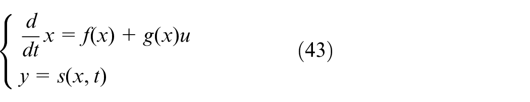
where
The first and second order derivatives of the sliding mode variables are as follows 32 :
To ensure the rigour of the theory, the following conditions apply 32 :
(1) If
(2)
(3) The normal number
And
(4) There are positive constants
Super-twisting algorithm (STA)
The super-twisting algorithm (STA) is a second-order sliding mode designed to eliminate jitter in a sliding mode system. It consists of a continuous function and a discontinuous differential with respect to the sliding mode variables, with the continuous function acting at the state arrival stage of the system. It does not require information on the derivatives of the sliding mode variables, avoiding the risk of introducing noise and disturbances and the control law is simpler to design. Its basic form is22,33:
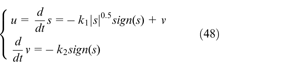
A sufficient condition for finite time convergence is 14 :
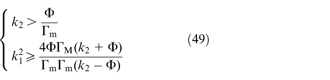
where
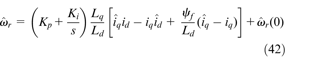
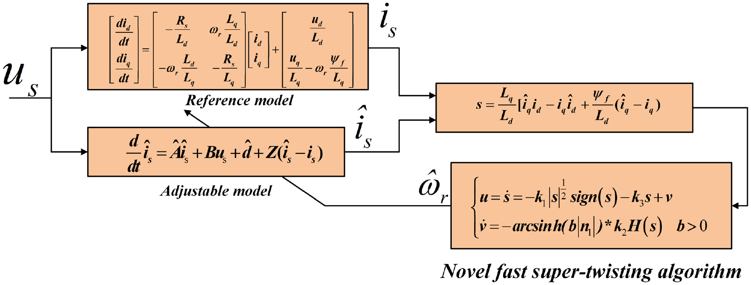
Design of NFSTA-AO
The adaptive mechanism in equation (42) is derived in the form of PI. When the motor parameters fluctuate, the accuracy of speed estimation will change, and the robustness is not strong. Therefore, it is necessary to replace the adaptive law in the substitution formula (42) with the STA approach law to construct a new speed observer. However, at low speeds, chattering will be more obvious with the STA observer. Thus, a novel super-twisting algorithm (STA) is needed to better suppress chattering.
Firstly, the FSTA can be constructed by adding a proportional sliding mode term to equation (48), which can effectively improve the convergence rate of the system; its expression is:
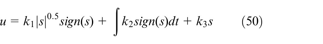
where
To better suppress the jitter of FSTA in the wide speed domain, reduce the tracking error, accelerate the convergence speed and enhance the dynamic following performance, the inverse hyperbolic sine function of the system state quantity
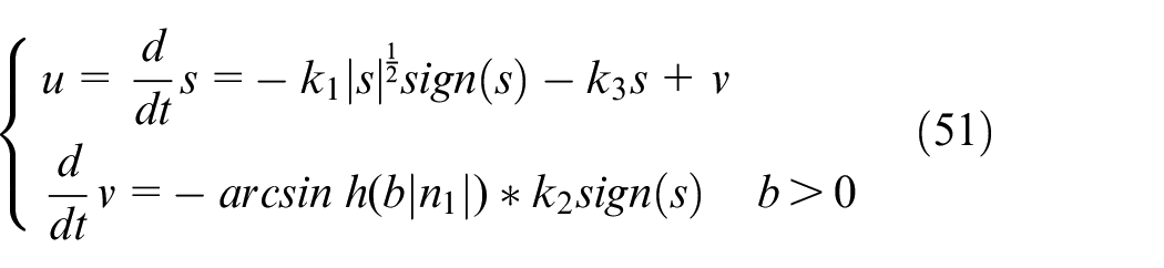
where
We choose the sliding surface
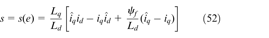
From equation (52), the derivation yields:
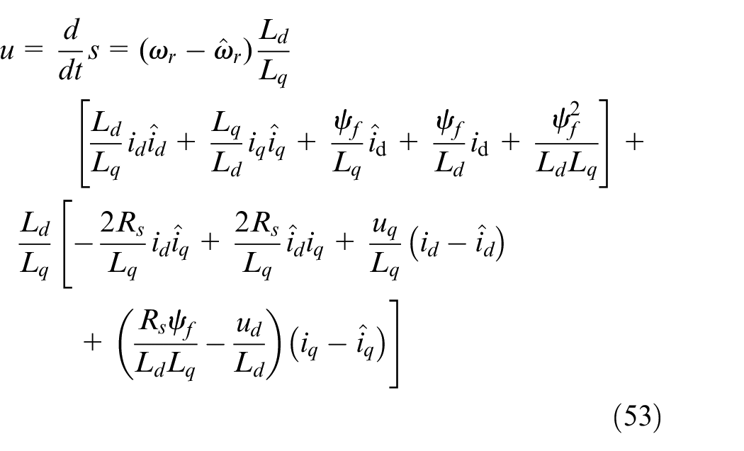
We obtain
According to the basic idea of sliding mode variable structure control, when the system enters the sliding mode (i.e. it enters the sliding mode surface), then
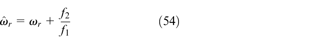
From equation (54), it can be seen that the equivalent velocity converges to the actual true velocity when the estimated current converges to the reference current, that is, when
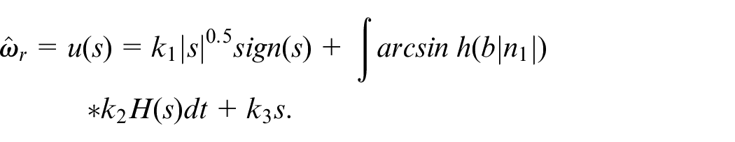
Based on the obtained switching function and equivalent speed, the speed observer is designed, where the above switching control law is used and the speed estimation expression is:
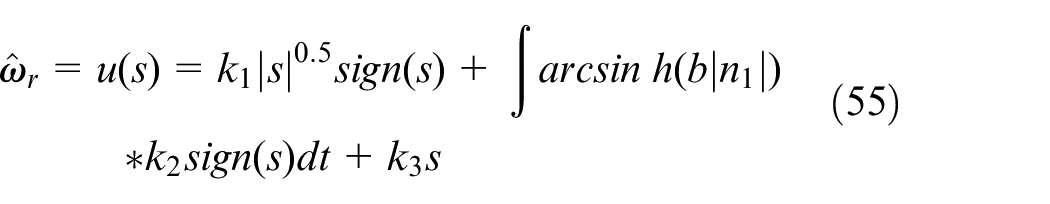
The use of a symbolic switching function (
Stability proof of the NFSTA
For the system shown in equation (51), we select the

where
We take
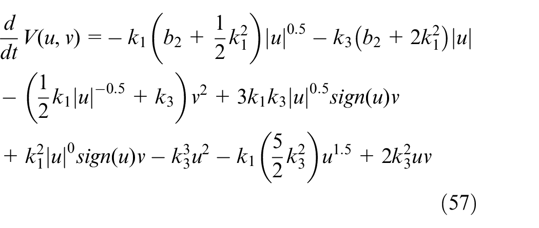
After transforming equation (57), the deformation yields:
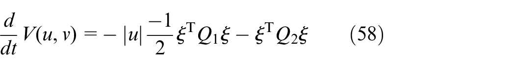
where
The parameters should meet the following conditions:
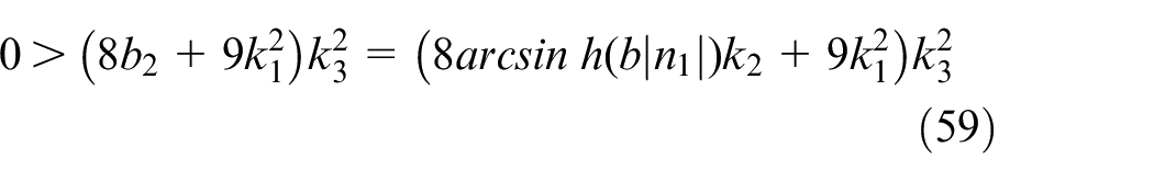
where
According to the stability theory of
Results and discussion
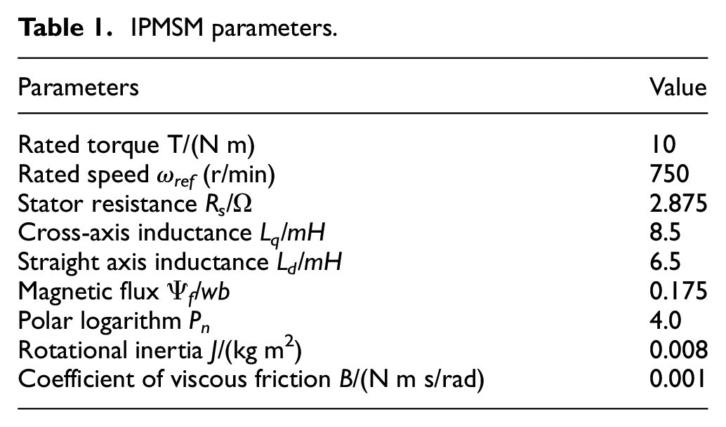
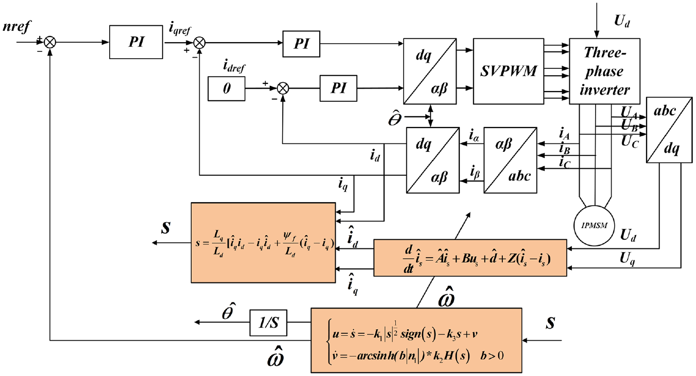
To verify the performance of the NFSTA-AO proposed in this paper, the IPMSM sensorless speed control system was built on the Matlab/Simulink platform; the overall block diagram of the system is shown in Figure 5. The various parameters of the motor are shown in Table 1. (nref is the given speed, nr is the estimated MRAS speed and nw is the response speed).
Block diagram of NFSTA-AO structure.
IPMSM parameters.
Test of system dynamic following
To verify the improvement of the NFSTA-AO estimation strategy proposed in this paper in terms of system dynamic following, the speed error of NFSTA-AO was compared with that of the model reference adaptive system observer based on super-twisting algorithm (STA-AO), 34 model reference adaptive system observer based on sliding mode (SM-MRAS) 35 and conventional MRAS. 11 Figures 6 and 7 show the error between the estimated speed and motor response speed for the four speed estimation strategies for different bandwidths of the given sinusoidal speed. There are two scenarios for the given sinusoidal speed described as follows: (i) the peak is 300 r/min, the trough is 200 r/min and the frequency is 5 Hz and (ii) the peak is 100 r/min, the trough is −100 r/min and the frequency is 15 Hz.
IPMSM speed control system without speed control.
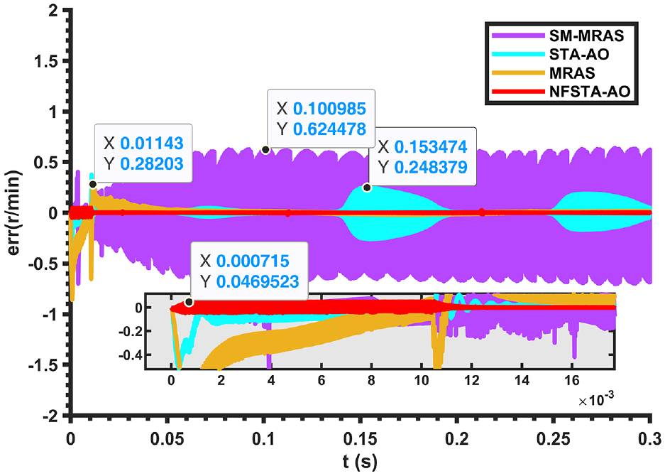
Error between estimated and actual speeds in the first sine case.
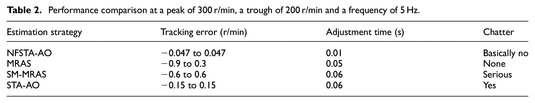
When the sinusoidal speed is given as the first case, the performance comparison is shown in Figure 8, and the performance is shown in Table 2. The STA-AO estimation strategy has a tracking error between −0.15 and 0.15 r/min, and the tracking error converges to zero after approximately 0.03 s. However, the estimated and response speeds are not stable under the influence of the given sinusoidal signal, and the dynamic following is poor. In contrast, the tracking error of the NFSTA-AO estimation strategy proposed in this paper is between −0.047 and 0.047 r/min, and the jitter of the estimated speed is well suppressed; it only takes 0.01 s for the estimated speed to basically follow the response speed strictly, and the dynamic following is very good.
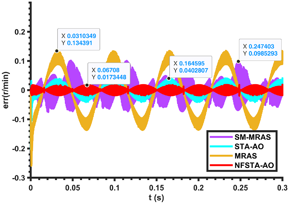
Error between estimated and actual speeds in the second sine case.
Performance comparison at a peak of 300 r/min, a trough of 200 r/min and a frequency of 5 Hz.
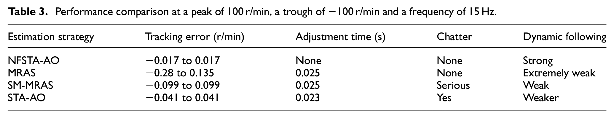
When the given sinusoidal speed is the second case, as shown in Figure 5, the performance comparison is shown in Table 3. The tracking error under the MRAS estimation strategy ranges from −0.28 to 0.135 r/min; it is larger at the moment of motor start, and after approximately 0.025 s, it is around 0. However, the tracking error fluctuates more and the dynamic following is poor. The tracking error under the SM-MRAS estimation strategy is between −0.099 and 0.099 r/min, and the jitter in the estimated speed is relatively large. The tracking error under the STA-AO estimation strategy is between −0.041 and 0.041 r/min, and although some of the jitter is suppressed, the tracking error fluctuates. In contrast, the tracking error of the NFSTA-AO estimation strategy proposed in this paper is in the range of −0.017 to 0.017 r/min, and the jitter of the estimated speed is well suppressed; the estimated speed can basically follow the response speed strictly at the start-up, and the dynamic following is very good.
Performance comparison at a peak of 100 r/min, a trough of −100 r/min and a frequency of 15 Hz.
It can be verified that the NFSTA-AO estimation strategy has strong dynamic following and can estimate the response speed faster and more accurately; this can effectively improve the response bandwidth of the system speed loop.
Test of system immunity
To verify the advantages of the NFSTA-AO estimation strategy in terms of resistance to external load disturbances, the speed error of NFSTA-AO was compared with that of STA-AO, SM-MRAS and MRAS through sudden load addition and removal at rated speed.
Figure 9 shows a comparison of the speed tracking error for four speed estimation strategies at rated speed with a sudden load of 15 N m at 0.1 s. The performance comparison is shown in Table 4. The estimated speed under the MRAS estimation strategy tracked up to the response speed after 0.05 s. The tracking error was 0.7 r/min at the instant of sudden load application and tracked up to the response speed after 0.0055 s. The jitter of the estimated speed under the SM-MRAS estimation strategy was obvious, with tracking errors of −1 to 1 r/min, and the speed error did not change much at the instant of sudden load application. The STA-AO estimation strategy has an estimated speed of 0.004 s to track the upper response speed; its tracking error is 1 r/min at the moment of sudden load application, and the estimated speed tracks the upper response speed after 0.004 s. In contrast, the NFSTA-AO estimation strategy has a tracking error of ±0.05 r/min, and the tracking error is essentially zero after 0.03 s; its speed tracking error is 0.3 r/min at the moment of sudden load application, but the instantaneous estimated speed follows the response speed strictly.
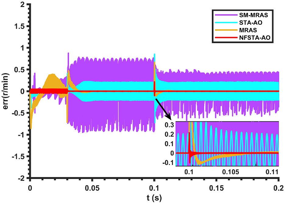
Error between estimated and actual speeds when a sudden load is applied.
Performance comparison for sudden load addition.
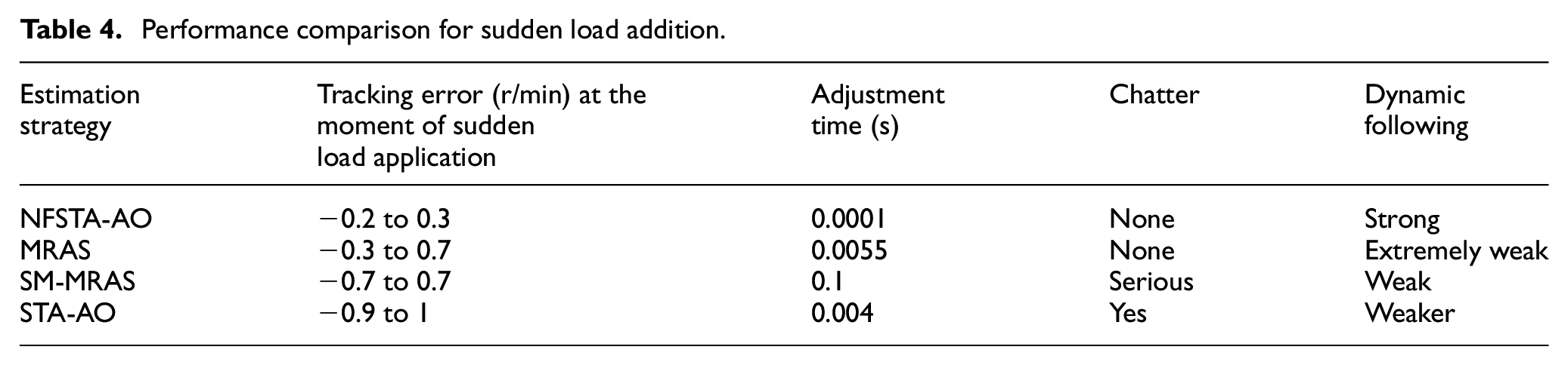
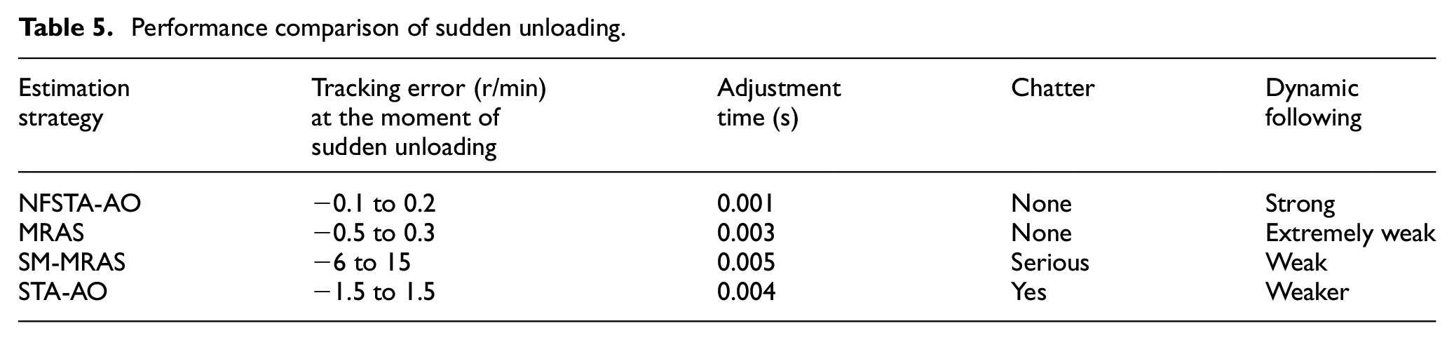
Figure 10 shows a comparison of the speed tracking error for the four speed estimation strategies when running with a load of 15 N m at rated speed and a sudden unloading of 5 N m at 0.2 s. The performance comparison is shown in Table 5. Under the MRAS estimation strategy, the tracking error is 0.5 r/min at the moment of sudden unloading, and the speed is estimated to track up to the corresponding speed after 0.003 s. In the STA-AO estimation strategy, the tracking error is 0.6 r/min at the moment of sudden unloading, and the speed is estimated to track the corresponding speed after 0.004 s. For the NFSTA-AO estimation strategy, the tracking error is 0.2 r/min at the moment of sudden unloading, and the speed is estimated to track the corresponding speed after 0.001 s.
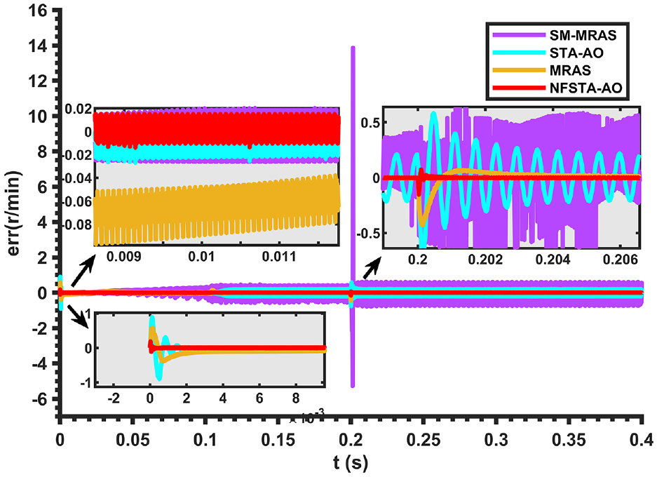
Error between estimated and actual speeds when suddenly unloading a load.
Performance comparison of sudden unloading.
It can be verified that the NFSTA-AO estimation strategy is highly immune to disturbances, allowing the speed estimates to converge to the corresponding actual values more quickly and with less fluctuation in the estimation error. Moreover, the steady-state recovery time of the tracking error is significantly reduced compared to the other three control strategies.
Test of system robustness
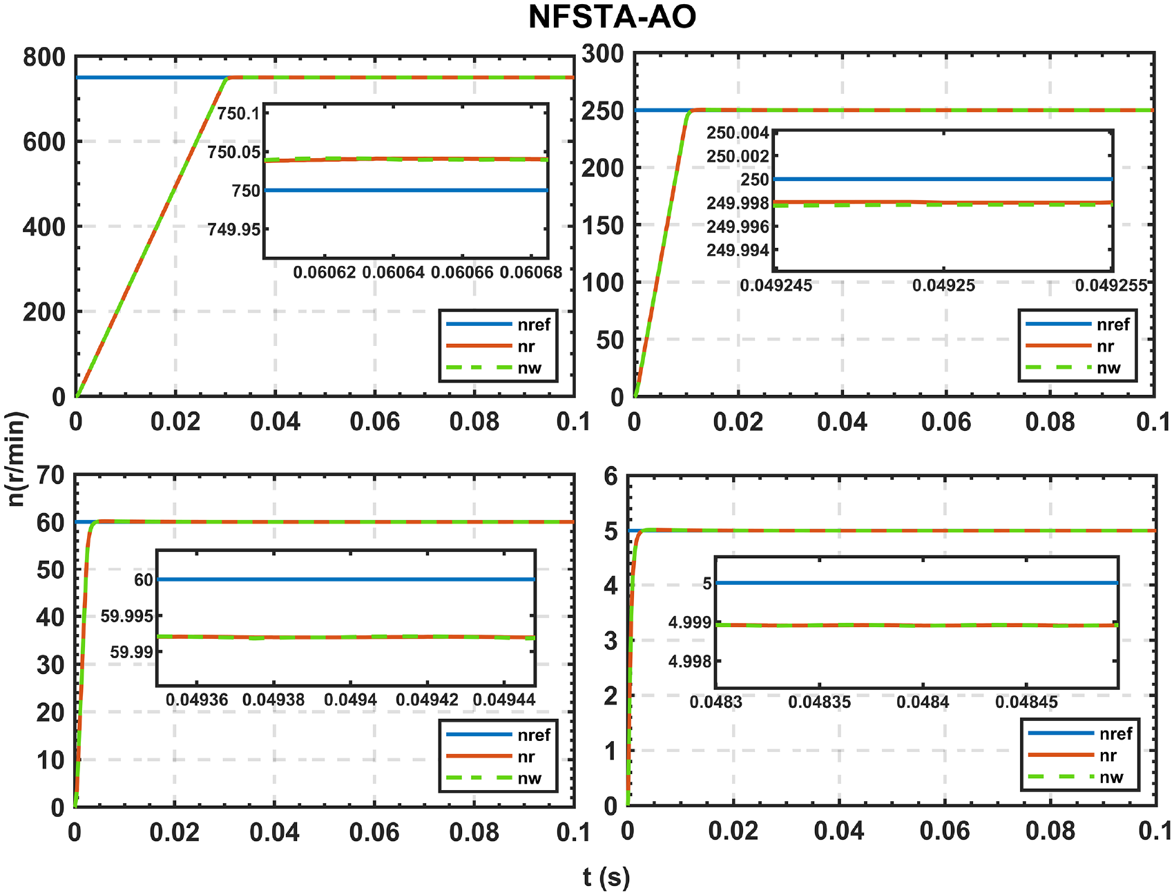
To further verify that the NFSTA-AO estimation strategy has better robustness, the performance of the four estimation strategies is simulated and compared when the IPMSM parameters are regenerated, as shown in Figures 11 to 14. The performance comparisons are shown in Tables 6 and 7. A total of three sets of simulations were carried out to simulate the motor parameter ingress. In the first set of tests, the stator resistance value Rs of the IPMSM was set to 1.2 times the original value for operation at rated speed, taking into account the effect of temperature variations on the stator resistance value. In test group 2, the Rs of the IPMSM was set to 0.8 times the original value for operation at rated speed. To further validate the robustness of the STA-AO based estimation strategy proposed in this paper, the d and q axis inductances of the IPMSM were changed to 0.8 times the original value for the third comparison test at rated speed.
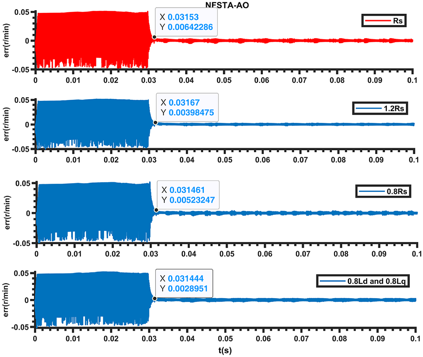
NFSTA-AO error comparison between estimated and actual speeds for parameter ingress.
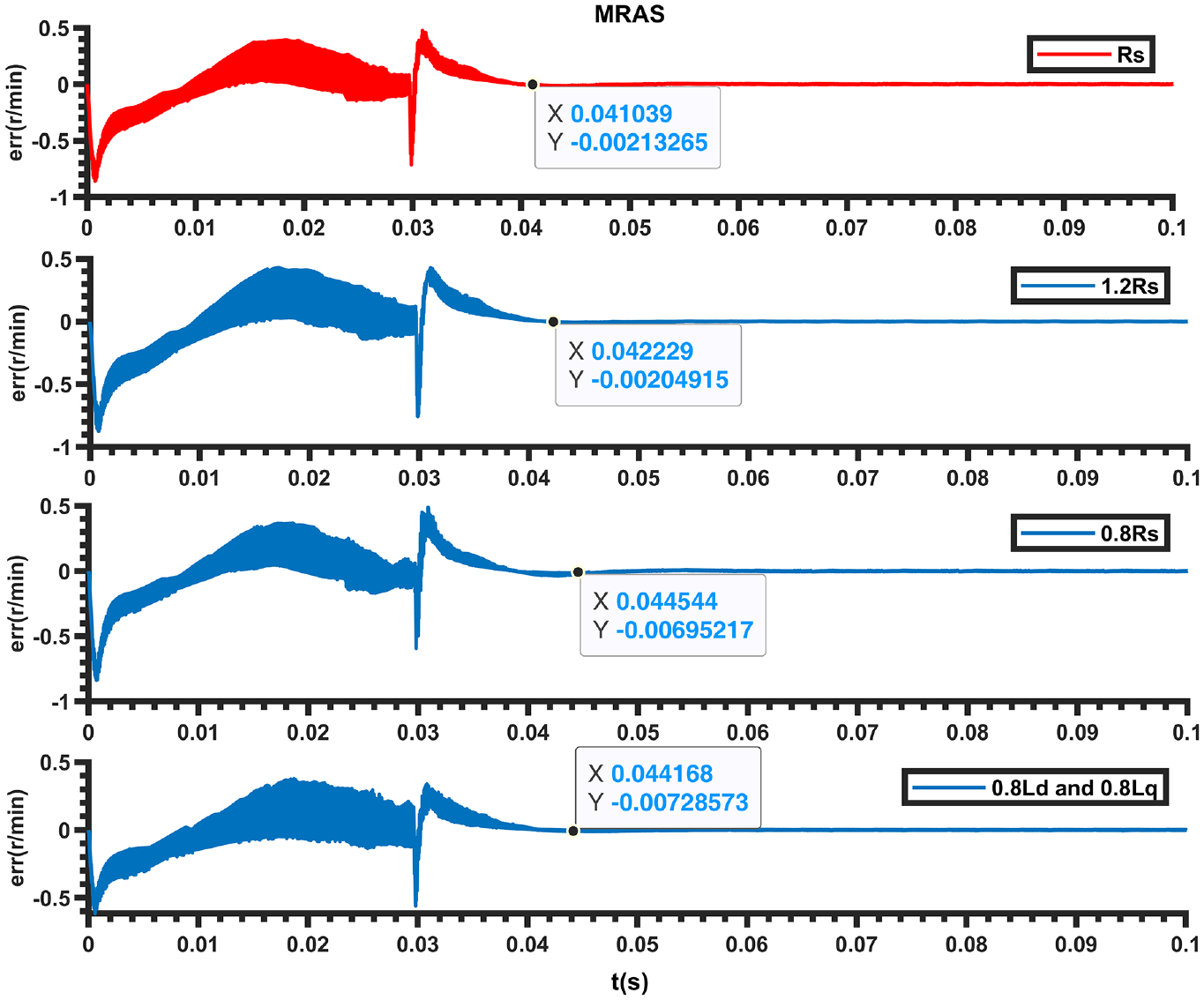
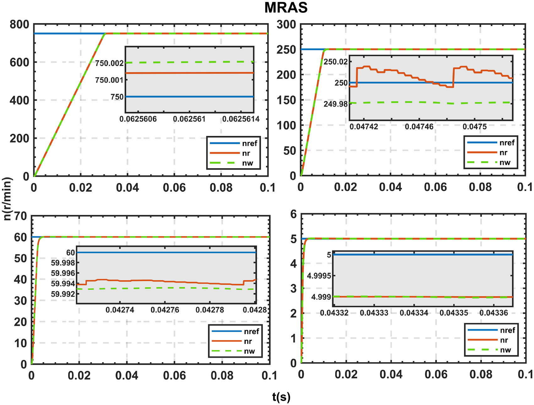
MRAS error between estimated and actual speeds for parameter ingress.
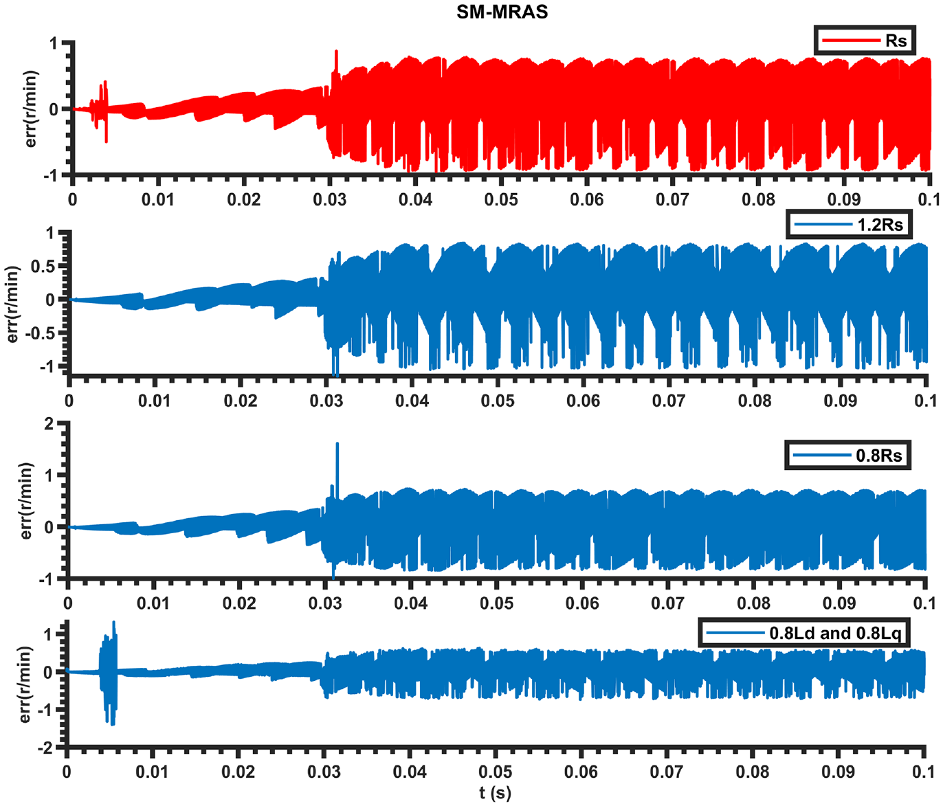
SM-MRAS error comparison between estimated and actual speeds for parameter ingress.
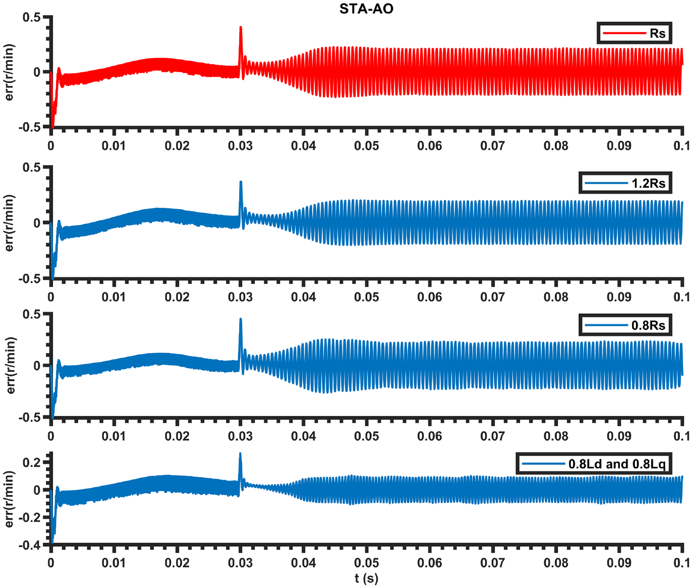
Error comparison between estimated and actual speeds for STA-AO for parameter ingress.
Comparison of regulation times (s) after reaching a given speed during motor parameter ingress.
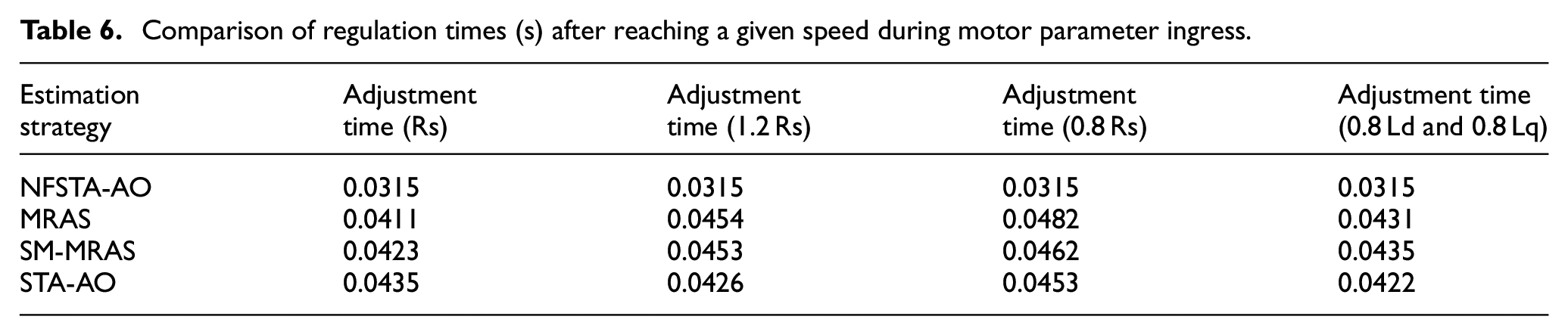
Comparison of maximum tracking errors (r/min) for motor parameter ingress.
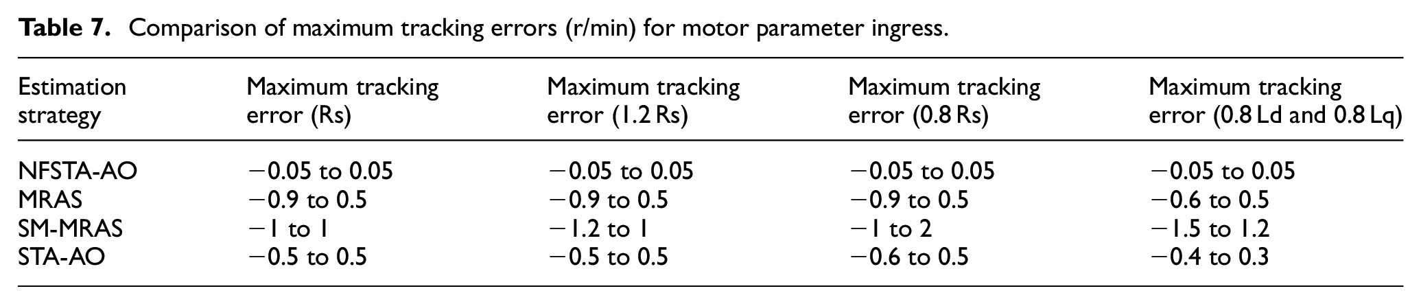
The MRAS estimation strategy takes 0.004 s for different cases to converge to the corresponding estimated value when the motor parameters are perturbed, with a tracking error of −0.9 to 0.5 r/min; after reaching the given speed, it takes approximately another 0.015 s for different cases to bring the tracking error close to zero. The tracking error increases slowly as the response speed approaches the given speed, and becomes stable at the maximum value after the given speed is reached. In the NFSTA-AO estimation strategy, the speed estimation converges to the corresponding response speed with a tracking error of ±0.05 r/min during the start-up phase, while the tracking error converges to zero after the given speed is reached.
It can be verified that the NFSTA-AO estimation strategy is more robust than the other three estimation strategies and has less impact on the accuracy of speed estimation when parameter ingestion occurs, which in turn makes the IPMSM operation smoother.
Test of wide speed domain
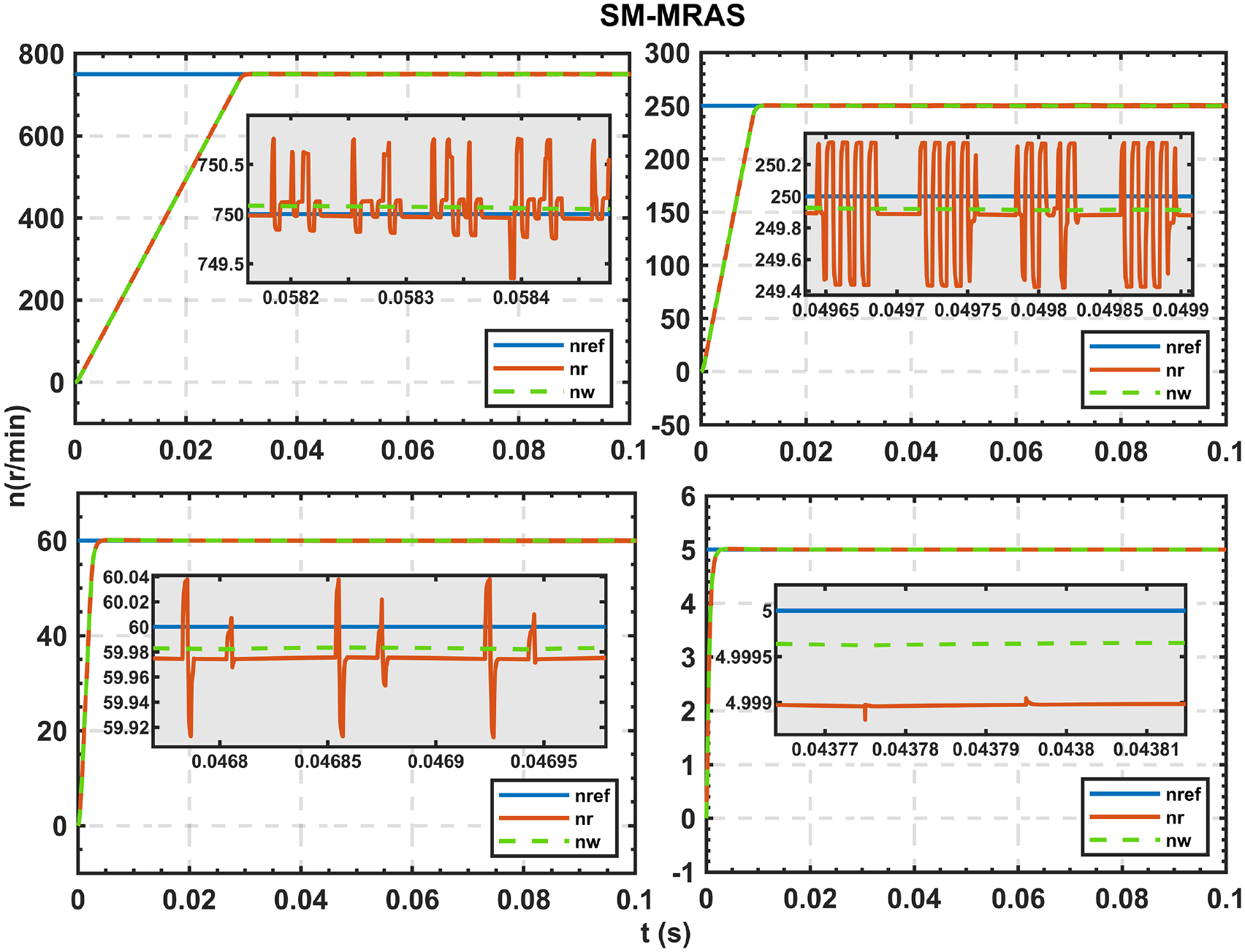
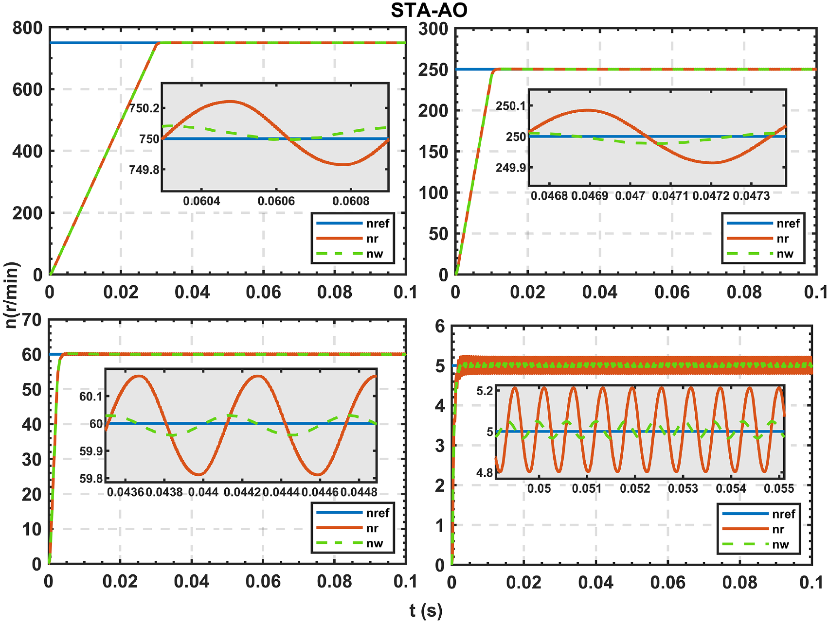
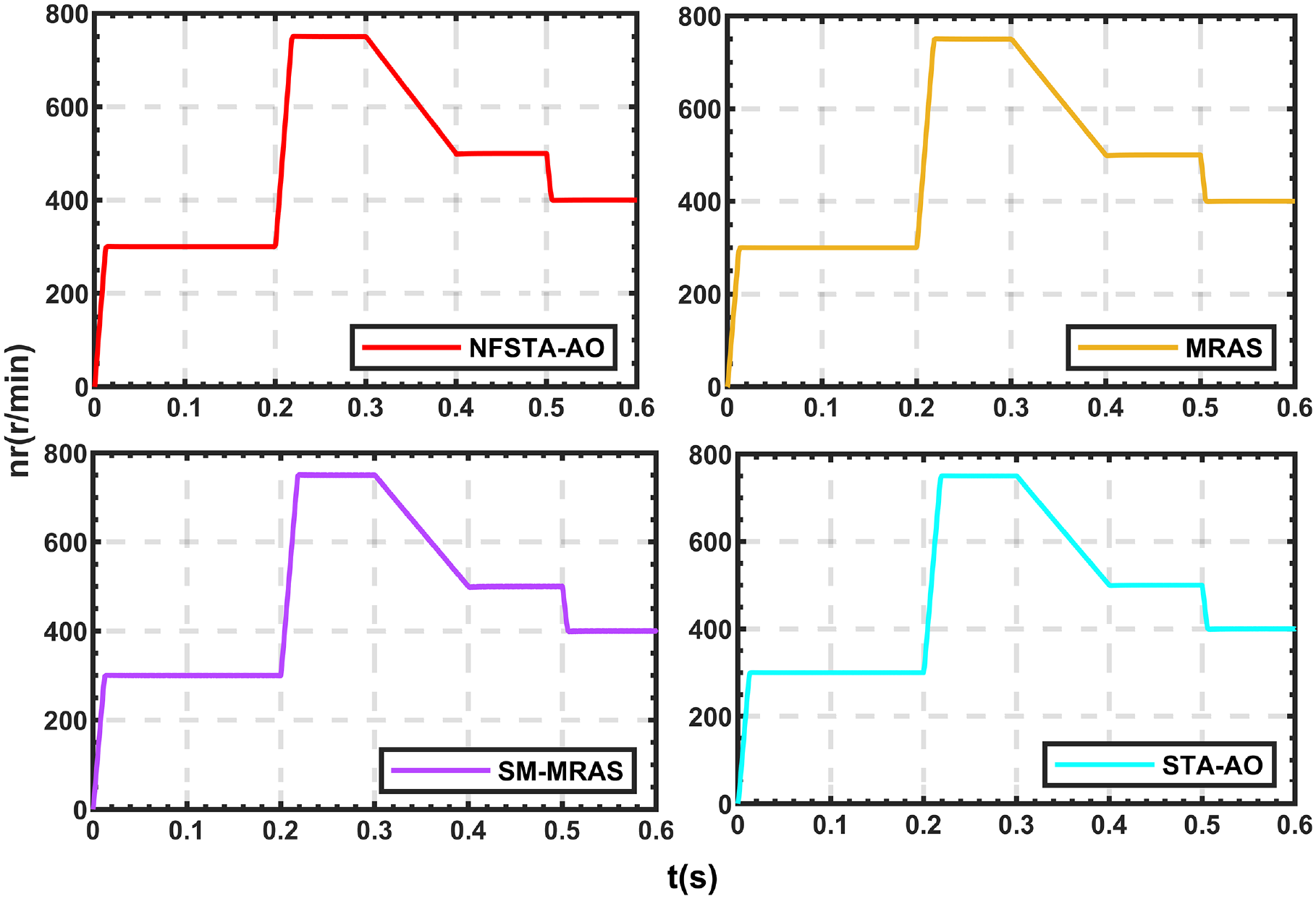
To verify that the NFSTA-AO estimation strategy has better speed estimation accuracy in the wide speed domain of the system, the high and low estimated speeds under the NFSTA-AO estimation strategy were compared with those of the STA-AO, SM-MRAS and MRAS estimation strategies. The nref, nw and nr for the four estimation strategies at 5, 65, 250 and 750 r/min speeds are shown in Figures 15 to 18. The performance comparison is shown in Table 8.
Comparison of given, estimated and response speeds for different speed intervals (NFSTA-AO).
Comparison of given, estimated and response speeds for different speed intervals (MRAS).
Comparison of given, estimated and response speeds for different speed intervals (SM-MRAS).
Comparison of given, estimated and response speeds for different speed intervals (STA-AO).
Performance comparison (r/min) over a wide speed range.
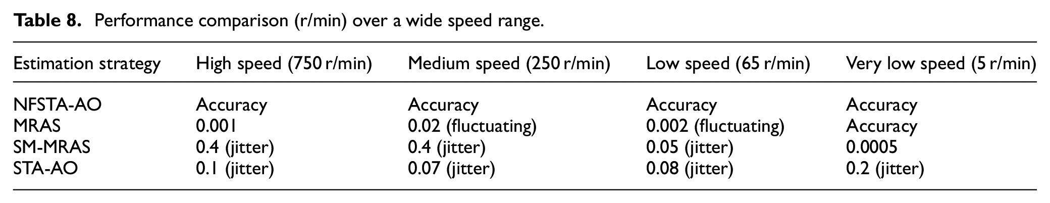
The MRAS estimation strategy has a tracking error of 0.002 r/min and a fluctuation in the estimated speed, while the SM-MRAS estimation strategy has a significant jitter in the estimated speed with a tracking error of 0.04 r/min. The STA-AO estimation strategy suppresses the jitter, but the jitter is still present, especially at low speeds, making the response speed also jitter. With the NFSTA-AO estimation strategy, the estimated speed can strictly follow the response speed at different speed segments, and there is no jitter or fluctuation in the estimated speed.
It can be verified that the NFSTA-AO estimation strategy is better than the other three estimation strategies; it can suppress the jitter caused by the sliding mode variable structure, achieve high performance and high accuracy control of IPMSM, as well as realise the wide speed domain without static difference estimation.
Test of sudden speed change under constant load torque
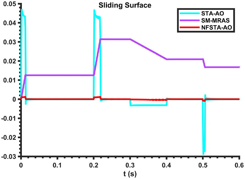
To verify the stability of the NFSTA-AO estimation strategy during sudden changes in speed, the estimated speed and tracking error under the NFSTA-AO estimation strategy were compared with those of the STA-AO, SM-MRAS and MRAS estimation strategies, as shown in Figures 19 and 20. The performance comparisons are shown in Table 9. Figure 21 shows the comparison of the sliding surface for the three estimation strategies for sudden changes in speed. The motor is started at no load, initially at a given speed of 300 r/min, stepping from the given speed to the rated speed at 0.2 s and dropping from the rated speed ramp (with a slope of −1250) to 500 r/min at 0.3 s and stepping down to 400 r/min at 0.5 s.
Comparison of estimated rotational speed for the four estimation strategies for sudden changes.
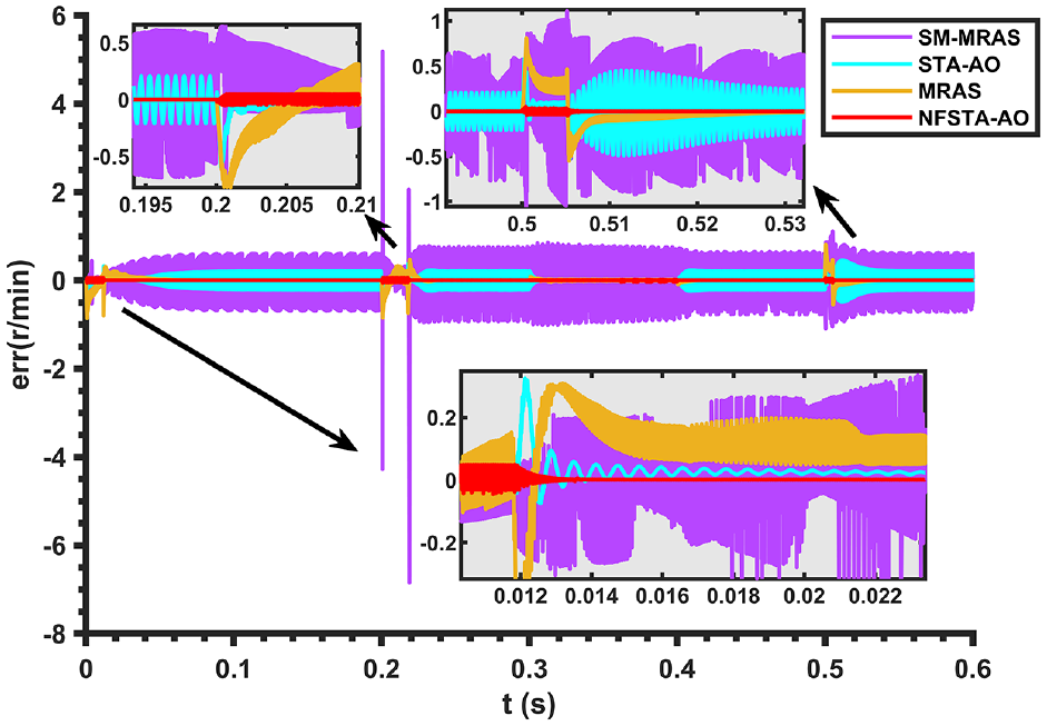
Comparison of tracking error of the four estimation strategies for sudden changes in speed.
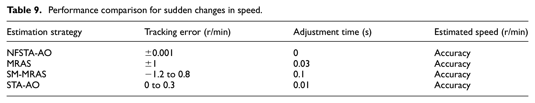
Performance comparison for sudden changes in speed.
Sliding surface ratios for the three estimation strategies for sudden changes in speed.
As it can be seen from Figure 19, all four estimation strategies can achieve accurate estimation of the response speed. From Figure 20, the MRAS estimation strategy has a tracking error of −1 to 1 r/min and a regulation time of 0.03 s. The SM-MRAS estimation strategy has little effect on the sudden change in speed, with a maximum tracking error of −1.2 to 0.8 r/min. The STA-AO estimation strategy has a tracking error of 0 to 0.3 r/min and a regulation time of 0.01 s at the moment of sudden change in speed. In contrast, the NFSTA-AO estimation strategy can always strictly follow the response speed when the speed changes abruptly, which has better dynamic characteristics than the other three estimation strategies. As it can be seen from Figure 21, although the estimated speed of SM-MRAS can follow the given speed, the sliding surface never converges to zero. STA-AO has a relatively large jitter on the sliding surface when the speed changes abruptly. In contrast, the sliding surface of NFSTA-AO is always close to zero. This proves that NFSTA-AO has better convergence in finite time.
Conclusions
In this paper, a full-order adaptive observer based on a novel fast super-twisting algorithm (NFSTA-AO) is proposed to address the problem that the traditional model reference adaptive system (MRAS) can only achieve speed discrimination and estimate speed with low accuracy in a certain speed range. To extend the speed discrimination interval of MRAS, a new linear compensation matrix is designed instead of the conventional unit matrix using Popov’s super stability theory. To further improve the speed and accuracy of convergence of the error between the adjustable and reference model outputs in the MRAS, an error correction link is introduced in the adjustable model and a full-order adaptive observer is constructed so that the output of the adjustable model is continuously corrected in a feedback manner. Moreover, to improve the accuracy of the full-order adaptive observer, resistance to load disturbance and robustness when the motor parameters are perturbed so that the estimated speed is approaching faster the response speed, the approach law of the novel fast super-twisting algorithm (NFSTA) was introduced to replace the adaptive law of the full-order adaptive observer, and the NFSTA-AO was constructed. This allows the NFSTA-AO to combine the advantages of both algorithms.
The simulation results verify that the NFSTA-AO observer proposed in this paper has lower tracking error, better immunity and robustness compared to the MRAS, SM-MRAS and STA-AO. Also, it suppresses better the sliding mode jitter, and has higher estimation accuracy and better dynamic following performance. Thus, it provides a new method for studying the speed estimation strategy of high performance permanent magnet synchronous motor speed control systems without speed sensors.
Footnotes
Declaration of conflicting interests
The author(s) declared no potential conflicts of interest with respect to the research, authorship, and/or publication of this article.
Funding
The author(s) disclosed receipt of the following financial support for the research, authorship, and/or publication of this article: This work is supported by the Jilin Province Science and Technology Development Plan Project under Grant 20210204116YY.