
Abstract
Relative coupling control (RCC) structure is widely used for multi-motor speed synchronization control. To improve the performance of multi-motor synchronous control, artificial bee colony (ABC) algorithm is developed and applied for enhancing RCC structure. The RCC structure optimized by the ABC algorithm is called the RCC-ABC structure. In the RCC-ABC structure, the ABC algorithm optimizes both the fixed compensation factor in the speed compensator and the parameters of the PID controller acting as a tracking controller. Simulation experiments based on a four-motor system are conducted to validate the efficiency of the RCC-ABC structure. Simulation results show that the RCC-ABC structure has better synchronization and tracking performance compared to the RCC structure.
Keywords
Introduction
Multi-motor synchronous control has been widely used in various fields of industry.1–3 Synchronization control structures and tracking controllers for multi-motor systems are not only the key to achieving high precision synchronous control but also directly affect the reliability of industrial systems and product manufacturing quality.
At present, the research work on multi-motor speed synchronous control is mainly focused on synchronous control structures and tracking controllers. The main synchronous control structures are master-slave control (MSC) structure, 4 cross-coupling control (CCC) structure, 5 adjacent cross-coupling control (ACCC) structure, 6 and relative coupling control (RCC) structure. 7 The most popular synchronous control structure used for multi-motor systems is RCC. To further promote the reliability and effectiveness of RCC, Shi et al. 8 presented an improved relative coupling control structure (IRCC) that introduced an additional speed controller to treat all the motors as an entity. Zhu et al. 9 proposed a mean relative coupling control (MRCC) for multi-motor systems. In MRCC, the average speed was used to replace the speed difference between each motor, which simplified the structure of the RCC structure and reduced the calculation of the system. Based on MRCC, Wang et al. 10 proposed a decoupled control structure with synchronous control of the inner loop and following control of the outer loop. Its effectiveness was verified by practical experiments. One major issue in RCC is that the motor synchronization performance is affected by the fixed compensation factors, which are related to the motor’s rotational inertia. Therefore, when the load torque varies significantly, the multi-motor system fluctuates greatly and is even unstable.
The tracking accuracy of multi-motor systems is closely related to tracking controllers. In this regard, many controllers, such as proportional integral derivative (PID), 11 sliding mode control (SMC), 12 fuzzy control, 13 neural network control, 14 have been proposed. However, the multi-motor system is a nonlinear, multivariable, and strongly coupled control object. More optimized tracking controllers are needed to further boost the tracking accuracy.
Karaboga and Akay 15 developed the ABC algorithm as one of the bio-inspired optimization methods. Due to its ease of structure, implementation, and well-organized exploitation and exploration techniques, the ABC algorithm has demonstrated remarkable performance on a variety of actual tasks. 16 Many applications have been developed based on the ABC algorithm, including wireless sensor networks, 17 big data, 18 image processing, 19 deep learning, 20 and so on. For existing bio-inspired optimization algorithms, the ABC algorithm remained the top competitor. The literature 21 provides a comprehensive overview of recent advancements and real-world applications. The use of optimization algorithms to solve real-world problems has become commonplace.22–24 However, it is worth noting that the application of the ABC algorithm to RCC has rarely been reported.
In this study, we aimed to address these questions by introducing the ABC algorithm in the RCC structure to improve the synchronization performance and tracking performance. Besides, the significant contribution of this study is that a relative coupling control optimized by ABC (RCC-ABC) structure for multi-motor systems using ABC algorithm is proposed.
The rest of the paper is organized into four sections. An introduction is presented in Section 1, followed by the proposed structure, and simulation analysis and validation in Sections 2 and 3, respectively. Section 4 concludes the proposed work.
The proposed structure
Traditional RCC structure
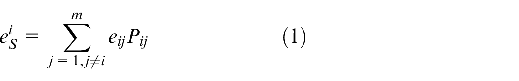
Traditional RCC mainly consists of speed compensators and tracking controllers, the structure of which is presented in Figure 1. In Figure 1, eSi is the speed compensation from the speed compensator i, and it can be expressed by the following equation
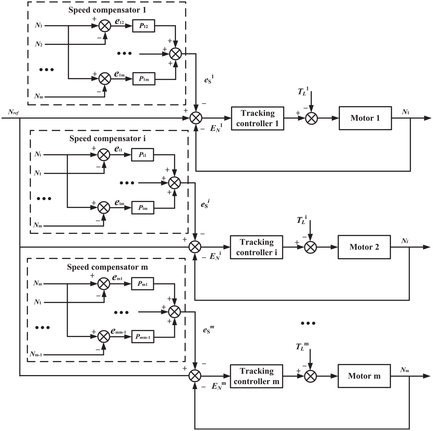
The RCC structure.
where m represents the total number of motors, Pij is a fixed compensation factor, and it can be given by
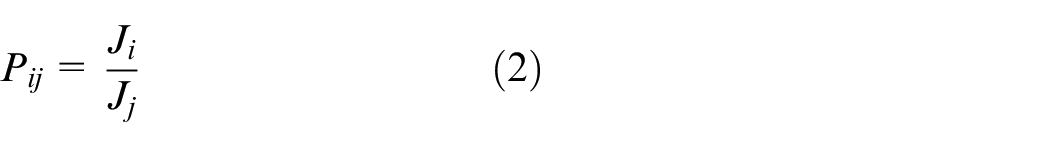
where Ji is the rotational inertia of motor i, Jj is the rotational inertia of motor j. From Figure 1, the input ENi to the tracking controller can be expressed as

where Nref is the motor reference speed.
Speed compensators dynamically distribute the speed compensation among the motors according to the operating status of each motor. Tracking controllers enable motors to reach the desired speed accurately. The synchronization of multiple motors requires the convergence of errors among the motors, the following conditions must be satisfied
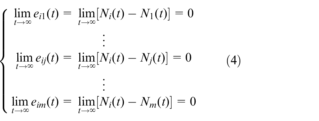
where ei1 is speed error between motor i and motor 1, Ni is the speed of the motor i, N1 is the speed of the motor 1, eij is speed error between motor i and motor j, Nj is the speed of the motor j, eim is speed error between motor i and motor m, Nm is the speed of the motor m, m represents the total number of motors.
The RCC optimized by the ABC (RCC-ABC)
The RCC-ABC proposed in this paper incorporates the ABC algorithm to improve its synchronization performance and tracking performance, and its structure is shown in Figure 2. In the RCC-ABC, the ABC algorithm optimizes the parameters of two kinds. One is the fixed compensation factor (Pi1,…, Pim) and the other is the gain (kPi, kIi, and kDi) of the PID controller that is used for tracking controller.
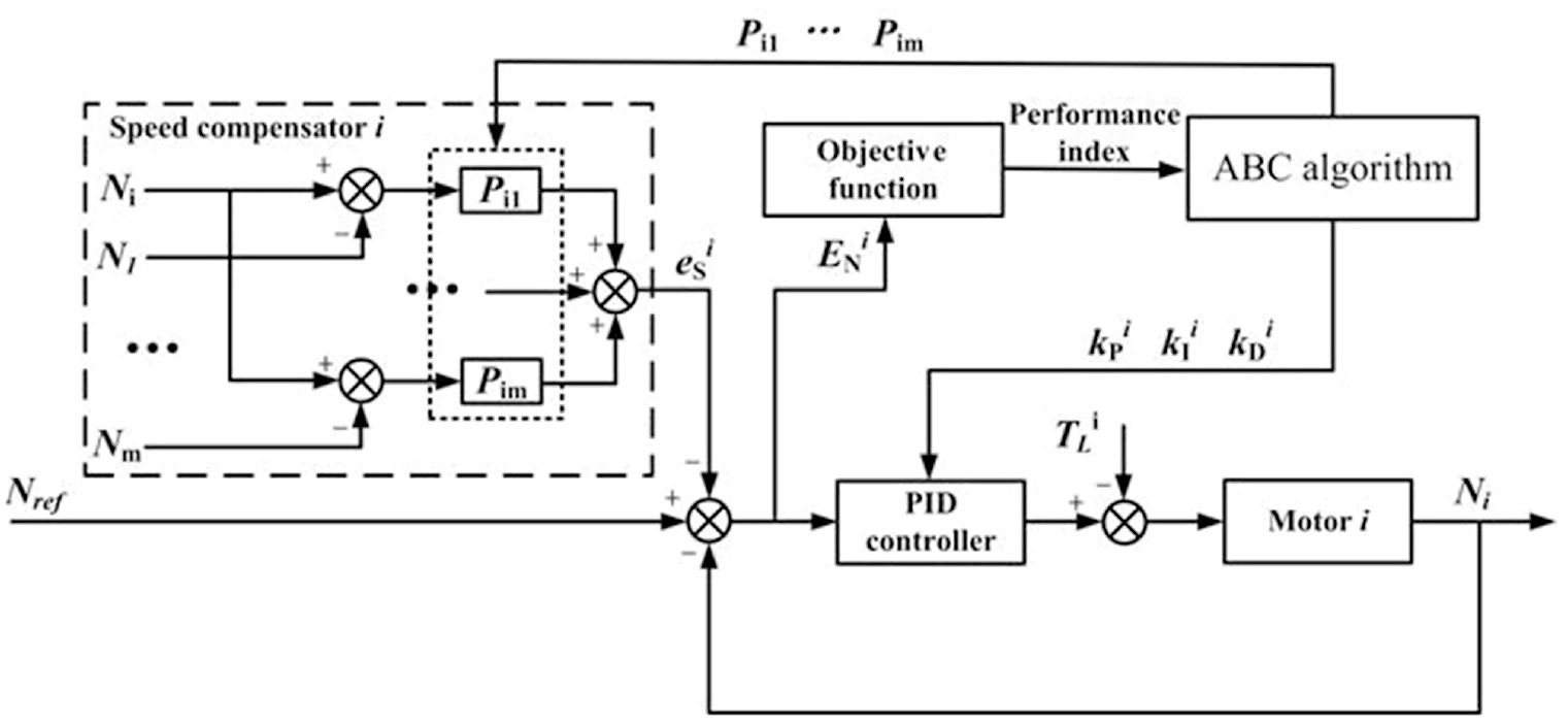
The RCC-ABC structure.
In the ABC algorithm, the bees are divided into three types: employed bees, follow bees, and scout bees. A search phrase is set for one type of bees, namely: employed bees phase, follow bees phase, and scout bees phase. 15 In the beginning, the algorithm uses a random initialization method to generate the initial population, and its generation method is shown in the following equation (5)

where i = 1,…,SN, n = 1,…,D. SN represents the population size, D represents the dimension of the problem, rand(0,1) is a random number between 0 and 1,
In the stage of the employed bees, the employed bees search for a food source according to equation (6)

where k∈(1,…, SN) and k ≠ i; j∈(1,…, D).
In the follow bees stage, the follow bees use the information that the employed bees share, to select the food source according to the probability calculated by the following equation (7).
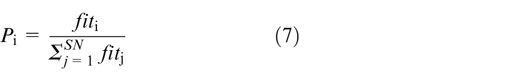
where fiti represents the fitness value of the ith food source.
In the scout bee stage, a food source, if its quality that has not been getting better several times in a row (“limit” is denoted as the maximum number of times), will be discarded. The following bee searching for this food source will turn into the scout bee. In the ABC algorithm, the food source corresponds to the candidate solution of the optimization problem, and the quality of the food source represents the good or bad candidate solution.
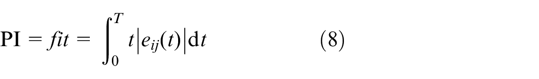
In this paper, performance index (PI) as the fitness value is defined as follows:
Comparing the RCC-ABC with the RCC, the differences lie in three aspects.
Difference in structure: In the RCC, there are no ABC algorithms and the motor speed errors are only fed back into the tracking controllers. The RCC-ABC owns additional ABC algorithms, which makes the parameters in the system more flexible. Motor speed errors are not only fed back into the tracking controller but also into the ABC algorithm through the objective function, which provides the performance index for the ABC algorithm.
Difference in synchronized information: When applying the RCC, there is no distinction of synchronization error between motors. Regardless of the change in synchronization error, Pij remains constant. The RCC-ABC instead emphasizes synchronized information through the ABC algorithm to adjust the value of parameter Pij according to motor speed error.
Difference in tracking capability: The RCC uses PID controllers or sliding mode controllers as tracking controllers. The parameters of both controllers are not optimal, and the tracking capability of both controllers needs to be further improved. In the RCC-ABC, the tracking controllers are PID controllers of which three gains are precisely tuned by the ABC algorithm. The tracking capability of the tracking controller is optimized.
The flowchart in Figure 3 summarizes the steps of the ABC algorithm to find the optimal parameters [Pi1,…, Pim, kPi, kIi, and kDi] of the RCC. In the next section, the RCC-ABC will be further analyzed by simulation.
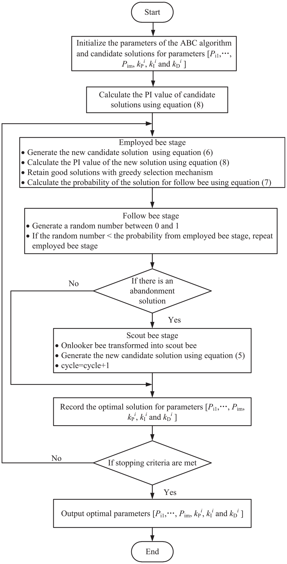
The flowchart of the ABC algorithm to find the optimal parameters.
Simulation analysis and validation
The RCC-ABC is verified from two aspects: one is synchronization performance and the other is tracking performance. Synchronization is affected by sudden changes in load torque TLi, so it is verified from no change in load torque TLi and sudden changes in load torque TLi. The tracking performance is affected by the reference speed Nref, so it is simulated at different reference speed Nref.
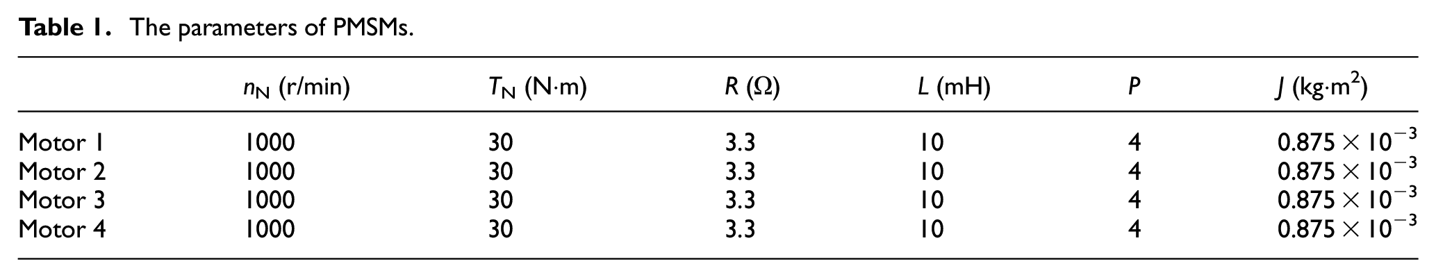
The modeling and simulation of the four-motor speed synchronous system are carried out by using MATLAB/Simulink. The motors used in the simulation are four permanent magnet synchronous motors (PMSMs). The simulation parameters of PMSMs are shown in Table 1. The modeling of PMSM can be found in the literature. 9
The parameters of PMSMs.
The population size and limit affect the performance of the ABC algorithm. First, a test was done to find the appropriate population size, and results are shown in Table 2. In Table 2, synchronous error E ij , is the speed error between the motor i and motor j; Mean is the mean value of the synchronous error; Std is the standard deviation of the synchronous error.
Test results for different population size.
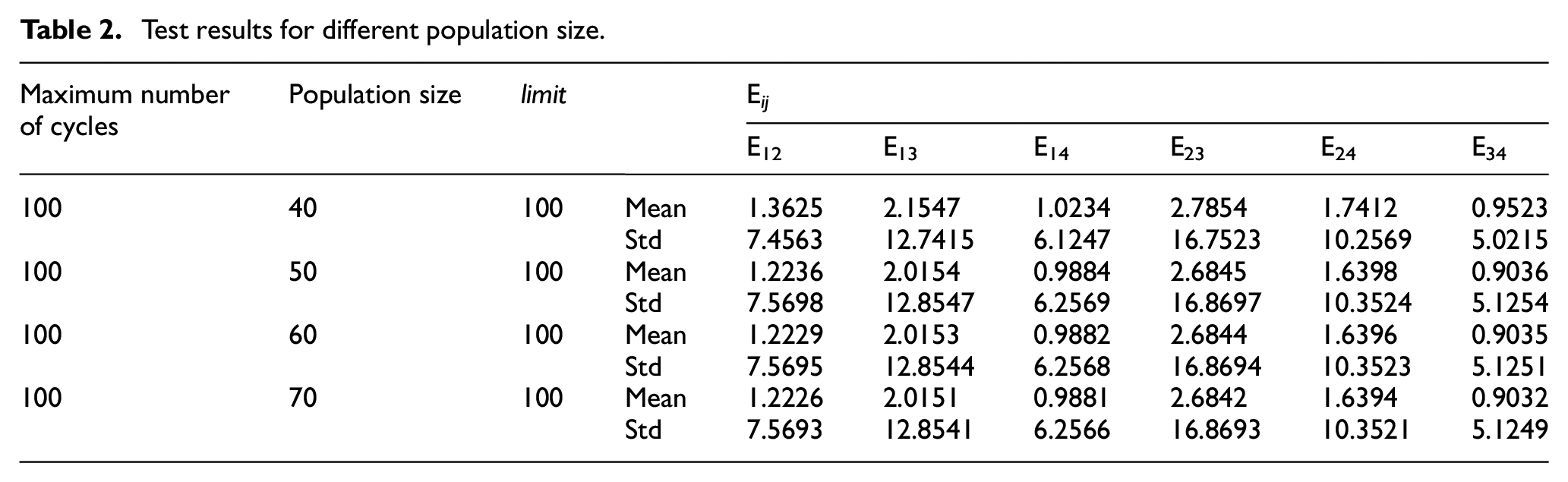
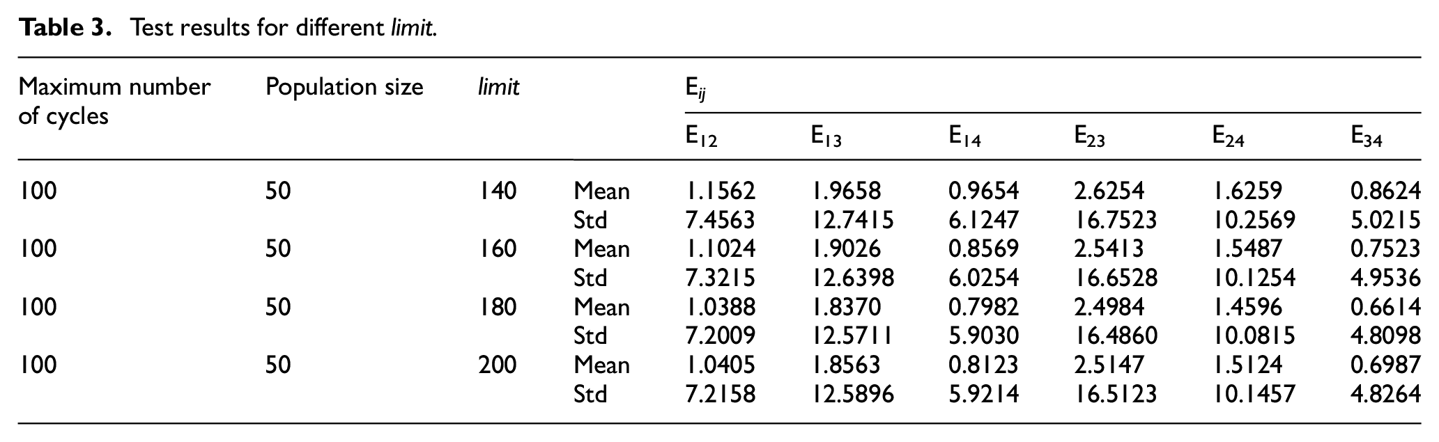
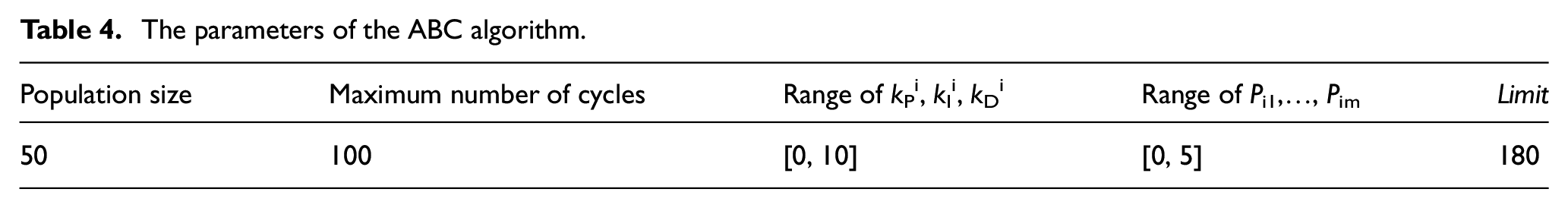
From Table 2, in terms of Mean and Std, population size of 50 is better than population size of 40, and almost tied with population size of 60 and 70. But in terms of running speed, population size of 50 is faster than population size of 60 and 70. As a result, population size of ABC algorithm was set to 50 for all experiments. The other test was performed to determine the optimal value of the limit, and results are shown in Table 3. From Table 3, it can be observed that Mean and Std are obtained as minimum at limit for 180. Therefore, the limit is set to 180 for all experiments. The final parameters of the ABC algorithm are presented in Table 4.
Test results for different limit.
The parameters of the ABC algorithm.
Synchronization simulation
No sudden change in load torque
Let the given reference speed Nref = 1000 r/min. The load torques TL1, TL2, TL3, and TL4 of the four motors were 9, 11, 13, and 15 N/m, respectively. Simulation time t = 0.4 s. In RCC and RCC-ABC, PID controllers were selected as tracking controllers, and its three parameters kp, ki, and kd are set to 5.6, 0.3, and 1.1, respectively. A comparison of the RCC-ABC and the RCC was made. The simulation results are presented in Figure 4. In Figure 4, synchronous error E ij , is the speed error between the motor i and motor j. In addition.
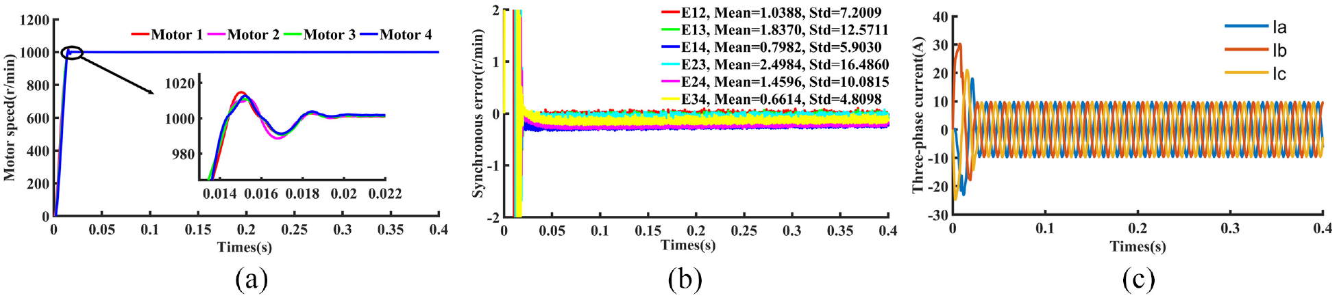
RCC-ABC and PID controller used in no changes in load torque: (a) motor speed, (b) synchronous error curve, and (c) variation of three-phase current of motor 1.
From Figures 4 and 5, the motor responses of the RCC-ABC look more closely than that of the RCC (Figures 4(a) and 5(a)), while the two types of compensators do not show much difference in the synchronous errors curve. From Figures 4(b) and 5(b), it is also shown that the difference between both methods in terms of Mean and Std of the synchronization errors are not significant. The reason for the observation is that RCC-ABC and RCC are applied in the absence of sudden changes in load torque TLi.
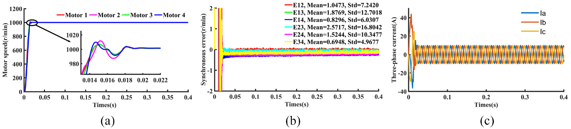
RCC and PID controller used in no changes in load torque: (a) motor speed, (b) synchronous error curve, and (c) variation of three-phase current of motor 1.
Sudden change in load torque
The reference speed Nref and simulation time t were also set to 1000 r/min and 0.4 s respectively. In the RCC, PID controllers were also selected as tracking controllers. Sudden change in load torque TLi was divided into four cases:
Case 1: The initial load torque TL1 of motor 1 was 9 N/m, which changed abruptly to 18 N/m after 0.2 s; The load torques TL2, TL 3 , and TL4 of motor 2, motor 3, and motor 4 remain 11, 13, and 15 N/m, respectively.
Case 2: The initial load torque TL1 and TL2 of motor 1 and motor 2 were 9 and 11 N/m, respectively, which changed abruptly to 18 and 22 N/m after 0.2 s respectively; the load torques TL3 and TL4 of motor 3 and motor 4 remain 13 and 15 N/m, respectively.
Case 3: The initial load torque TL1, TL2, and TL3of motor 1, motor 2, and motor 3 were 9, 11, and 13 N/m, respectively, which changed abruptly to 18, 22, and 26 N/m after 0.2 s, respectively; the load torques TL4 of motor 4 remain 15 N/m.
Case 4: The initial load torque TL1, TL2, TL3, and TL4of motor 1, motor 2, motor 3, and motor 4 were 9, 11, 13, and 15 N/m, respectively, which changed abruptly to 18, 22, 26, and 30 N/m after 0.2 s, respectively. The simulation results for the four cases are shown in Figures 5–8.
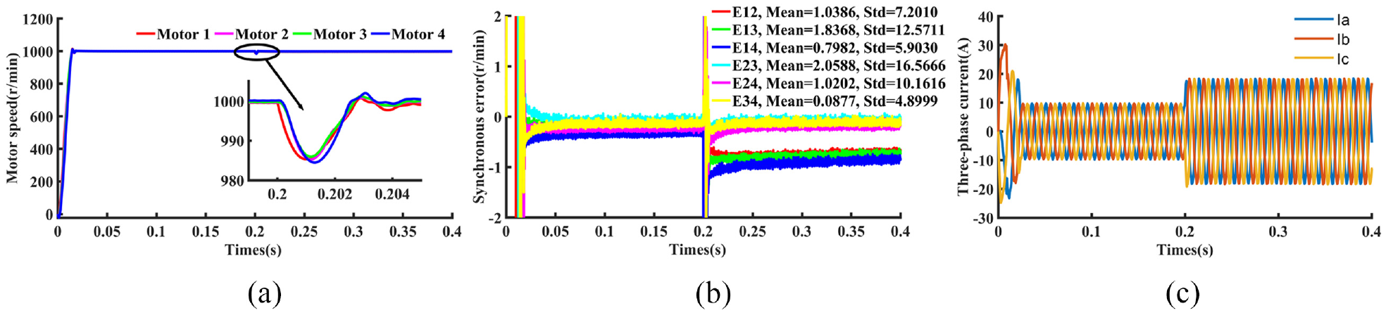
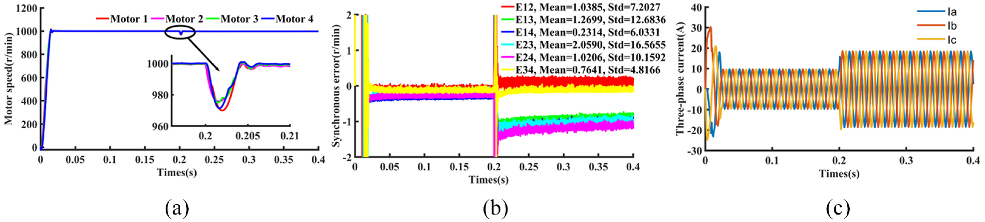
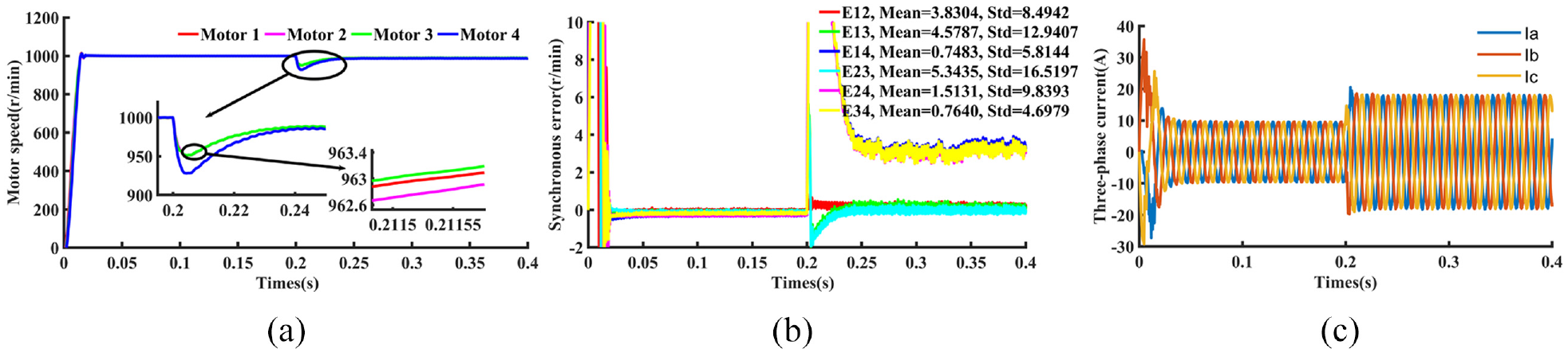
RCC-ABC and PID controller used in case 1: (a) motor speed, (b) synchronous error curve, and (c) variation of three-phase current of motor 1.
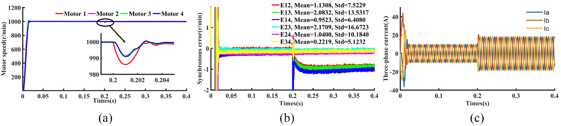
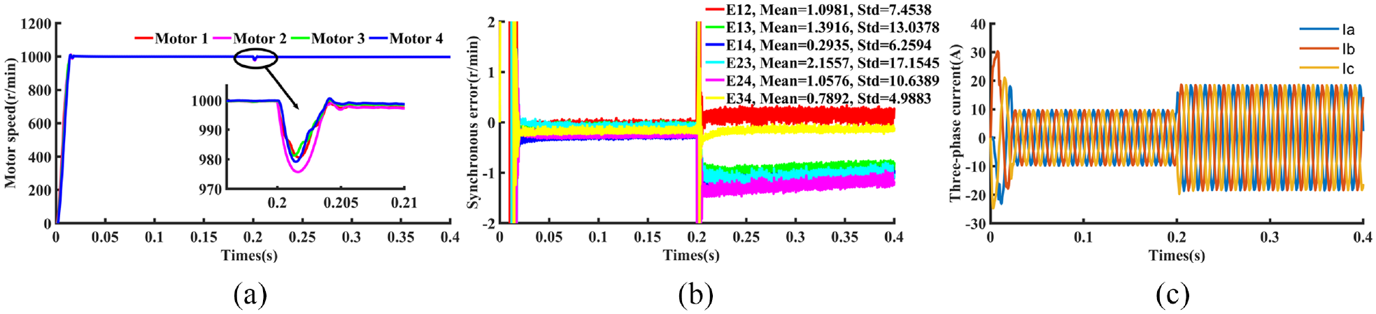
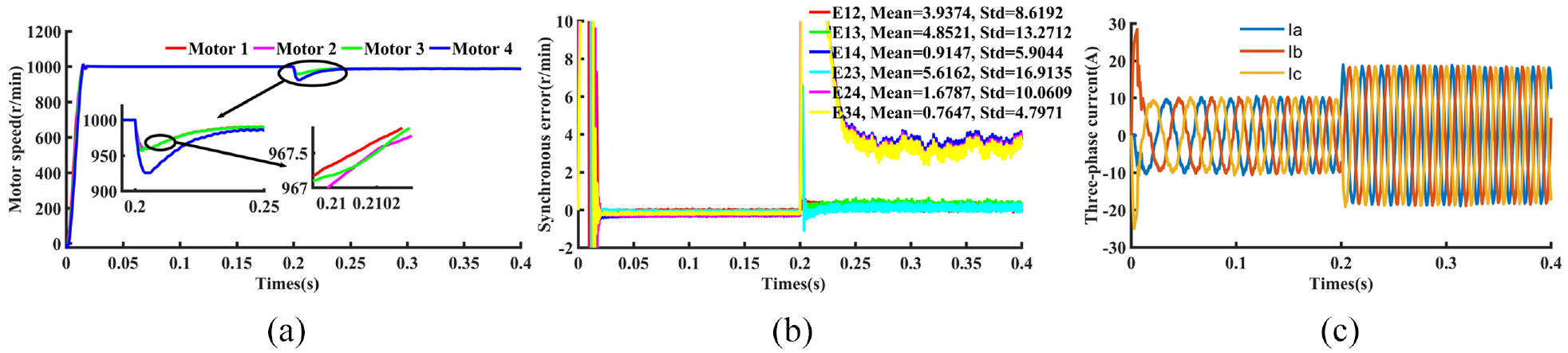
RCC and PID controller used in case 1: (a) motor speed, (b) synchronous error curve, and (c) variation of three-phase current of motor 1.
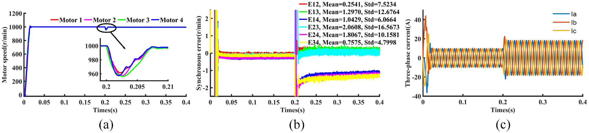
RCC-ABC and PID controller used in case 2: (a) motor speed, (b) synchronous error curve, and (c) variation of three-phase current of motor 1.
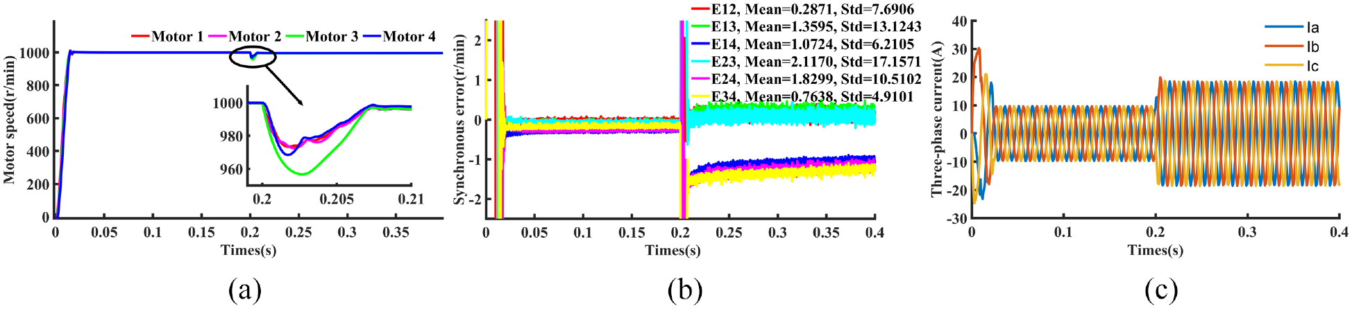
From Figures 6–13, it can be observed with the same two advantages as in Figures 4 and 5: response of four motors is closer to each other and the synchronous error has a smaller Mean and Std. It is also observed that the synchronous error E ij becomes larger due to the sudden increase of load torque TLi. As the number of motors with sudden changes in load torque TLi increases, the trend of increasing synchronous error E ij is obvious. The motor with the greatest variation in load torque has the worst synchronization. The load torque of motor 1 changed from 9 to 18 in Case 1. Motor 1 has the worst synchronization with RCC. But our RCC-ABC keeps the four motors in good synchronization. The same is true for Case 2, Case 3, and Case 4. In any case, however, the RCC-ABC remains well synchronized.
RCC and PID controller used in case 2: (a) motor speed, (b) synchronous error curve, and (c) variation of three-phase current of motor 1.
RCC-ABC and PID controller used in case 3: (a) motor speed, (b) synchronous error curve, and (c) variation of three-phase current of motor 1.
RCC and PID controller used in case 3: (a) motor speed, (b) synchronous error curve, and (c) variation of three-phase current of motor 1.
RCC-ABC and PID controller used in case 4: (a) motor speed, (b) synchronous error curve, and (c) variation of three-phase current of motor 1.
RCC and PID controller used in case 4: (a) motor speed, (b) synchronous error curve, and (c) variation of three-phase current of motor 1.
In summary, the RCC-ABC can keep the speed of each motor in the multi-motor system uniform regardless of the load torque variation, compared with the RCC.
Tracking simulation
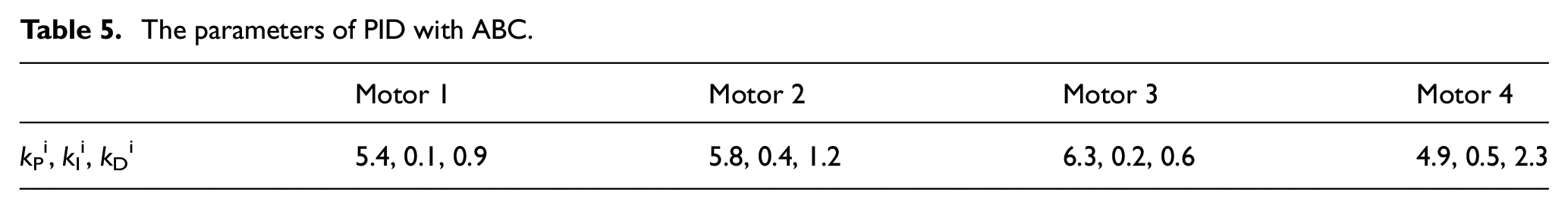
Let the maximum value of reference speed Nref be 200, 400, 600, and 800 r/min, respectively. The input types of reference speed Nref were sine, square wave, and triangle wave. The load torques TLi of the four motors were set to 9, 11, 13, and 15 N/m, respectively. Simulation time t = 40s. The sampling frequency of sine, square wave, and triangle wave was is set to 0.001 Hz. In RCC-ABC, in addition to the PID controller optimized with the ABC algorithm (PID with ABC), two other tracking controllers, SMC 12 and PID controllers 11 were used as a comparison. The parameters kp, ki, and kd of PID for four motors remain 5.6, 0.3, and 1.1, respectively. The parameters kp, ki, and kd of PID with ABC four motors are shown in Table 5. Due to space limitations, only the simulation results of motor 1 are listed in Figures 14–25.
The parameters of PID with ABC.
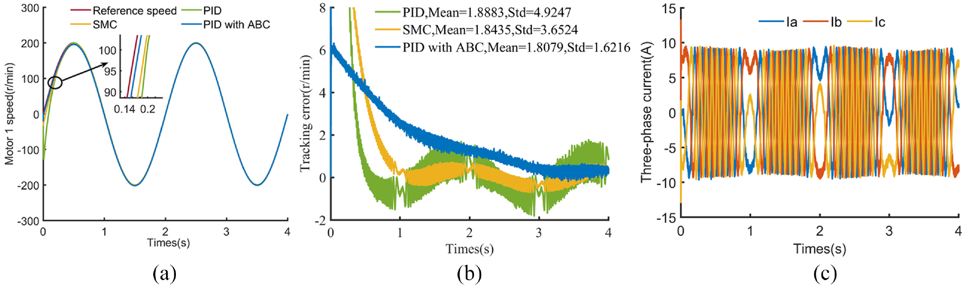
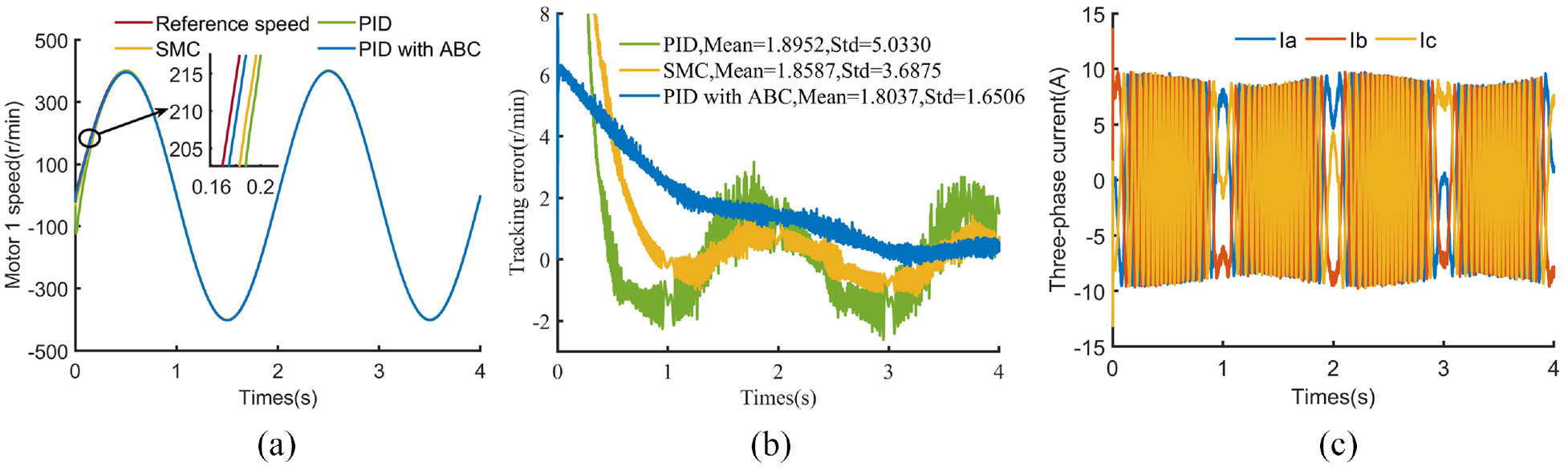
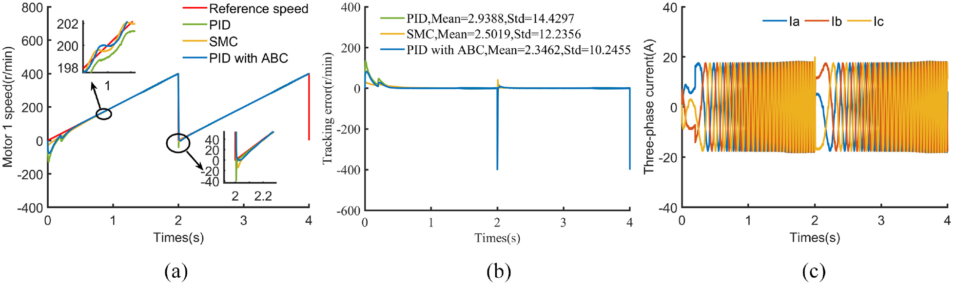
Comparison of tracking controllers for sine input at a maximum speed of 200 r/min: (a) response of motor 1, (b) tracking error curve of motor 1, and (c) variation of three-phase current of motor 1 for PID with ABC.
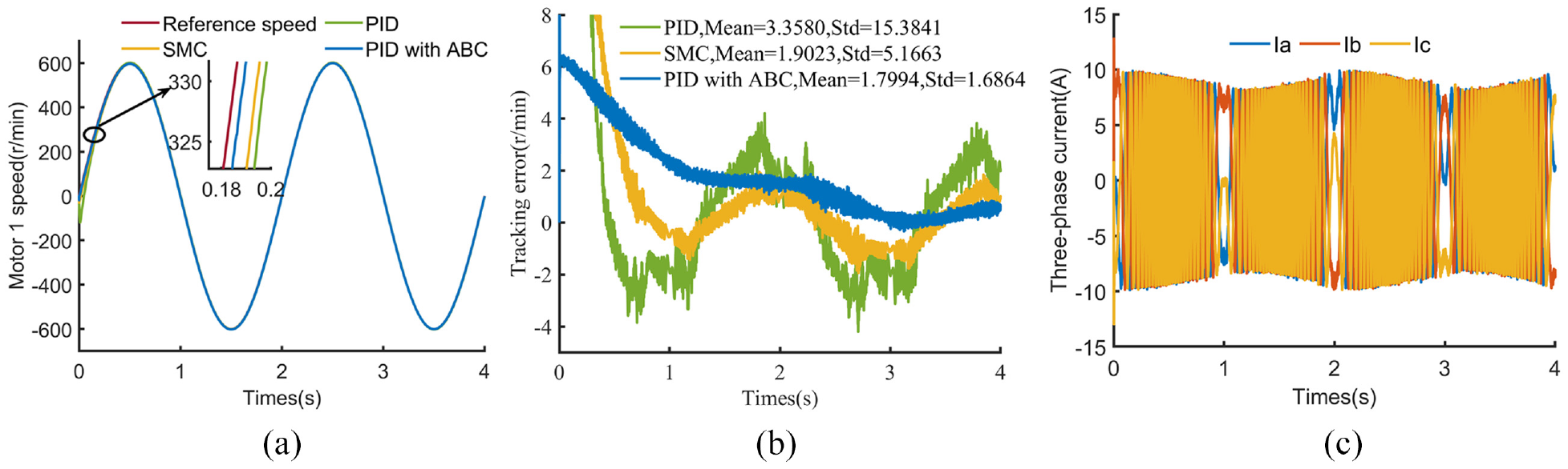
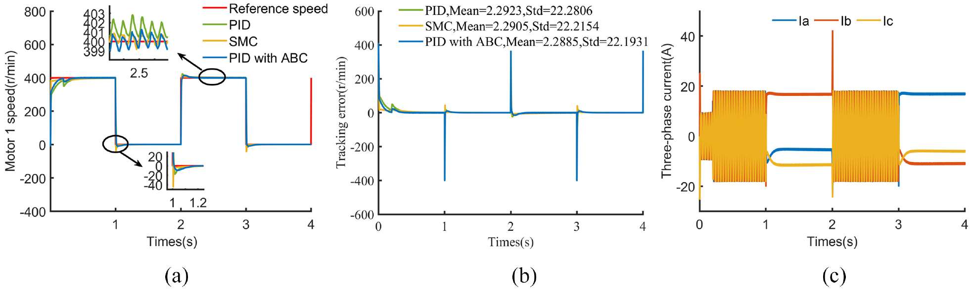
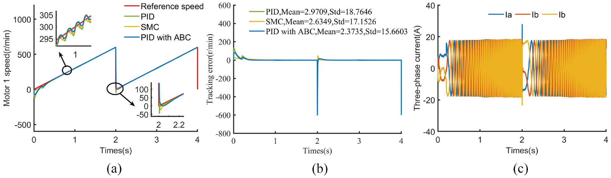
Comparison of tracking controllers for sine inputs at a maximum speed of 400 r/min: (a) response of motor 1, (b) tracking error curve of motor 1, and (c) variation of three-phase current of motor 1 for PID with ABC.
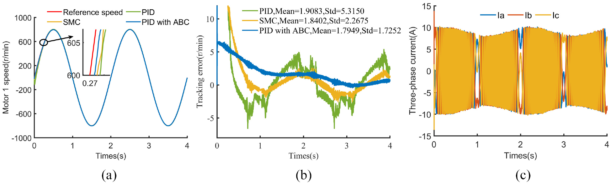
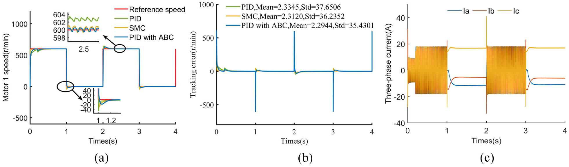
Comparison of tracking controllers for sine input at a maximum speed of 600 r/min: (a) response of motor 1, (b) tracking error curve of motor 1, and (c) variation of three-phase current of motor 1 for PID with ABC.
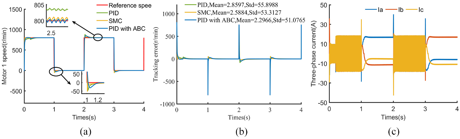
Comparison of tracking controllers for sine input at a maximum speed of 800 r/min: (a) response of motor 1, (b) tracking error curve of motor 1, and (c) variation of three-phase current of motor 1 for PID with ABC.
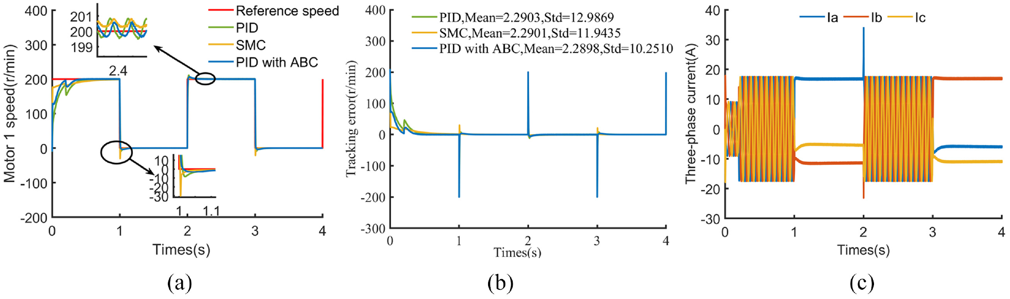
Comparison of tracking controllers for square wave input at a maximum speed of 200 r/min: (a) response of motor 1, (b) tracking error curve of motor 1, and (c) variation of three-phase current of motor 1 for PID with ABC.
Comparison of tracking controllers for square wave input at a maximum speed of 400 r/min: (a) response of motor 1, (b) tracking error curve of motor 1, and (c) variation of three-phase current of motor 1 for PID with ABC.
Comparison of tracking controllers for square wave input at a maximum speed of 600 r/min: (a) response of motor 1, (b) tracking error curve of motor 1, and (c) variation of three-phase current of motor 1 for PID with ABC.
Comparison of tracking controllers for square wave input at a maximum speed of 800 r/min: (a) response of motor 1, (b) tracking error curve of motor 1, and (c) variation of three-phase current of motor 1 for PID with ABC.
Comparison of tracking controllers for triangle wave input at a maximum speed of 200 r/min: (a) response of motor 1, (b) tracking error curve of motor 1, and (c) variation of three-phase current of motor 1 for PID with ABC.
Comparison of tracking controllers for triangle wave input at a maximum speed of 400 r/min: (a) response of motor 1, (b) tracking error curve of motor 1, and (c) variation of three-phase current of motor 1 for PID with ABC.
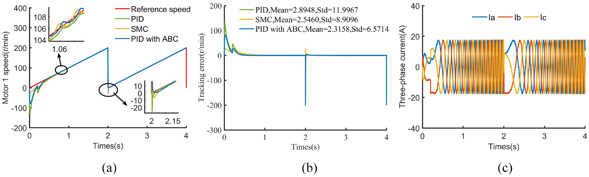
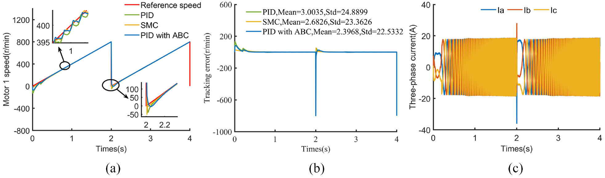
Comparison of tracking controllers for triangle wave input at a maximum speed of 600 r/min: (a) response of motor 1, (b) tracking error curve of motor 1, and (c) variation of three-phase current of motor 1 for PID with ABC.
Comparison of tracking controllers for triangle wave input at a maximum speed of 800 r/min: (a) response of motor 1, (b) tracking error curve of motor 1, and (c) variation of three-phase current of motor 1 for PID with ABC.
In Figures 14–17, the speed profile obtained by PID with ABC is closer to the reference speed profile than SMC and PID. The tracking error obtained by the PID with ABC changes more slowly and is always in a decreasing trend, and finally converges to 0. In contrast to PID with ABC, the tracking error obtained by SMC and PID has large fluctuations that persist until the end of the simulation time. Another noteworthy point is that Mean and Std of the tracking errors obtained by PID with ABC are the smallest for sine input. So the above results verify that the tracking performance of PID with ABC is superior to SMC and PID under sine input.
Next are the simulation results for square wave input and triangle wave input. A common feature can be seen in Figures 18–25: sharp changes in speed lead to a large tracking error that rises with the increase of the maximum value of reference speed. However, this feature is not present in sine input due to its smoother variation (Figures 14–17).The response of motor 1 obtained by PID with ABC is nearer to the reference speed than SMC and PID during the speed smoothing (enlarged plots in Figures 18–21) and speed rising phases (enlarged plots in Figures 22–25). While in the rapid speed change phase (enlarged plots in Figures 18–25), PID with ABC has a small overshoot and quickly transitions to the smoothing and rising phases. In addition, Mean and Std of the tracking error obtained by PID with ABC are also smallest than the other two trackers. The above illustrates that the tracking effect of PID with ABC is better than SMC and PID under square and triangular wave inputs.
In summary, RCC-ABC has good tracking performance under different types of reference speed inputs.
Conclusions
The main goal of the current study was to advance the RCC structure for multi-motor speed synchronization control by incorporating the ABC algorithm. The findings indicate that the RCC-ABC structure was preferable to the RCC structure given the synchronization performance and tracking performance. These findings shed new light on optimization methods applying to multi-motor speed synchronization control. Some limitations to our study should be noted, including that we have only verified the RCC-ABC structure from simulation experiments, and the settings in the simulation experiments are idealized. Future work will investigate that the effect of other advanced optimization algorithms, such as particle swarm optimization (PSO), differential evolution (DE), genetic algorithms (GA), etc., or variant ABC algorithms on the enhancement of the RCC structure.
Footnotes
Declaration of conflicting interests
The author(s) declared no potential conflicts of interest with respect to the research, authorship, and/or publication of this article.
Funding
The author(s) disclosed receipt of the following financial support for the research, authorship, and/or publication of this article: This study was fully supported by Liaoning Provincial Department of Education Basic Research Projects for Higher Education Institutions, China (LJKZ0301); The Scientific Research Foundation of the Education Department of Liaoning Province, China (2017LNQN22); Young Teachers Foundation of University of Science and Technology Liaoning, China (2017QN04).