
Abstract
The optical measurement technology could reduce manual work and improve quality in assembly. The confocal scanning scheme is proposed to measure the narrow gap in-line but it is hard to identify the edges of a gap. This paper proposed an edge definition and presented an edge identification method for gap measurement. The edge profile is defined as a part of a circle, which could be identified by the shutter time feature. The defined edge point could be calculated by fitting the edge profile, and then the width of a gap section is calculated by two edge points. The width of a gap can be evaluated by the average of several gap section. The experimental results indicate that the repeatability of the method is less than 2 µm and the precision of the measurement is higher than ±2.5 µm. The proposed method is feasible for in-line measurement application in assembly.
Introduction
The background
The assembly gap is usually applied to indicate the assembly quality in some assembly task such as the car body assembly, 1 tip clearance in turbine, 2 clearance of Gyro motor, 3 etc. These gaps are measured for adjustment or record by manual gauge 4 in past. To reduce the manual work and improve assembly quality, the optical measurement methods are applied for automation measurement such as vision measurement 5 and line laser scanning. 6 The inductive sensor is also applied for the gap measurement7,8 but it is improper for in-line measurement.
The measurement result of the vision measurement and line laser scanning is difficult to satisfy the measurement requirement as the gap is narrow (<100 µm). The image calibration and edge identification limit the precision of the vision measurement; the related works9,10 show that improving precision needs plentiful data and complex intelligent algorithm. However, the data is often lack or limit in some cases. The line laser scanners have been applied in the in-line measurement of the car body assembly, which the line laser scanner could measure the width of a gap in X direction and the height of the surface in Z direction. The resolution of the line laser scanner in X direction is much lower than Z direction, which is unable to obtain high-precision measurement results.
Higher precision measurement method is required in some engineer cases. The external gap of the container used in underwater vehicle 11 should be controlled as it affects the streamline. This external gap ranges arrange 10–100 µm and should be measured to evaluate whether the shell is assembled tightly. To satisfy this requirement, the measurement range should cover 10–100 µm and the precision should be higher than 5 µm.
The proposed measurement method for the gap
A confocal scanning based method is proposed to measure the narrow gap in line. The in-line measurement scheme for a gap is illustrated in Figure 1, which consists of a high precision movement mechanism, a confocal chromatic displacement sensor 12 and the fixture. The high precision movement mechanism is applied for counting the length between edges of the gap. The confocal chromatic displacement sensor is mounted on a movement mechanism to identify the edges of the gap.
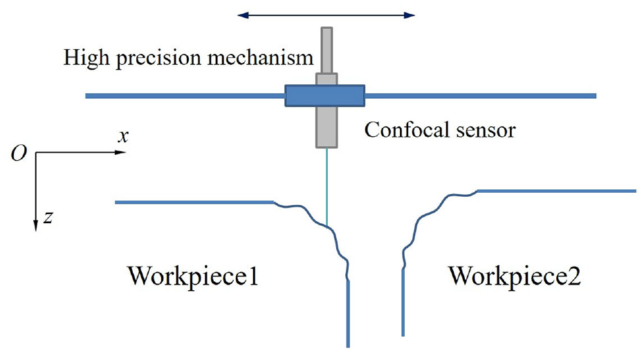
A gap measurement scheme based on the confocal scanning.
The gap measurement steps are:
Fixture of the movement mechanism is firstly mounted near to the workpieces so that the measured surface is in the measuring range of the sensor, and the gap is in the movement range of the mechanism.
Mechanism is moved through the gap and the sensor records displacement.
The measurement data of the sensor is evaluated for identifying the edges of the gap.
The movement velocity and time between the edges of the mechanism are applied to calculate the width of the gap.
The crucial step of this method is the identification of the gap edges. There are many factors (e.g. form error of the surface, measurement angle of the sensor, etc.), which could make the edge vague. With the effect of these factors, some data arrange edge could be unreliable. So the measured data cannot be applied immediately. This paper proposes an identification method of the edge to solve this problem.
The related works of the edge identification
The edge of a workpiece is obtuse and vague in microscope. 13 The research of the Groeger et al. 14 shows that the real edge is a zone and the nominal edge is a line in the zone (see in Figure 2 14 ), which the shape of the real edge zone is important to the gap measurement.
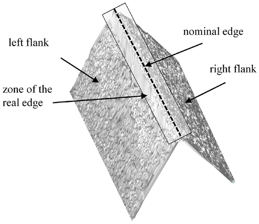
The cutting edge features.
Some works focus on the shape of cutting edge, since the shape could affect the efficiency of cutting.15,16 Some works of the cutter indicate the edge of a workpiece could be approximately treated as a part of circle or ellipse in a section, for example, Lv et al. 17 explored the effects of cutting edge radius on cutting force, tool wear and life in milling. It is called fillet assumption in this paper and some contributions have been made based on this assumption. Vopát et al. 18 used the cutting edge radius to indicate the performance of plasma discharges in electrolyte. Bernard et al. 19 applied the edge radius to study the thermo-mechanical effect on cutting, which shows the larger edge radius could increase the roughness. Arefin et al. 20 established a contact relationship between the tool edge and the workpiece, which the cutting performance of vibration-assisted machining is evaluated based on the relationship. Luo et al. 21 developed a novel mechanistic model for carbon fibre-reinforced plastics/Ti-6Al-4V stacks based on the character of cutting edge radius. Li et al. 22 adopts the cutting edge radius and the workpiece material to investigate the size effect in micro end milling. Yang et al. 23 formulated an analytical modelling of residual stress in orthogonal cutting by tool edge radius effect. These contributions show that the assumption is reliable and we could also apply it for the edge identification.
The shape of an edge could be measured by optical method or even microscope, which is evaluated by the edge radius. 24 Zhang et al. 25 proposed a measurement method for high-precision cutting edge radius of diamond tools by atomic force microscope. Song et al. 26 proposed a new method for hard whirling tool edge reconstructing based on fractal interpolation, in which the edge radius is measured and reconstructed in a section. Zhao 27 formulated a modelling and detection method for cutting edge radius, which could predict the radius precisely. Wu et al. 28 established an in-situ measurement system to measure the waviness of rounded cutting edge of diamond tool, which shows the edge could be measured in-line. The works of the edge measurement indicate that it is possible to measure a part of the edge zone by the optical measurement method such as the confocal scanning. The measurement precision of the optical method is limited by the measuring angle, unfortunately, the measuring angle is increasing when the measure points approaches the real edge. In other words, the precision of the measuring results near the real edge is lower than the measuring results remote to the real edge.
To promote the precision of a gap by the optical method, this paper applied the fillet assumption to predict the profile near real edge based on the measuring points in edge zone, which the measuring angle of the measuring point is small. An edge definition is proposed and a gap evaluation method is also provided based on this definition.
The edge identification method and the gap evaluation method
The assumption and the definition for the edge identification
The definition of the edge is theoretical foundation of the edge identification. Firstly, two assumptions are applied to assure the accuracy and robust of the edge identification method.
The actual form of the edge is important for the identification of the edge. The actual form of the edge can be approximate to a fillet in most of the cases. In other words, the section profile of an edge (as detailed in Figure 3) could be regarded as a part of circle.
The effect of geometrical error: (a) orientation error and (b) form error.
The geometrical error in the assumption includes orientation error and form error. The orientation error means the angle of the out flank and gap flank, and the form error means the variation of the flank and edge surfaces. As illustrated in Figure 3, if the orientation error is large, then the gap could be narrow near the measured surfaces but wide inside. The geometrical error could make the width of the gap variation inside, in this case, the width of gap inside is hard to evaluation by the measurement method. The form error could affect the section profile of the real edge, if it is large enough, the form edge could be uncertain and difficult to identify.
According to these assumptions, the edge zone can be regarded as a small fillet and we could use a circle to fit the measured data of the section profile of an edge. And the edge zone and the nominal edge could be defined by definition 1 and 2, which is illustrated in Figure 4.
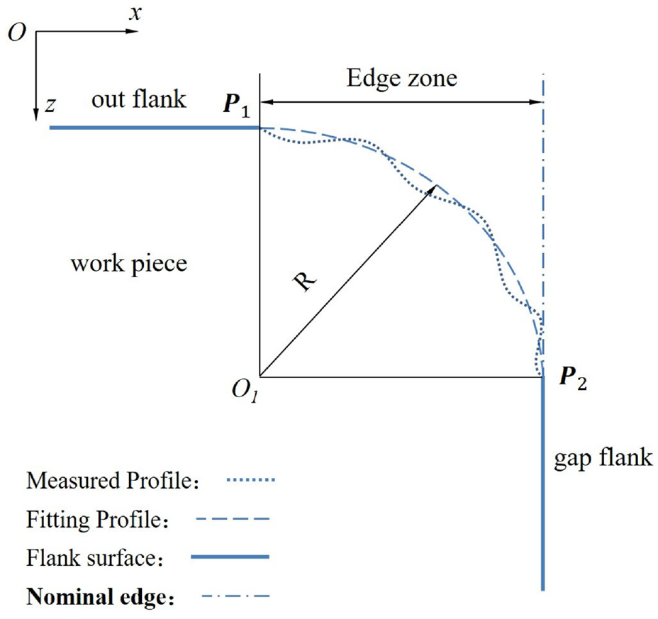
The definition of edge zone and nominal edge.
When the edge in a section is evaluated, the edge zone is a line profile, the nominal edge is a straight line and the
The identification of the edge
The gap measuring method could only capture a section of the edge zone in one measurement and the problem of the edge identification is to find the
To solve that, we proposed to fit the edge profile by a circle and calculated the position of
Then the crucial problem is how to find the profile for fitting. The cross point
Four groups of data can be record in one measurement that is displacement, shutter time, optical intensity and peak. The sensor controls optical intensity in a small range by adjusting shutter time to keep the measurement result (displacement) reliable. The shutter time has upper limit which determined by the sampling frequency. When the measuring angle increases, the shutter time increases to keep the optical intensity. If the measuring angle is too large, the shutter time reaches upper limit and the optical intensity cannot keep in the range.
This principle could be applied to find out a point set of the edge profile, and the method to find the point set is detailed as:
When the shutter time of a measuring point is twice larger than the average value, the measuring point is regarded as a point of edge profile, which the point is marked as x1.
When the shutter time of a measuring point reaches upper limit, the measuring point is considered as an unreliable point that would not be used for fitting edge profile, which the point is marked as x2.
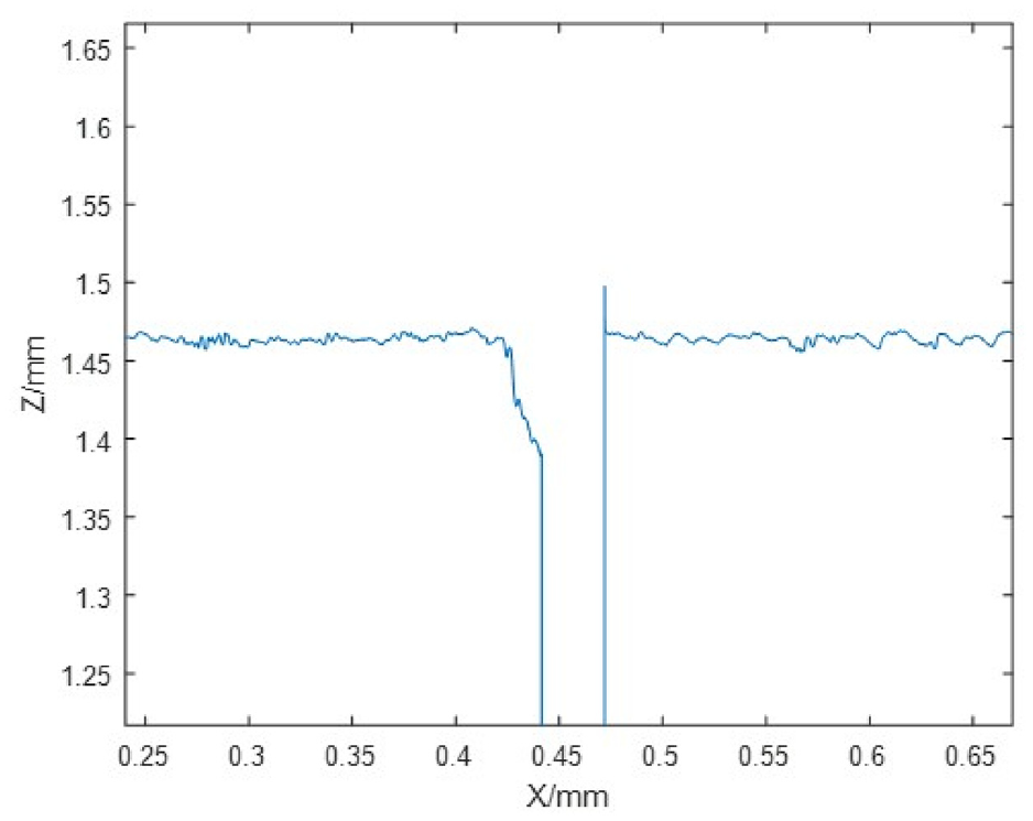
The measuring points between x1 and x2 are a point set of edge profile (detailed in Figure 5), and then the fitting profile could be fitted by this point set.
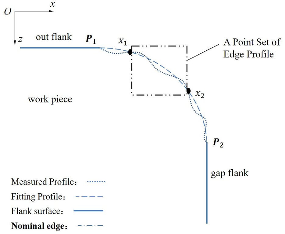
A point set of edge profile.
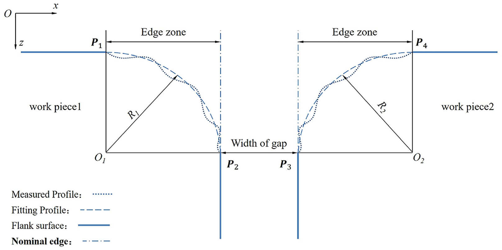
The point set is fitted to a circle by least square method. The position of the circle centre and the radius of the circle are obtained, which are marked as O1(xo, zo) and R1. The position of the edge point
The edge point of each measured section could be identified by the method above.
Gap evaluation method
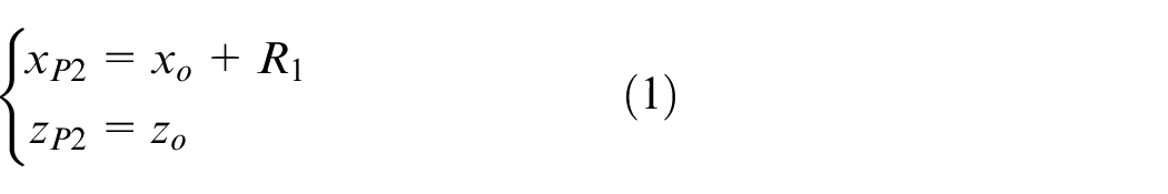
Based on the definition of the nominal edge, the width of a gap is the length between
A gap should be measured several times in different sections. In a section, the
The width of a gap in a section.
The position of the
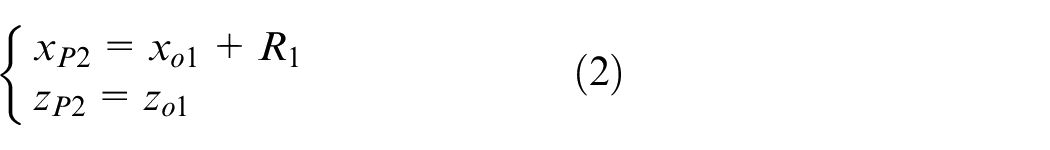

where (
Then the width of a gap in a section is calculated as:

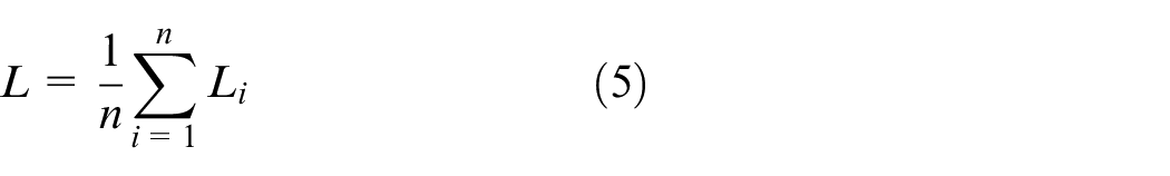
And the width of the gap is:
Experiment and discussion
Experimental setup
The measurement system employed in the verification experiment is shown in Figure 7. The high-precision mechanism and the support of the confocal sensor are fixed on the table, which the movement direction of the mechanism is defined as X direction. The confocal sensor is fastened on the support, which the direction of the sensor is defined as Z direction. A standard gap sample is mounted on the mechanism. The out flank of the sample is in the measurement range of the sensor, which the out flank is perpendicular to the Z direction.
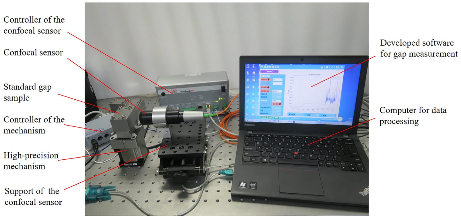
The experimental setup for verification.
The resolution, repeatability and the range of the apparatus is enough to verify the edge identification method and the gap evaluation method. The measuring range of the confocal sensor is from 20 to 23 mm in Z direction, the measuring resolution in Z direction is less than 50 nm and the sampling frequency range from 1 to 6000 Hz. The bidirectional repeatability of the mechanism is ±0.5 µm, the moving range is 13 mm in X direction and the velocity can be control in 0.001–5 mm/s, which means that the measurement system could measure the gap less than 12 mm. The precision and the stable ability of the mechanism are important, which determines the upper limit of the measuring precision of the method.
The developed software is applied to control the high-precision mechanism and confocal sensor synchronously. The velocity of mechanism, sampling frequency and movement range can be set by the software. The gap evaluation method is also integrated in the software so that the measurement results of a gap could be obtained.
Several standard gap samples are manufactured to verify the proposed the definitions and methods, which is should in Figure 8.
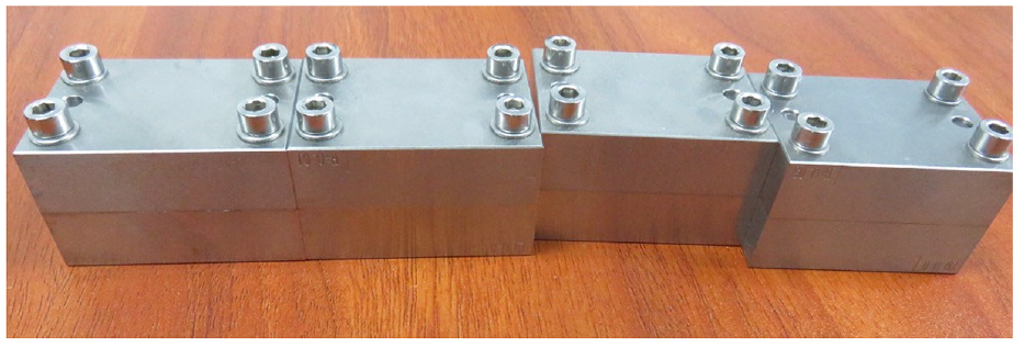
The standard gap samples for verification.
The standard gap sample is manufactured precisely and its accuracy is controlled in ±1 µm. Three samples are applied for verification and their nominal width values of the steps are 30, 50 and 70 µm. The proposed measurement method is applied to evaluate these gaps and the results are compared to the nominal values.
Experimental results
Some experiments are carried out for verification. Firstly, three points of each sample are measured three times. Then measurement result of each time is recorded. The measured width of the gaps and the variations are calculated to evaluate the repeatability. The measurement time results of a sample are recorded and listed in Table 1. The measured width in Table 1 is the average of the three measured results. The variation is the difference of the maximum result and minimum result.
The measurement results of a sample.
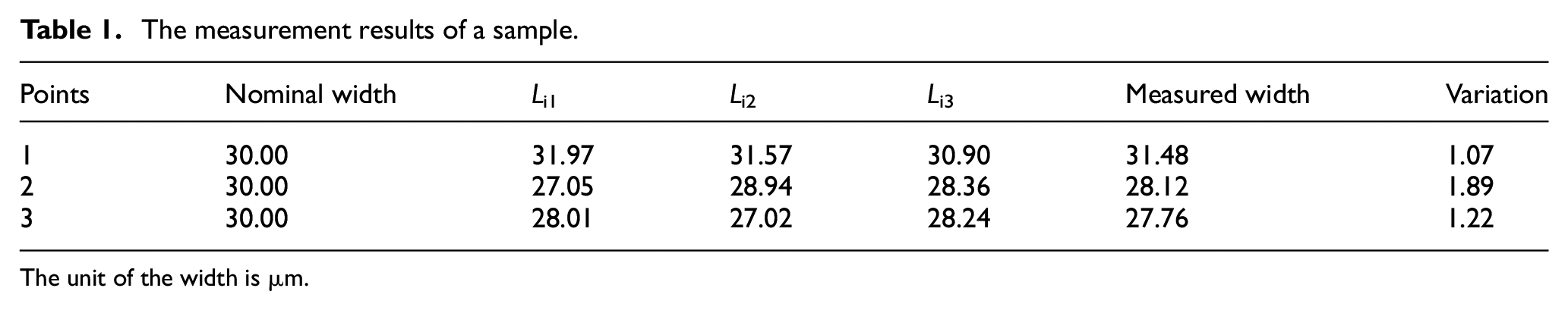
The unit of the width is µm.
As shown in Table 1, the measured width of the gap is 29.12 µm by calculating the average of the measured data.
The measured result of each point of three samples are recorded and listed in Table 2 and the variations are calculated to evaluate the robust.
The measurement results of three samples.
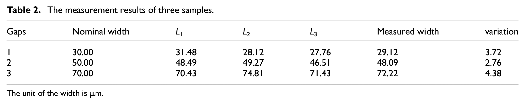
The unit of the width is µm.
The measurement data is processed to draw the profile and the edge profile for analysis. The fitting profile of a measured edge is plot in Figure 9, which includes the measurement points of the profile, fitted profile, circle centre and the evaluation of the edge point. The actual edge profile used for identification is a part of a circle profile according to the Figure 9.
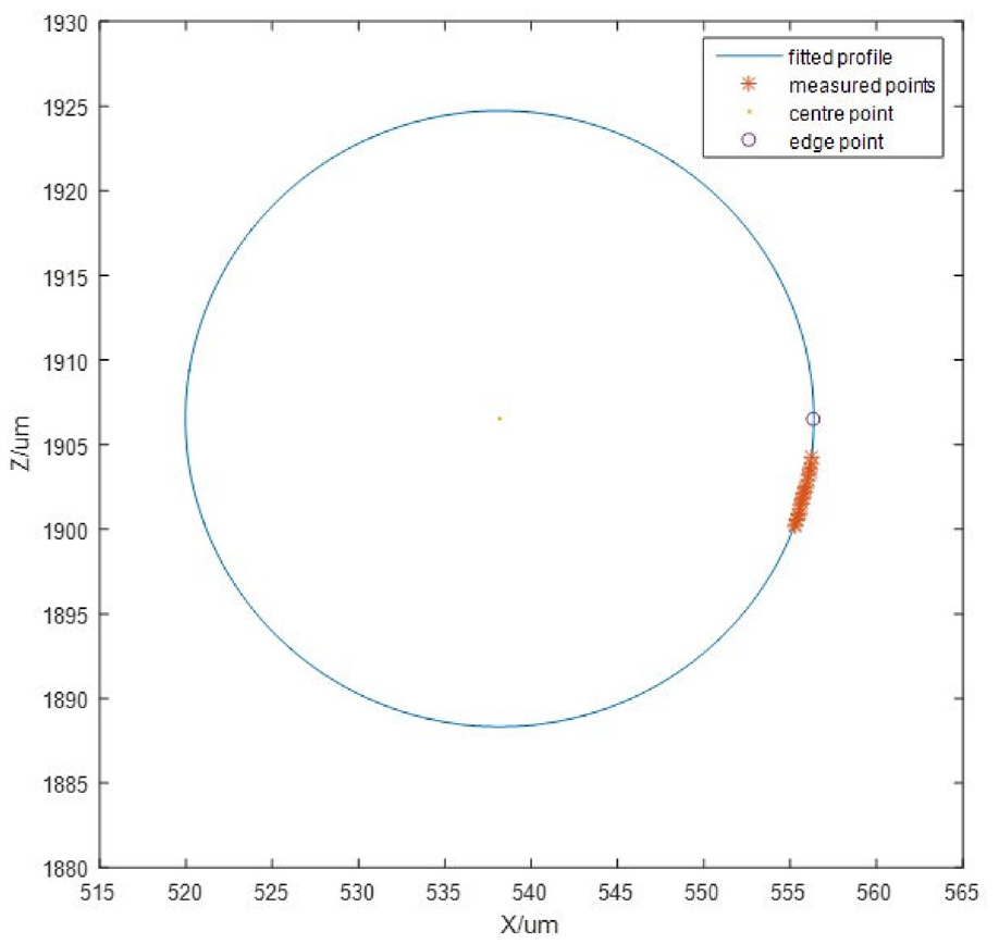
The fitting profile of a measured edge.
The experimental results analysis
The measurement repeatability
To exclude the effect of the installation of the sample, several measurement results of a measured point are compared. The repeatability of the measurement is less than 2 µm according to Table 1, which is about 1 µm higher than the bidirectional repeatability of the mechanism.
The measurement robust
The robust is evaluated with the consideration of the installation, orientation error, form error, etc. The parallel error between the workpiece and displacement machine could affect the precision little as the gap is narrow and the measuring edge is calculated by the measuring profile in edge zone. To consider the geometrical error, the variation in Table 2 shows that the measurement is robust as the variation could be controlled in 5 µm. The variations in Table 2 are much larger than the variation in Table 1, which the difference is about 2–3 µm.
The estimation of edge identification and gap width evaluation
The Figure 9 shows that the fitting of the edge is accord with the definition proposed in Section 2.1, when the assumption is admissible, which means that the edge identification method is feasible. The precision of the gap width could be calculated compared to the nominal value in Table 2, which shows that the precision is higher than ±2.5 µm.
The measurement efficiency
The position of the sensor in X direction should be adjusted roughly first before the measurement. Then the travel range of the mechanism could be controlled in 0.5 mm. When the velocity is set as 50 µm/s and measuring times of a point is set as 3, the measuring time of a point is 30 s.
The drawbacks of the evaluation method
The discussion above shows that the repeatability, robust, precision and efficiency are acceptable for in-line measurement application in assembly. However, there are still some drawbacks which limit its application.
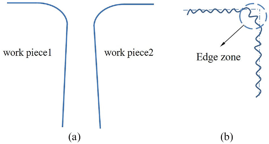
For some reason, the edge profile might be irregular as illustrated in Figure 10. It could not be approximately treated as a fillet. So it is unsuitable for the proposed method to find out the edge point.
The situation of irregular edge profile.
The proposed method could only evaluate the width around outflank but the manual gauge could evaluate the gap width inside. This limitation is also existed in other optical measuring method such as vision measurement.
The geometrical error of a gap could much affect the measurement result as one section of the gap is evaluated in an installation. Multiple sections should be measured to minimise this effect and it could decrease the measuring efficiency and import installation error.
Conclusions
An edge identification method and a gap evaluation method are proposed for a confocal scanning based in-line gap measurement. The edge definition is firstly formulated based on fillet assumption. The shutter time feature is applied to find the edge profile and the edge definition is used to find the edge point. Then the width of a gap in one section is calculated by the position of two edge points. Some experiments for verification are carried out and the results show that: (1) the edge identification method could find out the edge point; (2) the gap evaluation method could be used for in-line measurement of narrow gap.
The experiment results also shows some limitations that should be undertaken in future work: (1) the precision of the method decreases as the edge of a gap is irregular; (2) the geometrical error of the gap could not be evaluated by the method; (3) the experiment is finished by the standard gap samples which has not been verified in engineering cases.
Footnotes
Declaration of conflicting interests
The author(s) declared no potential conflicts of interest with respect to the research, authorship, and/or publication of this article.
Funding
The author(s) disclosed receipt of the following financial support for the research, authorship, and/or publication of this article: Project supported by CAEP Foundation (CX20200012).