
Abstract
The radiating power with sine waveform is required for modulated infrared thermography nondestructive testing. Sine voltage was applied by former authors for deriving sine power waveform. The theory mode of infrared lamp is proposed. According to numerical solution and FFT analysis, high frequency components are included in the radiating power waveform, when sine voltage is set to drive the lamp. A light intensity sensor was utilized for monitoring the real-time radiating power, and a close-loop power tracking system was constructed. Fractional order sliding mode controller was selected in the tracking system, for its robustness and flexibility property. The reachability of the controller is proved and the calculation formulas of reach time are given. In experiment, the tracking results with both PID and sliding mode controller were derived. Lower tracking overshoot and better robustness was derived through the sliding mode controller, compared with the PID counterpart.
Introduction
Infrared thermography nondestructive testing (NDT) has been rapidly developing in recent years. Its research and application are of great significance to improve the safety and reliability of aerospace vehicles, military equipment, and civilian industrial equipment. 1 Infrared thermography NDT is an active approach, where an external stimulus is applied to the specimen in order to induce relevant thermal contract between regions of interest. 2 The exciting source could be divided into two types: optic and non-optic. 3 The method discussed in this article could be applied to most optic exciting sources.
For specimen with low thermal conductivity, such as carbon fiber reinforced plastic (CFRP), the test piece needs to be fully heated for defect detection. The stimulation energy required is high and the heating time takes minutes.4,5 Modulated infrared thermography (MT) which is also referred as lock-in thermography is appropriate method. 6 In MT, the heating power is modulated to a sine waveform. Then sine component is included in surface temperature information which is recorded by thermal camera. For defect and non-defect area, the transmission and reflection time of thermal wave is different. According to the phase difference of surface temperature between defect and non-defect area, sub-surface defect of specimen is detected.
The combination of function generator and power amplifier is generally utilized for driving the heating lamp.7–11 This is based on the assumption that a sine heating power waveform is generated, when the lamp is driven by a sine voltage. It is true when cycle of driving voltage is seconds or less. Because of thermal inertia, the temperature change of filament couldn’t follow the transient power change in one cycle. The resistance of filament keeps relatively stable within one voltage cycle. When the voltage period increases to a few minutes, the filament temperature changes dynamically over a voltage cycle. The assumption is not applicable any more. High frequency components are included in the radiating power waveform. For MT, the detection sensitivity depends on the modulation frequency, even blind frequency was shown for defect at a special depth and thickness.5,12 The detection effectiveness is weakened when the phase information of different frequency points is mixed together. To solve this problem, an infrared light intensity sensor was used to monitor the heating power and close-loop power tracking system was constructed. In order to deal with disturbance of environmental light change, slide mode controller (SMC) was applied for the real-time power tracking.
In recent years, SMC is widely researched and applied in science and engineering fields because of its strong robustness.13–15 The radiating power tracking system is prone to be disturbed by lighting system and changes in external ambient light. The strong anti-interference characteristic of SMC is preferred for the tracking system under discussion. Fractional order (FO) SMC has been applied in various engineering system, such as electromechanical transducers, 16 antilock braking system, 17 permanent synchronous motor, 18 and wind turbines. 19 Chakrabarty and Bandyopadhyay 20 investigated the generalized switching law for discrete time SMC. In our previous work, 21 fractional order sign function was introduced in switching law of SMC. Better performance was disclosed comparing with integer order counterpart. The SMC with fractional order sign function is also utilized in this radiating power tracking system.
Theory mode of the controlled object – heating lamp is proposed. Relation among driving voltage, filament temperature of heating lamp and radiating power is given by differential equation. Numerical solution was applied for evaluation of the radiating power waveform when the lamp was driven by sine voltage. Further FFT analysis disclosed harmonic distortion of the radiating power waveform, especially in the case of dual frequencies sine voltage. The analysis declares why close-loop tracking system is necessary for getting sine radiating power waveform. The sliding surface and equivalent control law is derived according to the theory mode. Filament temperature is chosen as state variable. The tracking performance is challenging because the state variable is defined in fourth-order state equation. The reachability of controller is proved with Lyapunov method and the calculation formulas of reaching time are given. An experiment platform was constructed for close-loop radiating power tracking. Some tricks of the platform such as sampling data preprocessing and communication between custom software and Simulink are introduced. PID controller is usually the first choice in engineering application because of its simplicity and mature theoretical basis. The platform was tested with both SMC involved and PID controller. Lower tracking undershoot at initial phase and better robustness for environmental light change was derived with SMC, while better tracking accuracy was with PID controller.
Problem statement
Sine voltage V in (1) was applied for driving the heating lamp.7–11 It was inferred that the radiating power with sine waveform was derived, which is necessary for modulated infrared thermography NDT.

where E is the amplitude and
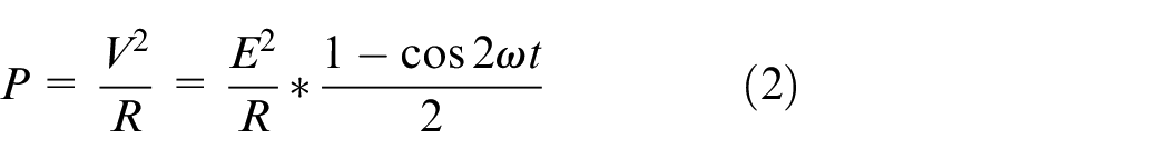
The electric power P is sine wave at twice frequency of the driving voltage, in combination with a DC component. It was thought to be equal to the power radiated to specimen.
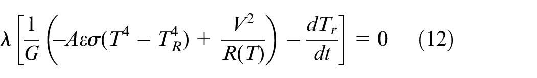
Actually mass of heating lamp filament is small and its heat capacity is pretty low. When the period of sine wave is minutes, the temperature of filament would be changing dramatically along with different transient voltage of the sine wave cycle. Equation (2) is no longer applicable.
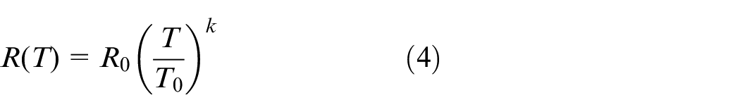
The commonly used heating lamps are kinds of incandescent lamp. The radiating power

where A is the radiating surface area.
where
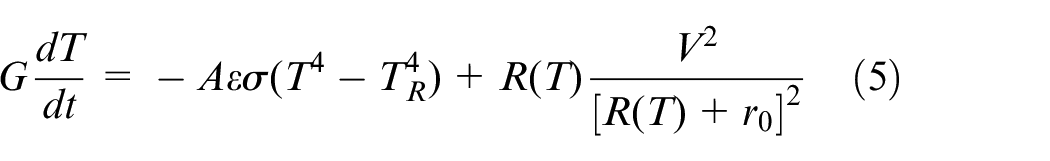
where G is heat capacity of filament. G is calculated to be
The differential equation (6) could be numerically solved by MATLAB ode45 function. Sine voltage in (1) with amplitude E = 220V and angular frequency
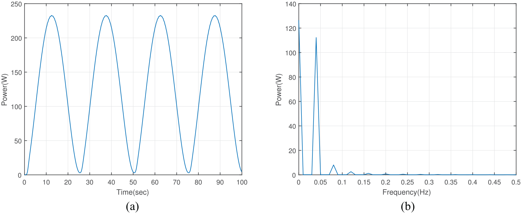
Waveforms produced by sine voltage: (a) radiating power and (b) power spectrum.
FFT analysis was applied for the radiating power and the spectral distribution is shown in Figure 1(b). In addition to DC and fundamental component 0.04 Hz, high frequency harmonics is shown at 0.08 Hz and above. The total harmonic distortion (THD) is 7.7%.
In recent years, a new detection method - amplitude modulated thermography (AMT) was proposed. 9 In AMT, voltage including multi frequency components was applied for driving the lamp. It was expected to get radiating power components at double of these frequencies. For example, the voltage includes two frequency components 0.01 and 0.02 Hz, as shown in (7).

The corresponding radiating power was also evaluated by numerical solution of (3)−(6), as shown in Figure 2(a). The spectral distribution was calculated by FFT, as shown in Figure 2(b).
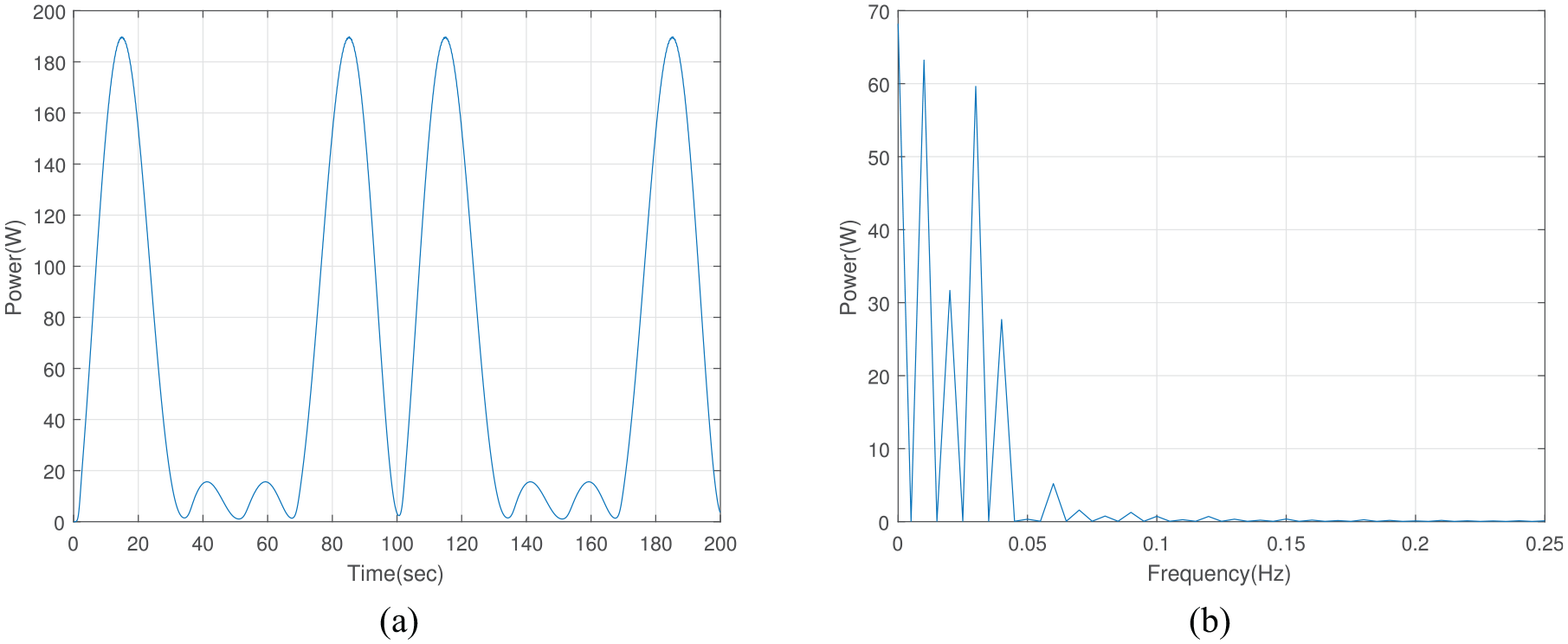
Waveforms produced by synthetic voltage: (a) radiating power and (b) power spectrum.
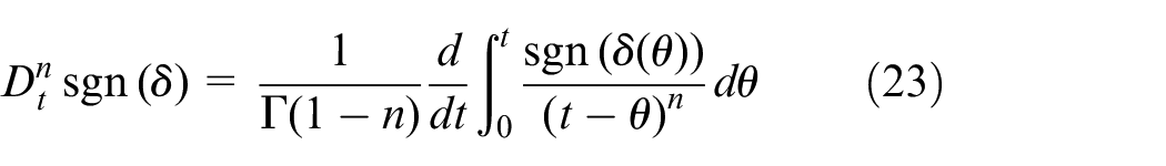
With the synthetic voltage input, the radiating power at expected double frequency 0.02 and 0.04 Hz is even lower than the intermediate frequency 0.01 and 0.03 Hz. The result is far from expectation.
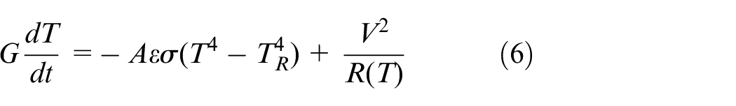
According to theory mode described in (3)–(5), the radiating power
Sliding mode controller design
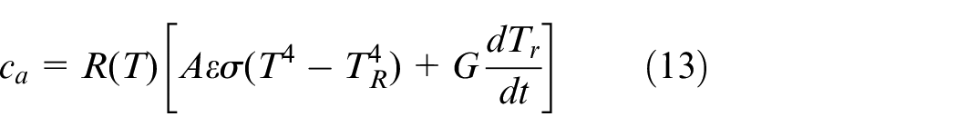
The tracking system of radiating power is prone to be disturbed by environmental light change. Robustness is required for the tracking system. The SMC with fractional order switching function is constructed for radiating power tracking. The temperature of filament T is selected as state variable. In the experiment, the feedback captured by sensor Si1133-AA00 is light intensity

where S is the area of the irradiated region. In the real case, the radiating power is generally not evenly distributed. However, if the relative assembly location of the lamp and sensor is changeless, the light intensity captured by sensor is proportional to the total radiating power. There is a fixed relation between the state variable T and the feedback variable
Sliding surface and control scheme design
The sliding surface is selected as

where
Base on the mode of state variable in (6), one can get
Let the control law
where the equivalent control law
Let the exponential rate switching law be

where
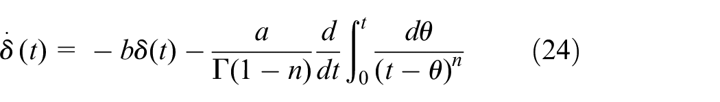
Stability and reachability analysis

Based on (10) and (12), one gets
Bring the controller
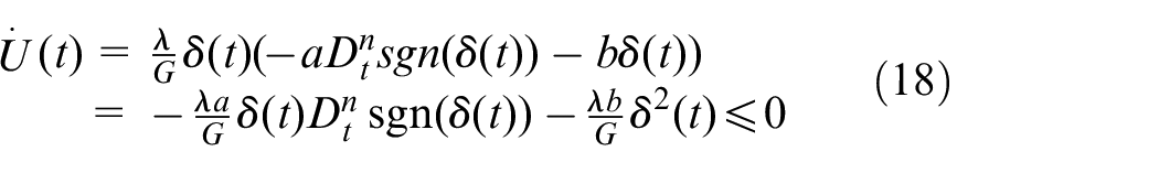
Therefore, the controlled system could reach the switching surface in finite time. The proof is completed.
Next, the computation formulas of reaching time will be discussed.
Before discussing the reaching time
1) When the initial condition

Because of
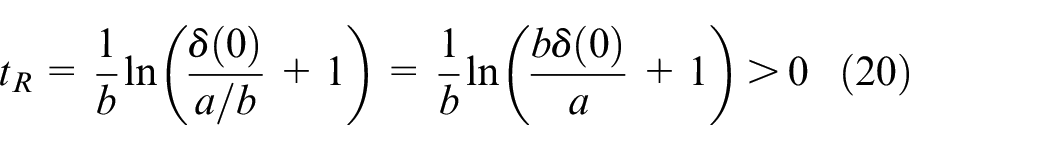
2) When
According to the analysis of cases 1) and 2), it could be concluded that
Similarly,
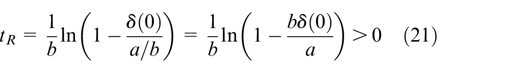
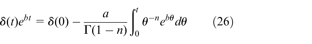
3) When
Then, one gets
Furthermore, one gets

Therefore, one has
While
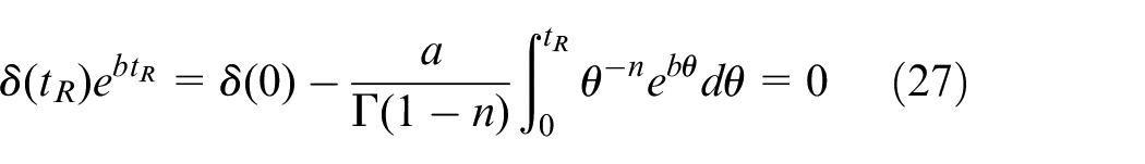
Thus, the solution of (27) is
Therefore, numerical approximation could be used to obtain
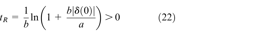
4) When
Similar to 3), one can get
Furthermore, one has
Let
So, the arriving time
From the analysis in cases 3) and 4), it could be concluded that
The stability and reachability analysis ensures the convergence of the radiating power tracking system and provides theory basis for parameter adjustment in SMC.
Experiment verification
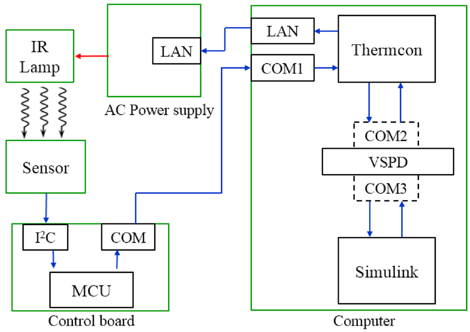
A close-loop system was constructed for radiating power tracking, as shown in Figure 3.
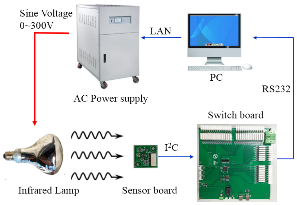
Close loop system for radiating power tracking.
The SMC is executed on PC and the controlled object is the infrared lamp. The lamp is powered by a programmable AC power supply. The output of power supply is amplitude modulated voltage waveform. The amplitude (0–300 V) and frequency (45–500 Hz) of carrier signal is programmable. In the experiment, the frequency was fixed at 100 Hz and the amplitude depended on the modulated signal which was decided by controller output. The light intensity of the lamp is monitored by a light sensor SoC (System on Chip) Si1133-AA00. Both visible and infrared photodiodes are integrated in the sensor. The output of infrared photodiode is selected as control feedback. In addition, the photo current to voltage conversion circuit, analog-digital converter, signal processor and a micro controller are also integrated in the single
The sampling rate of light sensor is configurable. It was set to be 1 kS/s in the experiment. The sensor output reflected not only the modulated signal, but also the fluctuation caused by 50 Hz lighting system and 100 Hz carrier signal. A moving average filter in duration of 20 ms inside chip was configured for eliminating these fluctuations. The captured light intensity information is sent to the switch board through Inter-Integrated Circuit (I2C) interface. When the switch board received the light intensity sampling value, it sent the value to PC through cluster communication (COM) port immediately. The experiment setup is shown in Figure 4.
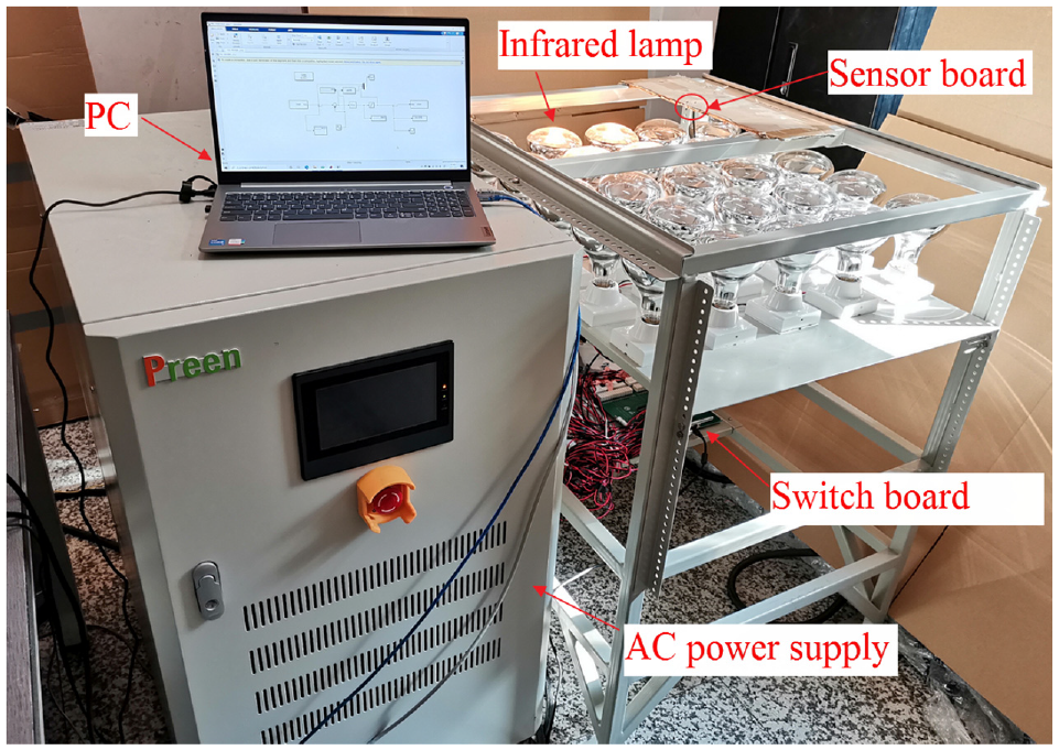
Experiment setup.
The radiating power of a single infrared lamp is generally not quick enough for heating the CFRP specimen. A
A software “Thermcon” operated on PC was designed for communication with switch board and power supply. The output of SMC is a series of unsigned 16 bit integer value. 65,535 represents the 300 V maximum output voltage of power supply. It is converted to amplitude value of modulation signal by Thermcon and sent to power supply through standard commands for programmable instruments (SCPI). The switching command of lamp matrix and sampling feedback is transmitted and received through COM1 port, which is possessed by Thermcon. A graphic interface was designed for lamp matrix switching operation. As a demonstration in Figure 5, the five lamps at position of white dots are switched on, while others are switched off. The detail of control signal loop is shown in Figure 6.
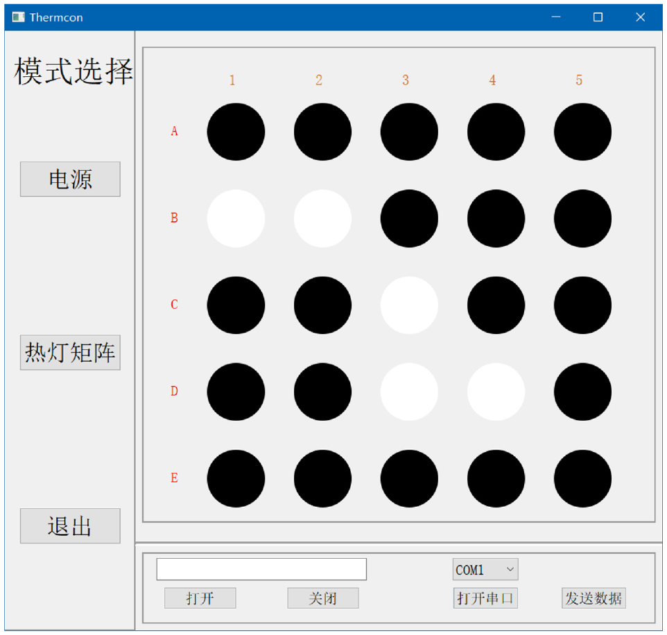
User interface of Thermcon.
Control signal loop.
The switching command of lamp matrix needs to be specified only once after power on. It is not part of the control loop, so it is not shown in Figure 6. The light intensity feedback and power supply amplitude control information is interchanged between Thermcon and Simulink through a pair of virtual COM ports. There is no easy way for real-time data exchange between a self-designed software and Simulink. A third-party software virtual serial port driver (VSPD) is utilized for creating two interchangeable virtual COM ports: COM2 and COM3. They are possessed by Thermcon and Simulink respectively.
Both PID controller and SMC were used for radiating power tracking. For speeding up the defect detection of CFRP, higher effective power is preferred. The reference signal was set to be a sine waveform with high DC offset, as shown in (34).

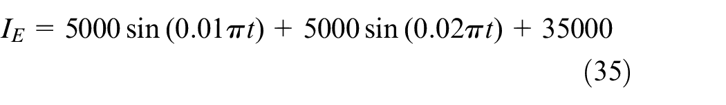
Furthermore, the reference signal was set to be dual sine components with DC offset as shown in (35).
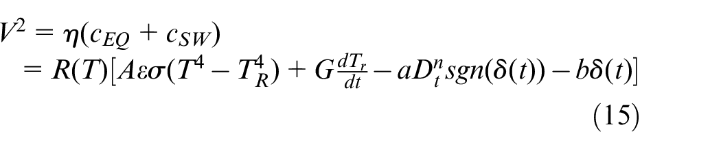
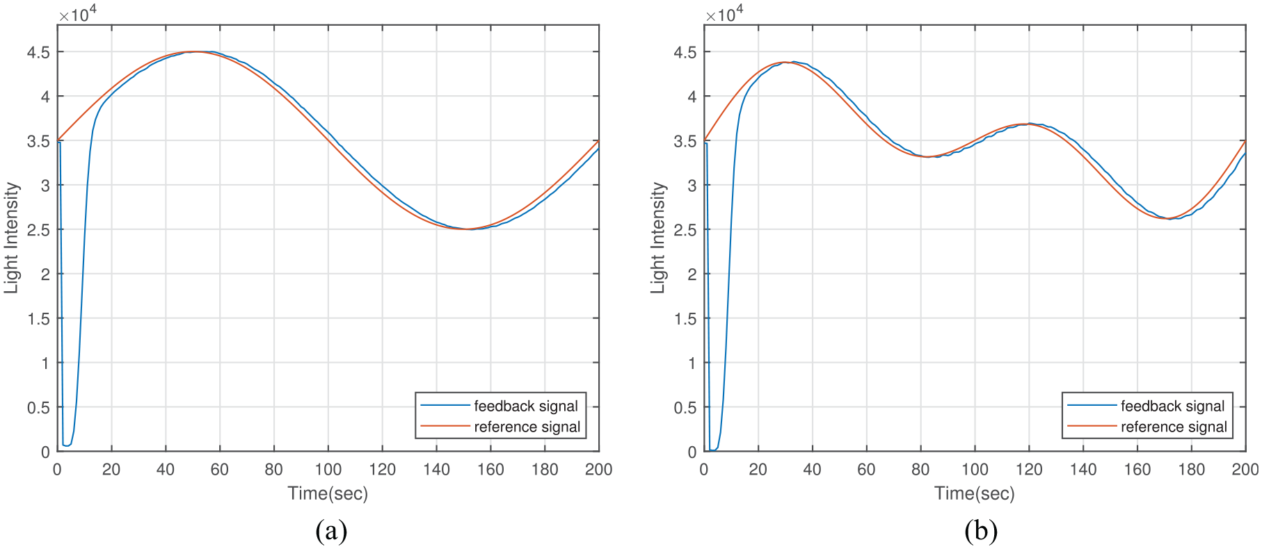
The test results of PID controller with sine and dual sine reference signal are shown in Figure 7(a) and (b) respectively. The test results of SMC are in Figure 8(a) and (b). For both waveform of SMC, the parameters in (15) were set to be:
Test results of PID controller with: (a) sine reference signal and (b) dual sine reference signal.
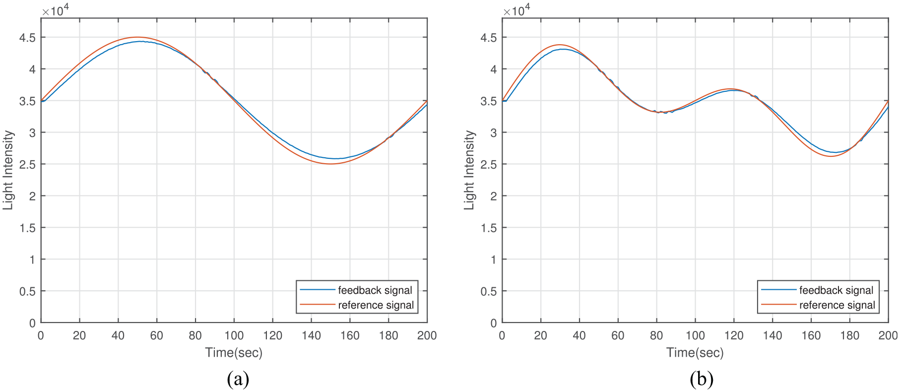
Test results of SMC with: (a) sine reference signal and (b) dual sine reference signal.
The primary drawback of the PID test result is undershoot at the initial phase. The equivalent control law of SMC involves theory mode of lamp. The initial error between reference signal and feedback could be compensated. Tracking lag is shown in both test results of PID controller and SMC. The tracking ripple of SMC is comparable to PID counterpart, but the tracking accuracy is worse. Reference signals in (34) with same offset but various amplitude were tracked by SMC. The result is shown in Figure 9.
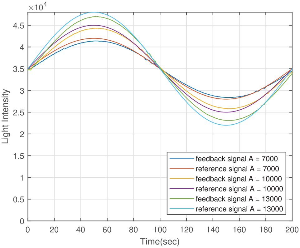
Test result of SMC at various amplitudes.
The reference signals with different amplitude could be tracked, but all are with tracking errors. The higher tracking error is derived with higher amplitude. The error is caused by defective control law in (13), which is based on theory mode defined in (3)−(6). The emissivity
To verify robustness of the controller, a flash light was used for simulating the transient ambient light change. The flash light was used to illuminate the light sensor in tracking status for about 1 s and removed immediately. Both the illumination time and space between sensor and flash light were controlled by hand, so the repeatability of overshoot is not so good. The experiment was done for both PID controller and SMC The test result of PID controller is shown in Figure 10(a), while SMC is in Figure 10(b).
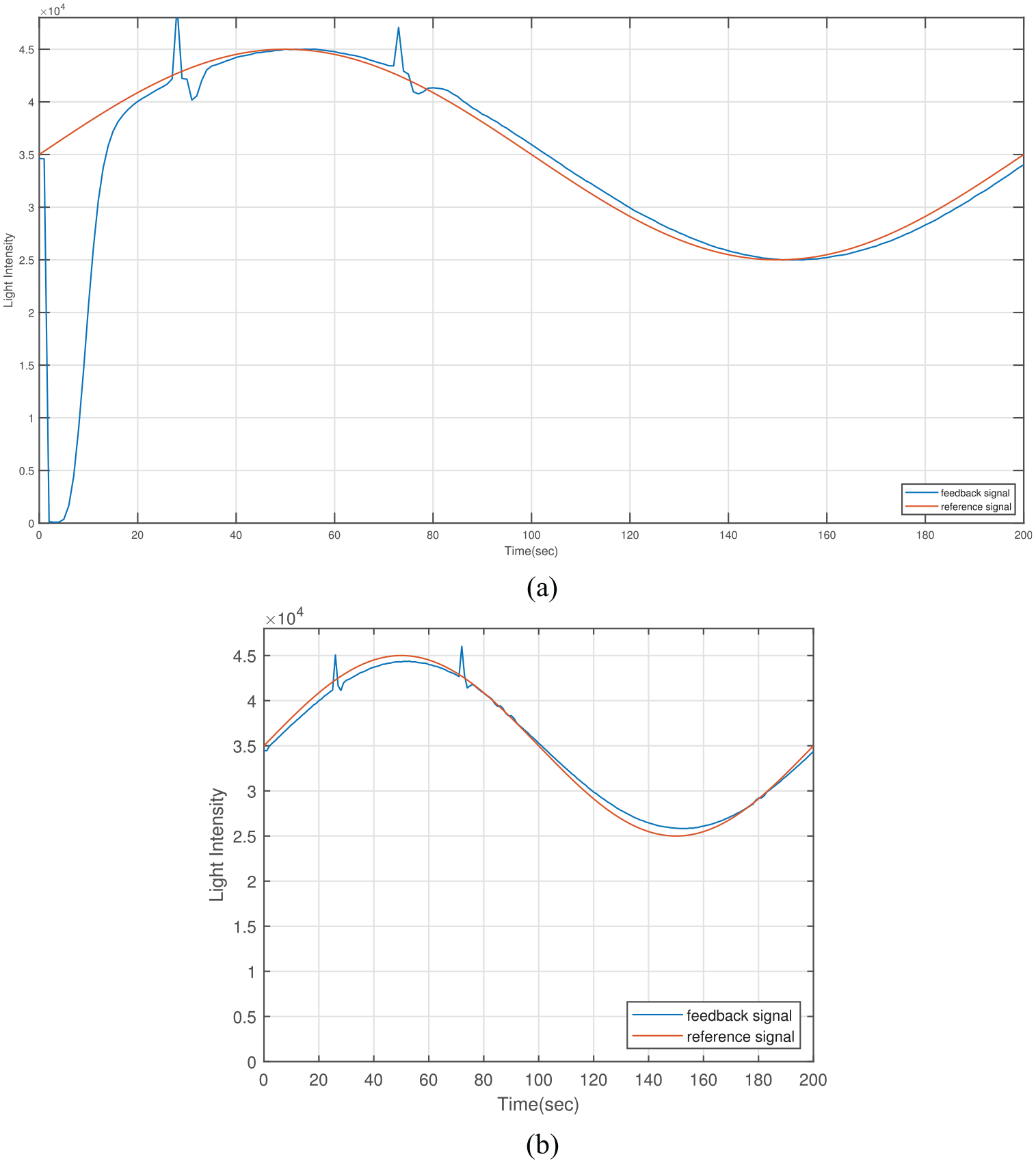
Robustness test result of: (a) PID controller and (b) SMC.
The two overshoots at time points of 27 and 73 seconds are caused by illumination of flash light. The sensor feedback value is sum of infrared lamp and flash light illumination at these moments. The tracking waveform of SMC returns to original trajectory in 2 s following the overshoot, while PID controller returns in 7 s. The undershoot amplitude of SMC is much smaller than PID counterpart. Advantages of SMC in robustness is shown by this experiment. The radiating power tracking system with SMC is more prone to be immune from ambient light interference.
Conclusion
Numerical solution and FFT analysis of the IR lamp theory mode disclosed why sine radiating power could not be derived with sine driving voltage. An experimental platform was constructed for radiating power tracking of IR lamp. Design details of the platform were proposed. Fractional order SMC was constructed in Simulink for close-loop tracking. The filament temperature T defined in fourth-order state equation was selected as state variable. The Lyapunov method was used for proving the reachability of the system. The analytic expressions of reaching time
The SMC showed better dynamic performance, comparing with PID controller, but tracking accuracy was worse. Improvement of the theory mode is necessary in the further study. The minimum programing interval of the current AC power supply is 1 s. It decides the control interval of whole system. Power supply with lower programing interval (<50 ms) would be utilized in the future. The performance of controller is expected to be further improved. Defect detection effectiveness with the tracked radiating power will be evaluated.
Footnotes
Declaration of conflicting interests
The author(s) declared no potential conflicts of interest with respect to the research, authorship, and/or publication of this article.
Funding
The author(s) disclosed receipt of the following financial support for the research, authorship, and/or publication of this article: This work was supported by Sichuan Science and Technology Plan Project 2019ZDZX0038