
Abstract
Due to unpredictable factors, the model predictive direct power control (MPDPC) exists weak robustness when the parameters change of three-phase rectifying converter. Therefore, this paper introduced Fractional Active Disturbance Rejection Control (FADRC) into the MPDPC system to improve the robustness of rectifying converter, that is, the power loop of PID controller in conventional model predictive control is replaced by FADRC. In order to verify the effectiveness of the proposed control strategy in this paper, a model of three-phase rectifying converter is established in MATLAB, and the simulation is conducted. Compared with the control effects of the MPDPC with PID (MPDPC-PID) control strategy and MPDPC with Linear Active Disturbance Rejection Control (MPDPC-LADRC) under different operational scenarios, the simulation results demonstrate that the MPDPC with FADRC (MPDPC- FADRC) strategy has best disturbance rejection capability, robustness and rapidity, and it can significantly reduce the voltage fluctuation of DC bus. This study can provide a valuable guidance and reference for the design of the efficient and stable three-phase rectifying converter.
Introduction
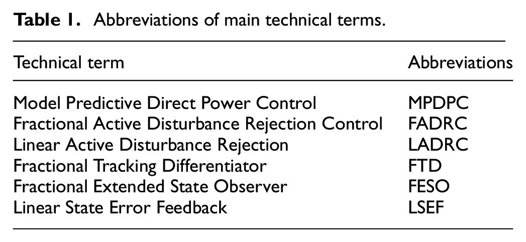
Three phase rectifier is widely used in Industrial production and manufacturing. The performance of rectifier is closely related to its control. The control strategy of rectifying converter mainly includes current closed-loop control strategy based on PI adjustment,1,2 Proportional-Resonant (PR) control strategy, 3 deadbeat control strategy, 4 hysteresis control strategy, 5 etc. Each control method can achieve the effective control of the rectifying converter, but they all exist respectively deficiency. The mentioned control strategy mainly depends on the parameters of PI adjustment, and design of the PI parameters generally is quite complicated. 6 The parameters of PR control strategy are difficult to adjust. 7 The deadbeat control strategy is highly depending on the system parameters, and the selection of parameters largely determines the accuracy of the deadbeat control strategy. Hysteresis control strategy need high sampling frequency and high-order harmonics. 8 In recent years, various high quality control strategies have been proposed by experts and scholars, among which the model predictive direct power control strategy is simple and easy to be implemented. Main Abbreviations in this paper is summarized in Table 1.
Abbreviations of main technical terms.
However, MPDPC strategy also has disadvantages such as large switching frequency and large current distortion. 9 In order to solve the problems of MPDPC strategy, scholars have put forward a large number of corresponding algorithms to improve MPDPC strategy. In Literature,10,11 the model predictive power is built by using the grid current and grid voltage together with its signal of delay, and the difference in capacitor voltage. Afterward, the optimal switching state under MPDPC is selected to effectively eliminate the double-frequency pulsation in the active power output from the rectifier as well as current harmonics, which can realize the accurate tracking of the given active power and reactive power. Literature,12,13 presented a predictive power control based on virtual flux for three-phase rectifier. The mathematical model of predictive power control for rectifying converter is established in coordinate frame. In each sampling cycle, the appropriate voltage vector and the conduction time are selected to control IGBT. In Literature 14 presents an improved MPDPC strategy for three-phase rectifying converter. This strategy applies voltage vector pairs during the control period, then uses the Lyapunov function to select voltage vector pairs which satisfy the closed-loop stability criterion, and applies the voltage vector pairs the next control period. Compared with the conventional MPDPC method, this strategy can reduce the average of switching frequency and losses while reducing the amount of calculation.
However, the effects of external environment changes, uncertainty of system model and internal parameter disturbances on the voltage of DC and its stability have been ignored. The three-phase rectifying converter based on model predictive power control strategy is a typical, nonlinear, multivariable and strong coupling system, 15 which is very sensitive to disturbance and system parameter changes. Therefore, conventional linear control strategies are difficult to achieve ideal control effect.
The LADRC strategy is a simple and robust algorithm, which does not rely on the accurate model of the controlled system. 16 In order to increase the controllability of LADRC and improve the control precision, the literature 17 proposed a FADRC strategy which is combined of ADRC technology with a fractional calculus theory. FADRC strategy not only has the advantages of LADRC strategy, 18 but also increases the degree of freedom of controller parameters, thus the overall performance of the controlled object were improved. 19
Therefore, in this paper, the FADRC is applied to the three-phase rectifying converter control system to further improve the anti-disturbance ability of the DC bus voltage. This paper not just builds the power prediction model of the rectifying converter based on the FADRC but also designs a closed-loop power controller of the rectifying converter based on the FADRC. Finally, the rectifying converter model based on MPDPC is established in MATLAB. The effectiveness and superiority of the control strategy proposed in this paper are verified by the comparison of MPDPC-PID, MPDPC-LADRC, and MPDPC-FADRC.
Voltage vector model of three-phase rectifying converter
The topology structure of the three-phase rectifying converter is depicted in Figure 1.
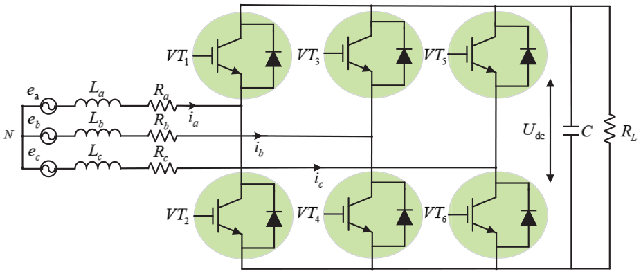
Diagram of three-phase rectifying converter topology structure.
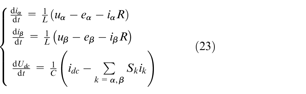
According to Figure 1, the mathematical model of the three-phase rectifying converter in the three-phase static coordinate system is established by Kirchhoff’s Law, 20 it can be written as
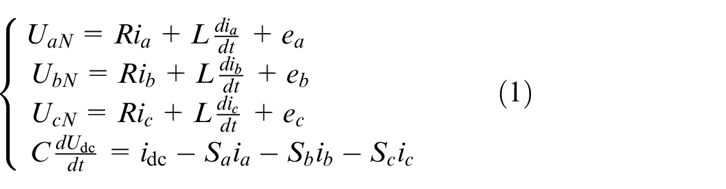
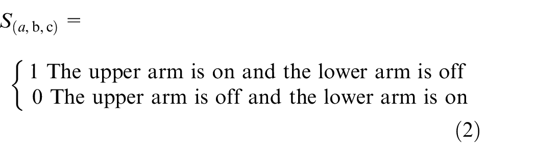
Equation (2) is the switching control state of the rectifying converter,
The switching signal represented by space vector is written as
Thereinto,
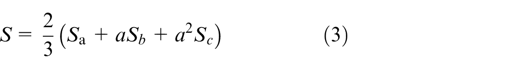
Output voltage vector can be written as
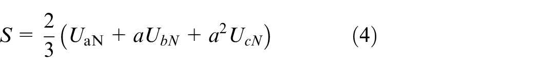
Form equations (3) and (4), the relationship between the output voltage vector

The three-phase rectifying converter topology consists of six switches, so there are eight switching states, namely: 000 100 110 010 011 001 101 111, and the corresponding number of voltage vector is also eight. The vector voltages in different switching states are summarized in Table 2.
Vector voltages in different switching states.
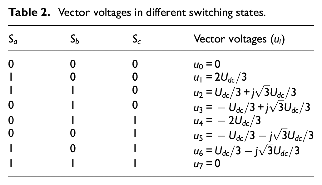
There are seven different states because of
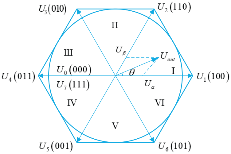
Diagram of converter voltage space vectors.
Principle of the FADRC
The fractional active disturbance rejection controller is composed of Fractional Tracking Differentiator (FTD), Fractional Extended State Observer (FESO), and Linear State Error Feedback (LSEF). 21 Thereinto, FTD can smooth the start process and quickly track the input signal of the system without overshoot, and it can produce an excellent differential signal. FESO is the core of the active disturbance rejection controller, which can mainly estimate the error between the actual control object and the internal nominal control object. LSEF determines the quantity of the error feedback according to the system state error.
Thus, a FTD can be constructed as
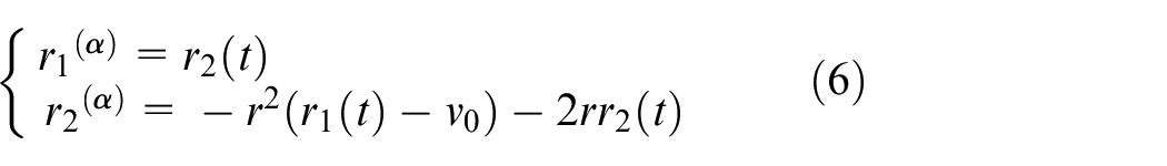
Supposing a fractional system as

where
If the intermediate variables are set to
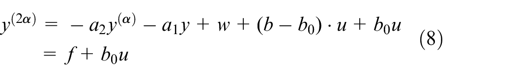
Where
Where equation (10),
The corresponding FESO can be expressed as
Where
Therefore, FESO of the fractional active disturbance rejection controller can be written as
Where
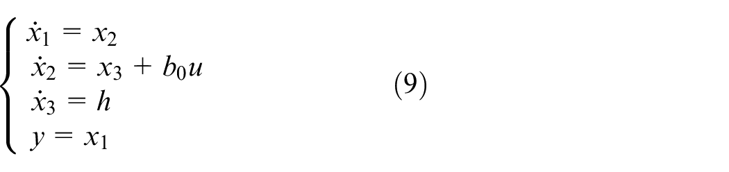
Assuming the control quantity

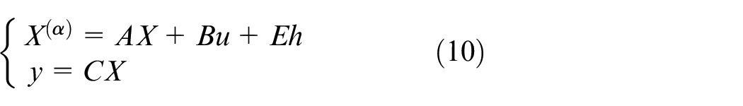
The fractional order system expressed by equation (8) is transformed into a series of fractional integrators

Fractional active disturbance rejection controller can be designed as
Where
For varying disturbances of the system, the response speed of FESO is determined by its bandwidth, so the higher value of
By substituting the observer bandwidth
In order to ensure the observation accuracy of the observer for the total disturbance and realize the real-time compensation for the total disturbance, the bandwidth of the observer
FADRC schematic diagram is depicted in Figure 3.
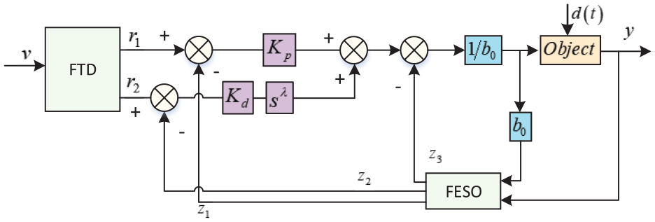
Structure schematic diagram of FADRC.
The transfer function of FADRC is written as
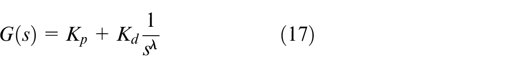
Where
Therefore, the closed-loop transfer function of the controlled object can be expressed as 22
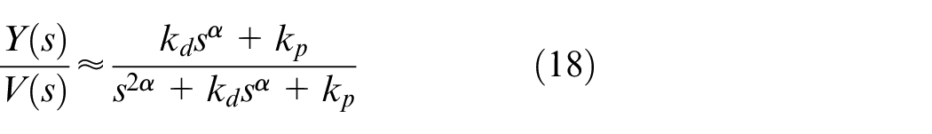
Since the fractional derivative of the step signal setting value is not a pulse signal, the control rate
FADRC predictive power control
Principle of model predictive control
The basic principle of the model predictive direct power control strategy is illustrated in Figure 4.
23
At time
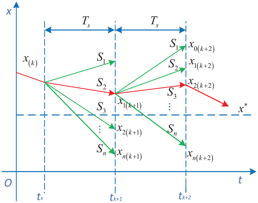
The principle of model predictive control.
MPDPC of three-phase rectifying converter
Principle of instantaneous active power and reactive power in the static coordinate system can be expressed as
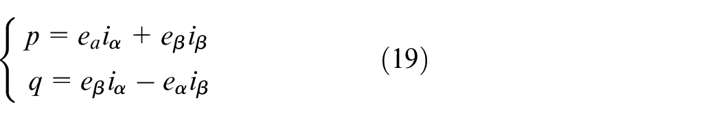
Where
side voltage on
Calculation of equation (20) need to find the expression of voltage and current in the static coordinate system. Therefore, the AC side voltage in the static coordinate system can be expressed as
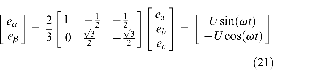
Where
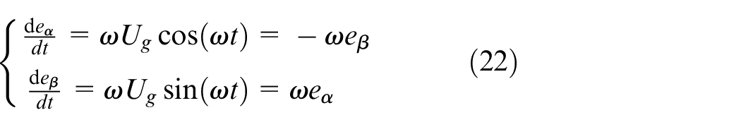
Derivation of equation (21) leads to
In the static coordinate system, line current can be expressed as
Where
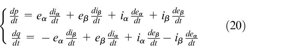
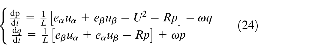
Differential equations of active and reactive power can be obtained by sorting out equations (20)–(23), which can be written as
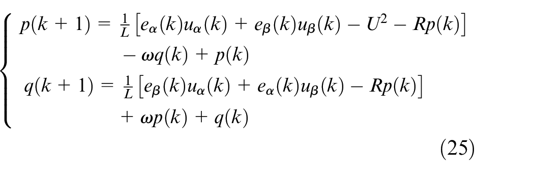
When the sampling frequency is high, equation (24) can be discretized by forward difference method, therefore equation (25) is obtained as
Where
At the time of

Design of MPDPC controller based on FADRC
After the derivative of the third equation in equation (23) is simplified as
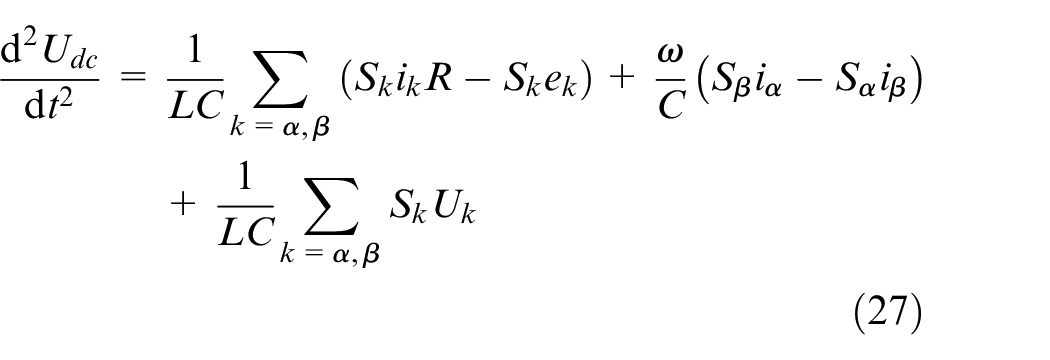
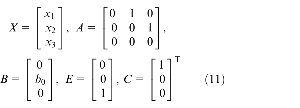
The differential equation of equation (27) is transformed into a state space expression, which can be written as
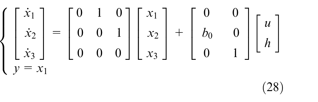
Where
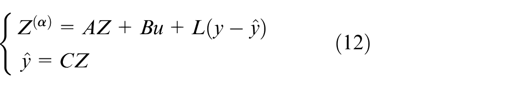
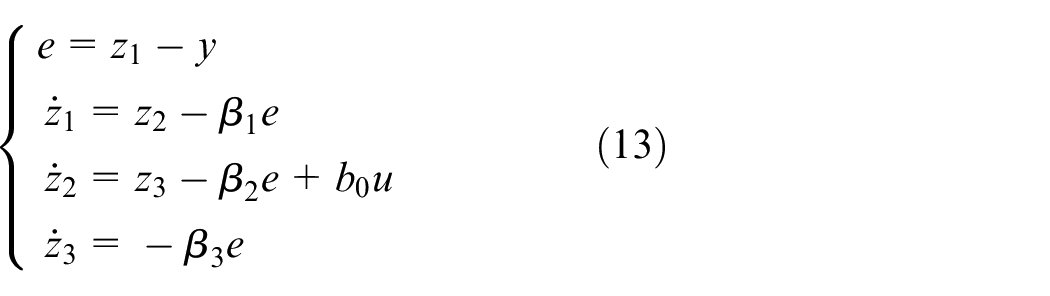
According to equation (13), the third order FESO of the power loop can be written as
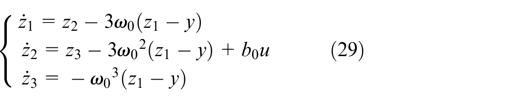
When the parameter
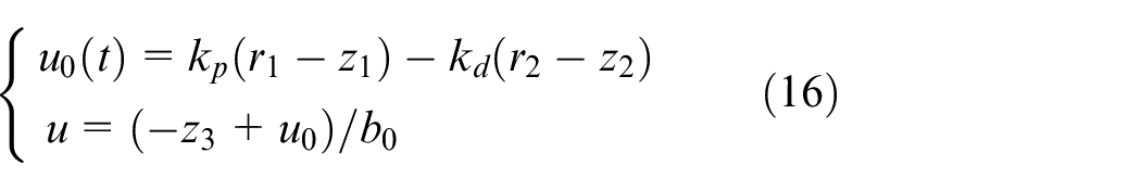
The linear control law can be designed as
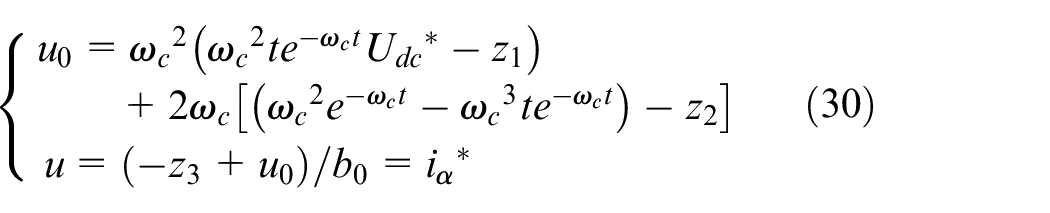
Where
The control structure of the three-phase rectifying converter is based on MPDPC-FADRC, MPDPC-LADRC and MPDPC-PID, respectively, which is illustrated in Figure 5. The voltage and output current of the converter are collected at time
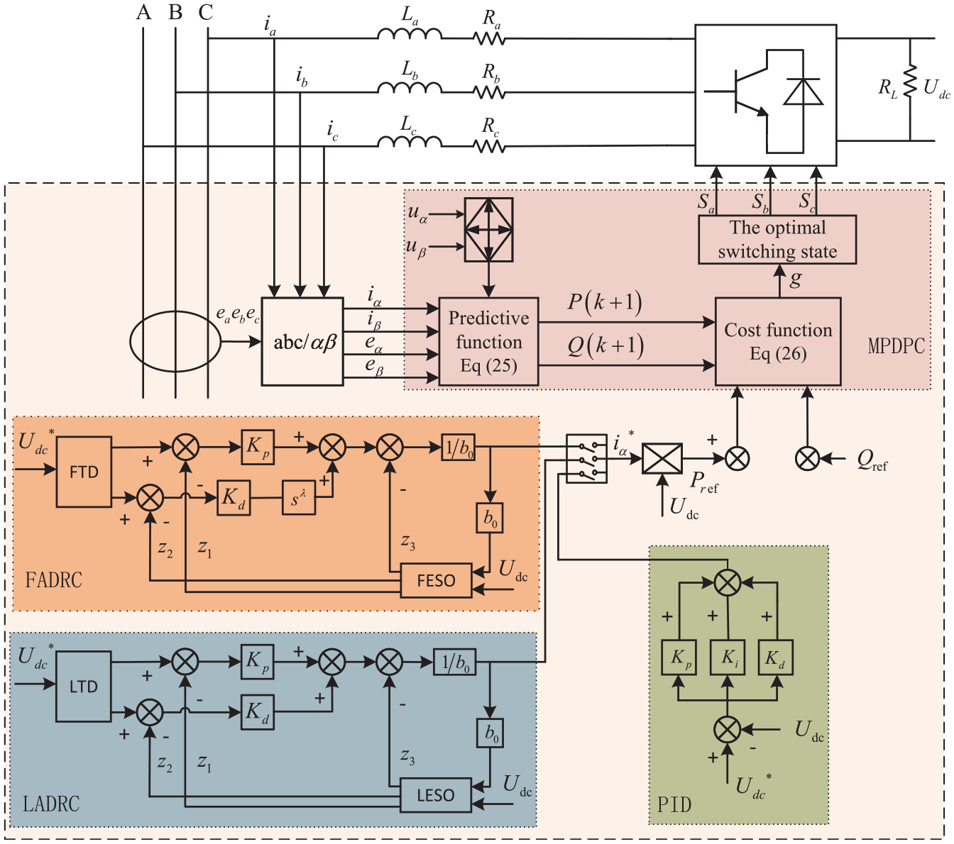
The three-phase rectifying converter based on MPDPC-FADRC, MPDPC-LADRC, and MPDPC-PID.
Analysis of simulation results
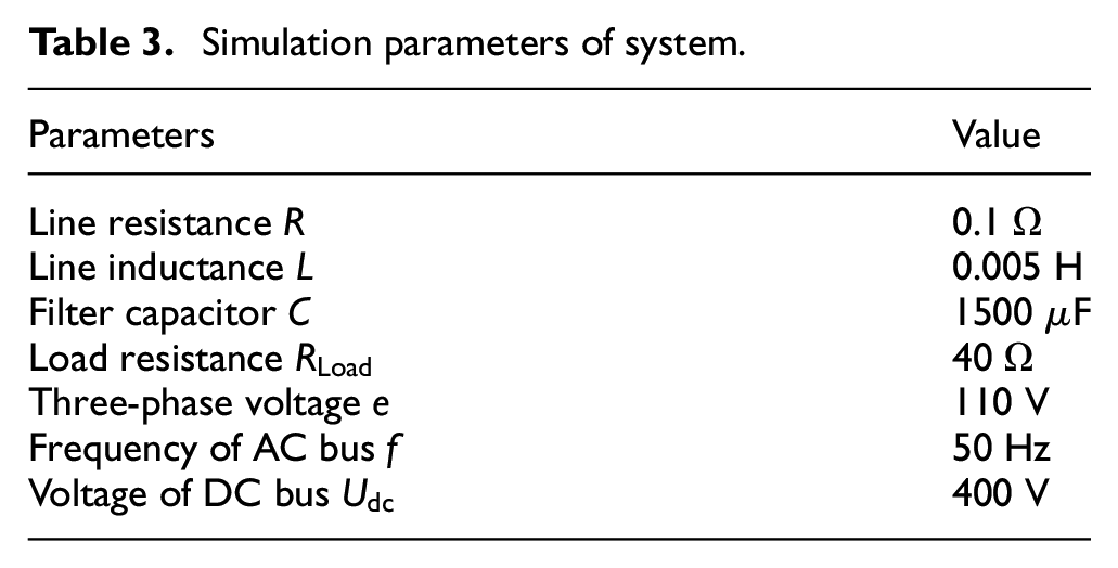
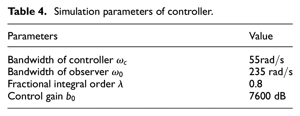
In order to verify the effectiveness of the control strategy proposed in this paper, the system model of three-phase rectifying converter is established in the MATLAB. The main simulation parameters of the system are summarized in Table 3, and the main parameters of the controller are summarized in Table 4.
Simulation parameters of system.
Simulation parameters of controller.
In order to verify that the MPDPC-FADRC strategy has good rapidity and disturbance performance, this paper compares MPDPC-FADRC, MPDPC-PID control, and MPDPC-LADRC. The control effect of MPDPC strategy combined with three control strategies are explored. Then, under the three control strategies, dynamic response speed and steady-state performance of the rectifying converter DC bus voltage are compared and analyzed, for verifying the superior robustness of the MPDPC-FADRC strategy which proposed in this paper. In addition, this paper was also analyzed system characteristic of two conditions, which are voltage drop on the AC side and DC load reducing.
Analysis of simulation in normal operation
In the case of normal operation, other simulation conditions are kept identical, only the control strategy is different. Figures 6 and 7 respectively show the three-phase current and voltage waveform under the MPDPC-FADRC strategy. Figure 8 show the THD index of AC side current under MPDPC-FADRC, respectively. The MPDPC-FADRC strategy which is proposed in this paper can better suppress the current harmonic at the AC side. And the THD index is 4.34% which meets the requirements of power grid.
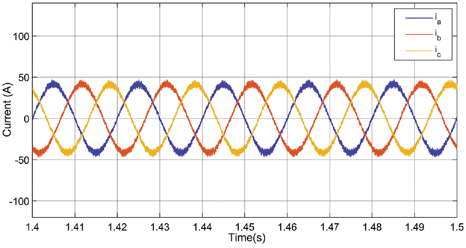
Three-phase current of three-phase rectifying converter.
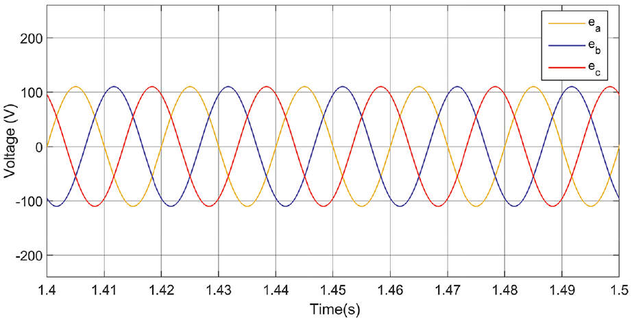
Three-phase voltage of three-phase rectifying converter.
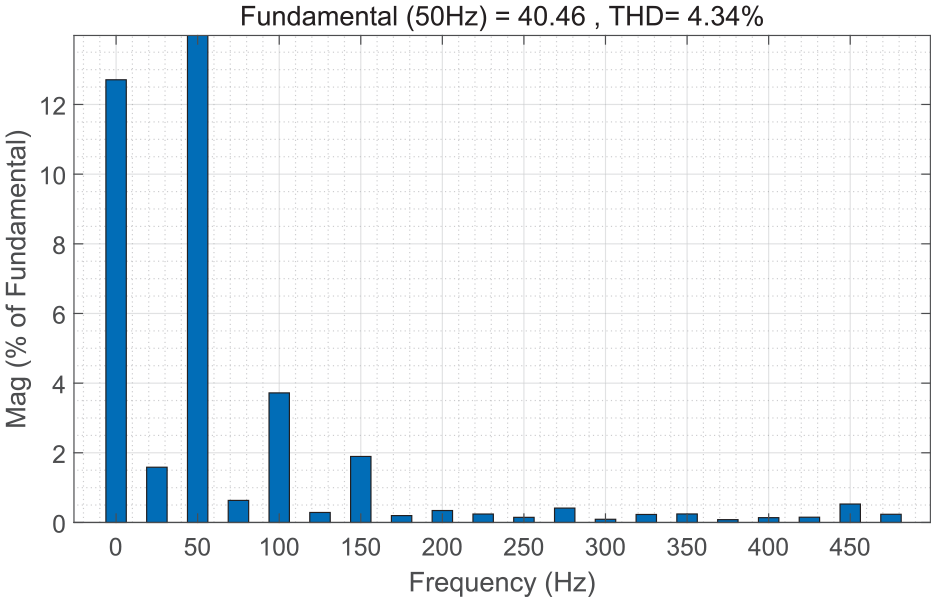
THD index of AC side current under MPDPC-FADRC.
As exhibited in the Figure 9, the comparison of DC bus voltages under three control strategies of MPDPC-FADRC, MPDPC-PID control and MPDPC-LADRC is obtained. It can be observed that the DC bus voltages under three control strategies can achieve basically the same control effect as the given reference value of 400 V. However, the time of reaching stability is different for the DC bus voltage. Under the MPDPC-PID and MPDPC-LADRC control strategies, the time of reaching stability is respectively 1.87 and 0.76 s for the DC bus voltage. Compared with MPDPC-PID and MPDPC-LADRC, the DC bus voltage based on MPDPC-FADRC can stabilize within 0.48 s, and the ripple coefficient can be maintained around 0.02 V.
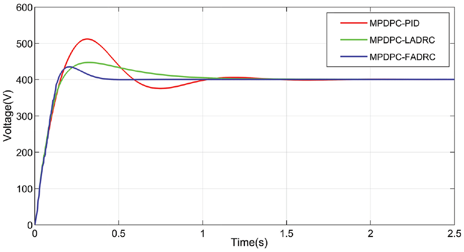
The comparison of DC bus voltage of three-phase rectifying converter.
Figure 10 illustrate the measurement values of active and reactive power based on MPDPC-FADRC strategy. The given active power
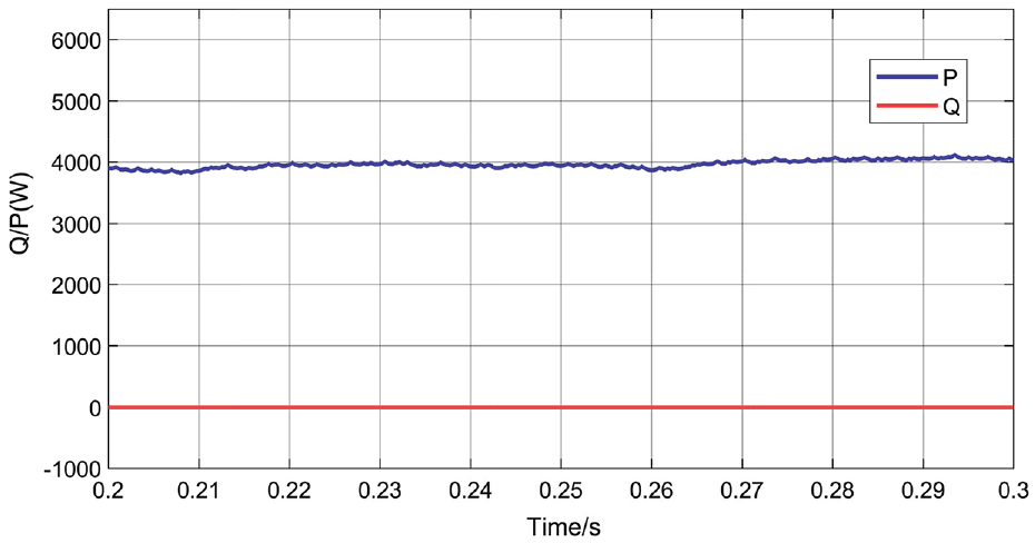
MPDPC-FADRC active and reactive power measurements.
Simulation experiment analysis under distribution
The symmetrical voltage drops of 25% on the AC
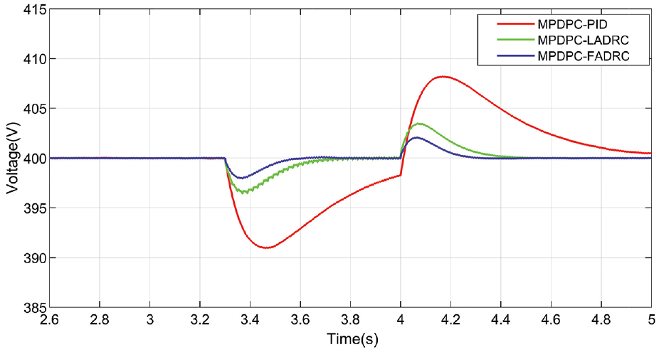
The voltage symmetry drop amount caused by the fault was set as 25%. The fault starts at time of 3.3 s and ends at time of 4 s, therefore, the fault remained time was 0.7 s. When other simulation conditions were identical, the voltage waveforms of the DC bus were compared under the three control strategies. Figure 11 shows the comparison of DC bus voltage waveforms of three control strategies under fault of voltage symmetry drops 25% on AC side.
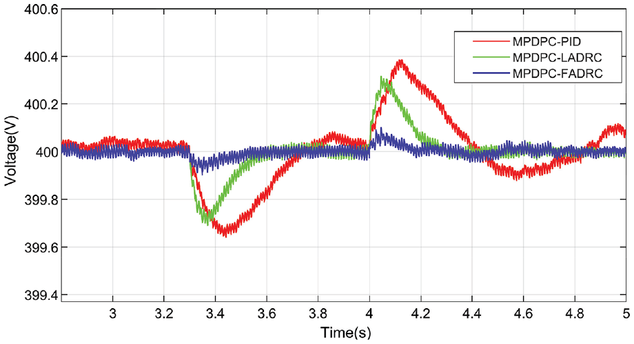
The bus voltage of DC side under the fault of voltage symmetry drops 25%.
When the voltage of AC side suddenly decreases to 75%, the DC bus voltage decreases by 0.58 V under the MPDPC- PID control strategy, and the DC bus voltage can hardly reach stability within the experimental time. When decreases to 75%, the DC bus voltage decreases by 0.58 V under the MPDPC-PID control strategy, and the DC bus voltage can hardly reach stability within the experimental time. Under MPDPC-LADRC control strategy, the DC bus voltage decreases by 0.47 V and the voltage returns to steady state in 0.44 s when the fault occurred. Under MPDPC-FADRC strategy, the bus voltage is only reduced by 0.07 V, which can not only restore the voltage to a stable state in 0.33 s, but also have higher steady-state precision after voltage recovery. Compared with MPDPC-PID control and MPDPC-LADRC, the DC bus voltage of FADRC only increases by 0.08 V When the AC side voltage begins to recover. And the DC bus voltage wave of MPDPC-PID control and MPDPC-LADRC are 0.39 and 0.31, respectively. Therefore, it can be concluded that the MPDPC-FADRC control on three-phase rectifying converter is not easily affected by the voltage fluctuation of the AC side, consequently, the voltage fluctuation is less obvious when the fault occurs.
The load of DC side increased or decreased by 50%
The load of DC side increased or decreased caused by the fault was set as 50%. The fault starts at time of 3.3 s and end at time of 4 s, therefore, the fault remained time was 0.7 s. When other simulation conditions were identical, the voltage waveforms of the DC bus were compared under the three control strategies. Figure 12 shows the comparison of bus voltage waveforms of three control strategies under the fault of increasing or decreasing load of 50%. When the load at the DC side suddenly decreases by 50%, the voltage of AC bus will decrease due to the sudden reduction of the power at the load side. Under the MPDPC-PID control, the voltage of the DC bus drops to 386 V at most, and the bus voltage cannot return to steady state after 0.7 s; under MPDPC-LADRC control strategy, the voltage of the DC bus drops to 396 V, and the voltage returns to steady state at 3.88 s. However, under MPDPC-FADRC strategy, the voltage of the DC bus only drops to 398 V, which can not only restore the voltage to a stable state in 3.64 s, but also have higher steady-state precision after voltage recovery. When the DC side of the load starts to recover, the voltage of the DC bus drops to the DC bus voltage increases only by 2 V under the MPDPC-FADRC, however, the MPDPC-PID and MPDPC-LADRC are 12 and 4.5 V, respectively.
The bus voltage of DC side under the fault of increasing or decreasing load of 50%.
Therefore, under the same operating conditions, the MPDPC-FADRC can significantly reduce the voltage fluctuation of the DC side, shorten the transition time of the system, and improve the tracking performance and disturbance attenuation ability of the system. The MPDPC-FADRC strategy can make the rectifying converter respond to the external disturbance quickly and stabilize the DC bus voltage accurately to the reference value.
Conclusions
In order to further remedy the deficiency of weaker robustness, weaker ADRC and lower response speed of the MPDPC-PID strategy of three-phase rectifying converter, this paper respectively proposed MPDPC-LADRC strategy and MPDPC-FADRC strategy. Simulations results verify that under operational scenarios of the symmetrical voltage drops on the AC and the load change of DC side, compared with MPDPC-PID control and MPDPC-LADRC, MPDPC-FADRC can more quickly track the load change and deal with the disturbance of unbalanced voltage on AC side in time. Therefore, the MPDPC-FADRC strategy has best disturbance rejection capability, robustness and rapidity, and it can significantly improve steady state accuracy of the voltage of DC bus. And this study can provide a significance reference for practical application when designing control strategies of the three-phase rectifying converter.
Footnotes
Declaration of conflicting interests
The author(s) declared no potential conflicts of interest with respect to the research, authorship, and/or publication of this article.
Funding
The author(s) disclosed receipt of the following financial support for the research, authorship, and/or publication of this article: The paper was supported by the Education Department of Jilin Province (Grant JJKH20200044KJ) and Project of Beihua University (Grant 201901012). Research and Innovation Project of Beihua University (Grant: [2021] 008).