
Abstract
This paper presents a new direct torque and flux control method for induction motor fed from Photovoltaic (PV) System. The proposed strategy is based on Stator Field Orientation with deadbeat torque and flux control. The deedbeat control approach is based on establishing the voltage vector necessary to supply the motor and reach the electromagnetic torque and flux references at the end of a sampling period T. In order to create the voltage shape and frequency to control the induction motor, the inverter is supplied by a DC voltage extracted from a PV system. Model Reference Adaptive System and Luenberger Observer are designed to determine the stator flux and rotor speed. Extensive simulation work was carried out, which demonstrated that the proposed strategy is capable of reducing the torque and flux ripples and maintaining a constant switching frequency.
Keywords
Introduction
Solar still occupies a minimal place among the Renewable Energies but has experienced solid growth in recent years. 1 Photovoltaic (PV) solar energy converts sunlight into electricity in semiconductor materials like silicon or is covered with a thin metal layer. 2 These photosensitive materials have the property of releasing their electrons under the influence of external energy.
The applications of solar photovoltaic energy are highly varied. In general, they can be classified into two main sections: Isolated and connected systems to the network. The diversity of applications for PV energy is almost endless. Nevertheless, we highlight a few examples: lighting, agricultural and livestock systems, rural electrification, telecommunications, etc.
Several research works have dealt with the association of electric machines and solar systems, which find their application in some sectors such as agriculture and industry. Particular fields of application require a variation in the speed of an electric motor either to improve its operation or its efficiency.
Direct torque control (DTC) or direct self-control (DSC) is a method of controlling electric variable speed drives. In classic DTC, torque and flux generated by the motor can be controlled using a hysteresis controller, which allows fast response and good dynamic performance of the controlled quantities. 3,4 However, this strategy has two drawbacks major: on the one hand, the switching frequency is highly variable, and on the other hand, the amplitude of the ripples torque and stator flux remains poorly controlled in the entire speed range due to the use of hysteresis controllers and tables switching. 5 It should be noted that the ripples of the torque generate additional noise and vibrations and therefore cause fatigue in the rotating shaft. Therefore, several techniques are used in the literature to overcome the drawback of classical DTC. Among the proposed solutions, we cite the intelligent predictive torque controller, 6 DTC based on variable band hysteresis regulators, 7 fuzzy logic techniques, 8 12-Sector Methodology of Torque Ripple Reduction, 9 Adaptive neural network-based controller. 10 These control techniques generally give complex configurations. In Refs. 11 and 12, the optimized switching instant is calculated according to a law of minimization of torque oscillations, but the accomplishment is more complicated and requires many commutations. In order to overcome constraints of calculation times and improve the performance of the classic DTC drive, we have developed a new direct torque control based on a deadbeat solution. This method directly controls torque and stator flux (fast control) in a similar way to the traditional DTC strategy. The necessary voltage vectors for the electric inverter are calculated in a stator flux reference frame to eliminate flux and torque errors in one sample period. These voltage vectors are based on the estimation of the required switching instants applied to the inverter switches which will supply the electric motor.
To perform deadbeat direct torque and flux control for induction motors (IMs), it is necessary to accurately know the magnitude and angular position of the controlled flux. There has been much research on designing sensorless control schemes over the last 10 years. Most of these schemes are based on the Model Reference Adaptive System (MRAS).
It consists of two distinct models: a reference and an adjustment model with an adaptation mechanism. The block “reference model” represents the actual system whose values are unknown. A model with adjustable parameters has the same structure as reference one, except that its parameters are adjustable instead of unknown. For time-invariant systems with known parameters, the Luenberger observer and its extensions are used in the deterministic case when no random noise is present. The Luenberger observer’s equation is based on adjusting the estimated output’s current state by an amount proportional to the prediction error defined as the estimate of the output minus the measurement of the output as it is. This adjustment ensures that the observer will remain stable and converge moderately quickly. In addition, when the system’s parameters are unknown or time-varying, an adaptive observer must be included. Adaptive observers must also estimate system parameters in addition to estimating system states. Many contributions have been devoted to the observers' synthesis for nonlinear systems, as indicated in the literature review by the comprehensive syntheses: Refs. 13, 14, 15, and 16.
In this work, we used Luenberger Observer to estimate the current, stator, and rotor fluxes. 17–19 The adaptive observer known as the MRAS is designed to estimate the rotor speed. 20,21 This paper is subdivided into the following sections: a general introduction in the first section. A brief description of the induction motor modeling is given in the second section. The third section deals with the deadbeat control strategy. The flux and speed estimation will be detailed in the fourth section. The simulation results will be exposed and detailed in the fifth section. The last part of this paper will be devoted to a general conclusion.
Solar photovoltaic cell model
PV modules are composed of multiple solar cells that are connected in series and in parallel to generate the desired voltage and current. Cells in solar panels are essentially p-n semiconductor junctions. A dc current is generated by exposing them to light. The single-diode model of Figure 1 is used in this document. With its basic structure, this model provides a good balance of simplicity and precision. Equivalent circuit of solar cell.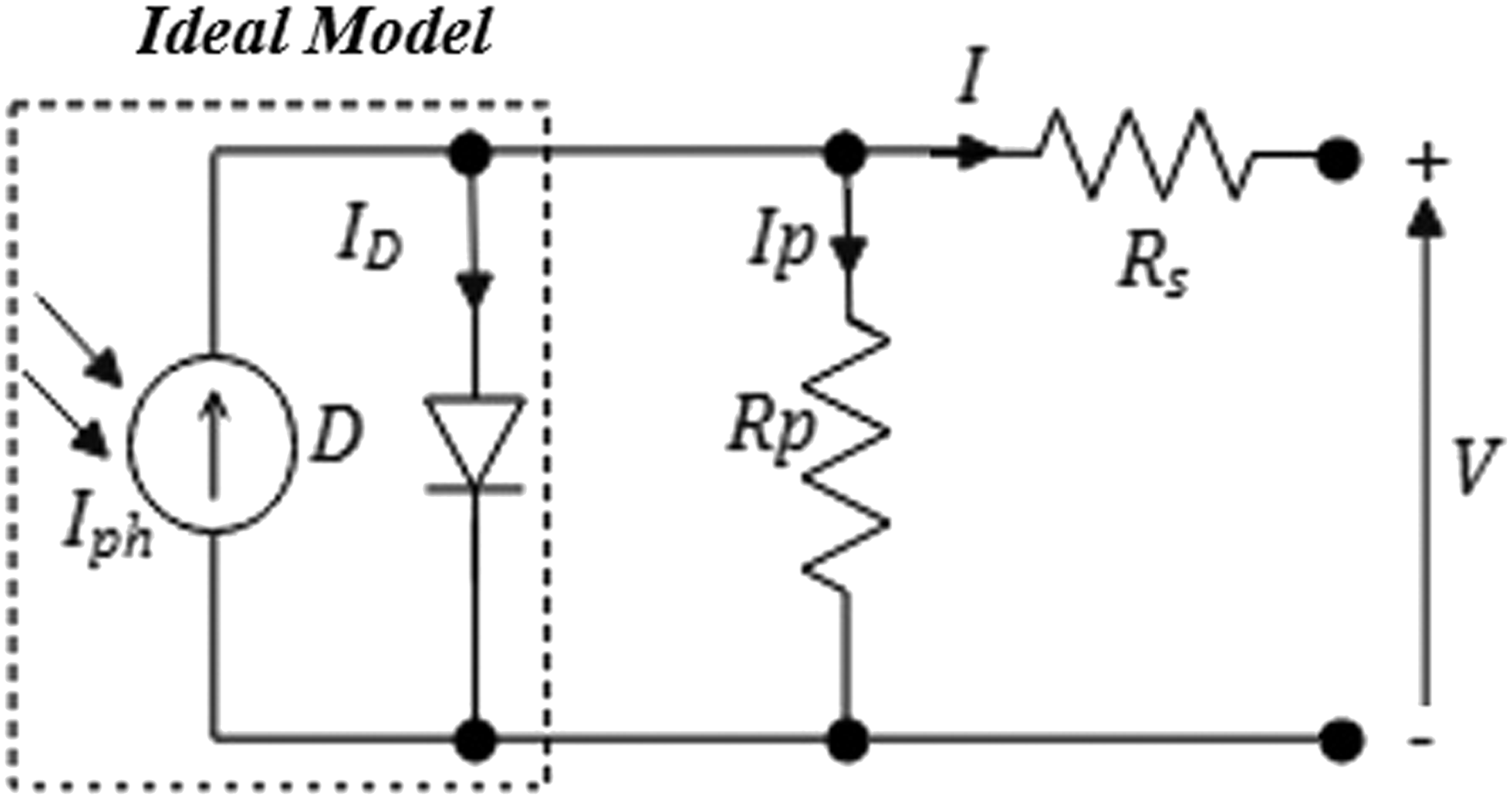
The equivalent circuit of the general cell model is given by Figure 1.
With: Iph a photo-current, Rp parallel resistance, Rs series resistance, ID diode current.
According to Kirchhoff’s law in Figure 1, the current can be calculated as follows

Iph : the current generated by light or photocurrent.
Ip : the current flowing in the parallel resistor.
ID : the current of the diode.
The following equation gives the diode’s current as a function of saturation current
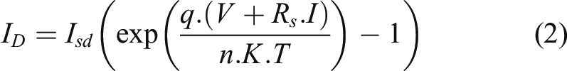
I sd the reverse saturation current in amperes (A),
q the electron charge (1.6 × 10⁻¹⁹ C),
K the Boltzmann constant (1.38 × 10⁻²³ J/K),
T the cell temperature in Kelvin (K)
n the ideal factor.
In equation (1), we replace the voltage-current characteristic equation of a solar cell, so we get
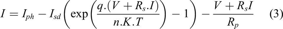
From equation (3), we can deduce the voltage-current characteristic of a PV module as follows
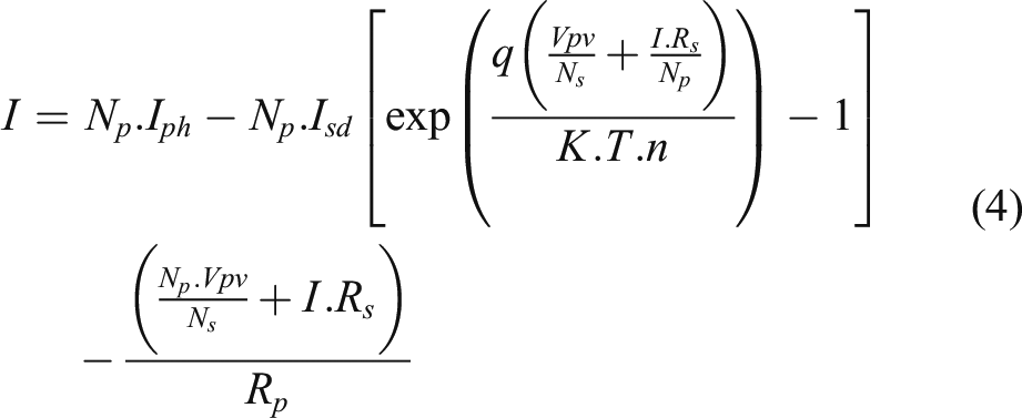
Parameters of photovoltaic module “SunPower SPR-X20-250-BLK”.
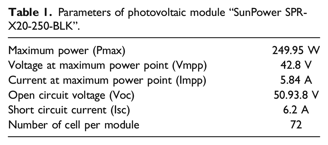
Figure 2 shows photovoltaic generator characteristic curves (16 Modules: two strings of eight photovoltaic modules connected in parallel) Photovoltaic generator characteristic curves.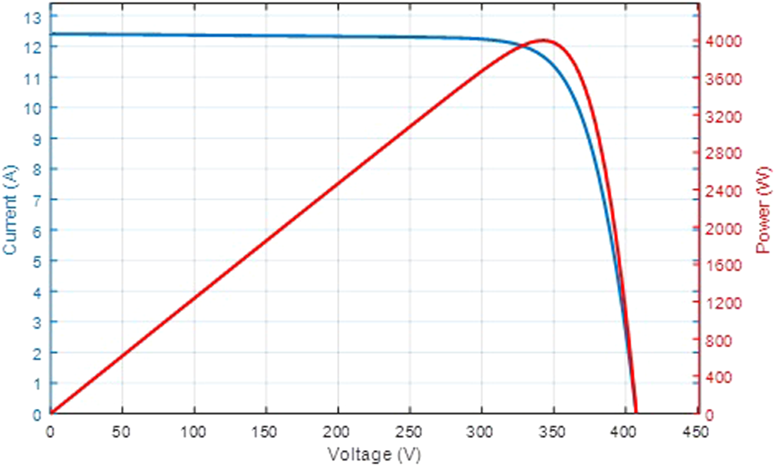
Deadbeat control
The Deadbeat control method is part of the class of so-called “finite settling time” methods. The idea is to design a corrector which responds in finite absolute time (i.e., including the behavior between sampling times), while ensuring a zero static error concerning a particular input. 22,23 The principle of the deadbeat strategy will be applied to direct Torque and Flux Control of the induction motor.
The stator voltage vector required to reject the flux and torque errors in one switching period is calculated in a stator flux reference frame. This estimated voltage vector will be taken as a reference to a space vector PWM scheme. 24 The Deadbeat flux and torque control are described in sections B and C. The basic induction motor model will be detailed in section A.
Basic induction motor model
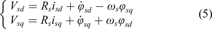
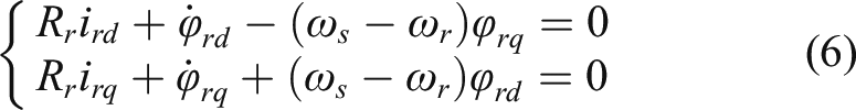
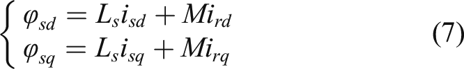
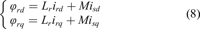
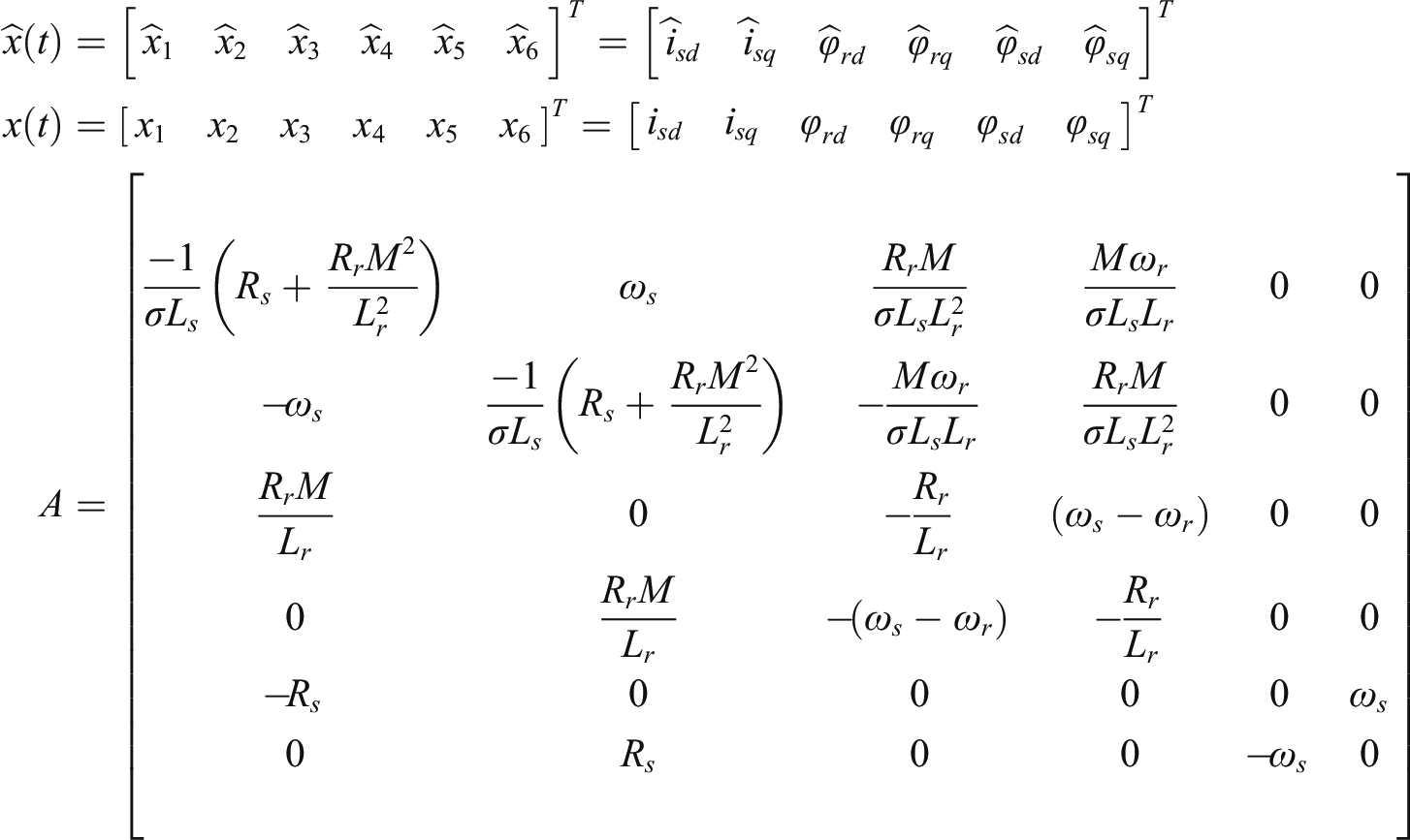
The following equations describe the dynamic behavior of an induction machine written in the Park reference frame rotating at ωs . 25
The stator voltage vector required to reject the flux and torque errors in one switching period is calculated in a stator flux reference frame. This estimated voltage vector will be taken as a reference to a space vector PWM scheme. 24 The Deadbeat flux and torque control are described in sections A and B.
Flux control
The flux control consists of aligning the stator flux along the d axis of the turning reference frame. We therefore: φsd = φs and φsq = 0
The dynamics of stator flux can only be determined by the voltage component of the d axis stator
Equation (9) can be written as a discrete forward difference equation
It is essential to recognize the following factors when determining a deadbeat flux control 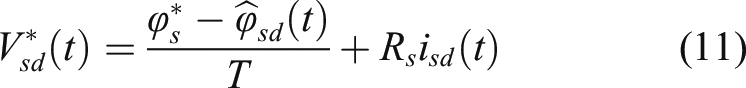
Torque control
Assuming the alignment of the stator flux along the d axis, the expression of electromagnetic torque is defined as
The torque is only dependent on the q axis current if the flux is conveniently controlled. Clearly, the quadrature component of equation (13) shows that this current is strongly correlated with synchronous speed.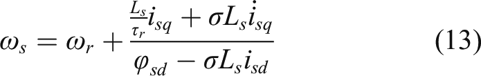
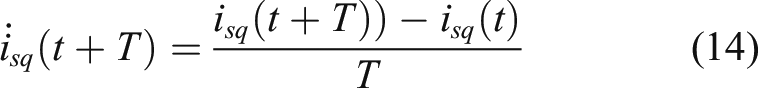
Appling the deadbeat control of the electromagnetic torque, the reference value of torque will be equal to the estimated value in the next sampling time
Combining equations (14)–(16) gives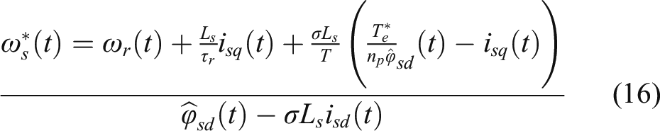
As a result, the q axis voltage component of equation (5) can be given by the following equation
The equations (11) and (17) represent the controlled voltage values to the machine. Using the deadbeat control to the flux and torque allow having the respective commanded voltage values at the next sampling instant. In order to implement this control strategy, it is necessary to measure stator voltages and currents.
Figure 3 shows the block diagram of the direct torque and flux control (DTFC) scheme for speed sensorless induction motor drives. Block diagram of a DTFC strategy.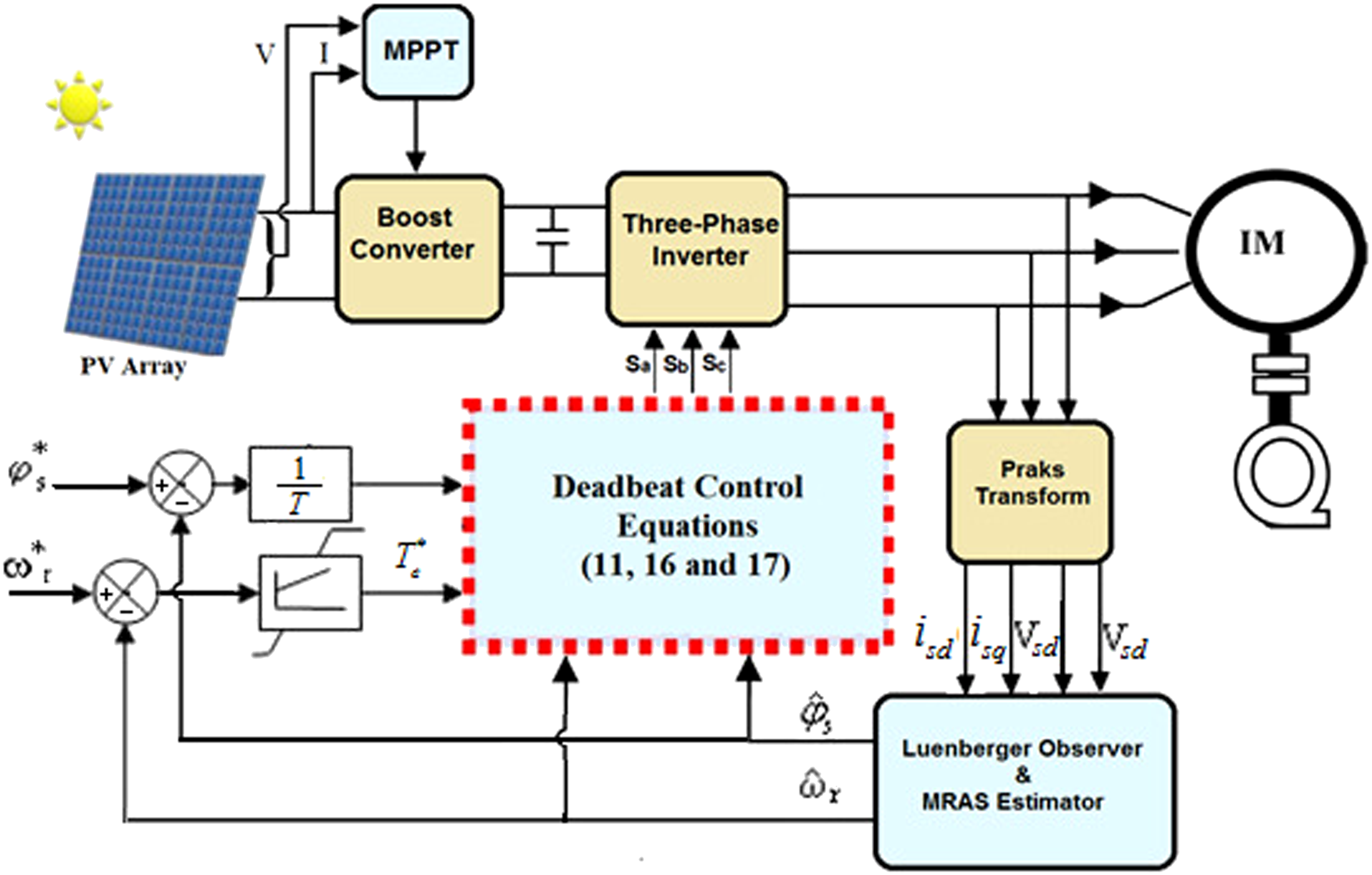
Flux and speed estimation
The performance of this proposed control strategy is sensitive to estimated flux and speed estimation. A linear observer may not be able to provide the required performance over the induction motor’s entire operating range, due to its nonlinearity.
We distinguish several types of the nonlinear observer such as extended Kalman filters, 26 high gain observers, 27 and extended Luenberger observer, 28 In this work the nonlinear Luenberger observer is established from the model of machine behavior which is based on observation techniques derived from automation.
Luenberger Observer (LO) is one of the most basic and extensively used linear observers. It ensures that the system converges to the real state. LO also allows us to employ simpler models while still achieving good results by selecting the right gain. The removal of speed sensors, on the other hand, reduces system dependability and driving cost. In this research, a reference adaptive system model MRAS is used for the estimation of the induction motor rotor. The adaptation law to estimate the speed uses the cross-product of the current error vector and the observed flux vectors. The fluxes used for speed estimation are obtained by a full-order Luenberger observer, taking the difference between measured and estimated stator currents to improve the observer dynamic response.
The Luenberger observer
The Luenberger Observe used in this paper is a deterministic observer, which is well adapted to a nonlinear, time-variant deterministic system. It uses the errors of the estimated variables compared with the actual variables to correct the errors of the estimated state variables. The basic equation of Luenberger observer is given by the following relation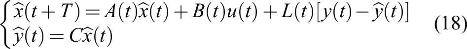
The input variables
The output variables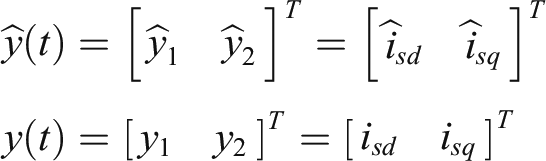
The observer gain matrix L must be chosen in such a way that all eigenvalues
The observer gain matrix must be adapted at each sampling time because the elements of A depend on the motor speed. The gain of the feedback matrix is calculated using the (LQR) principle, given by the following relation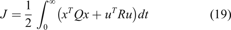
The parameter k denotes the optimal linear state feedback gain.
P is the Riccati equation solution defined as
To guarantee the stability of the matrix
Model reference adaptive system
Traditional methods of speed sensorless drive use stator voltages and currents to estimate flux and slip speed. However, this estimations technique allows a large error, especially at low speeds.
MRAS techniques proved to be an accurate induction motor speed estimation. 21
MRAS has been demonstrated to be a reliable method for estimating induction motor speed.
The reference model defined as the desired performance allows MRAS technique to achieve robust and high performance. The induction motor model was taken as the reference model and Luenberger observer as the adjustable model to obtain two estimates for the rotor flux. Then, from the two rotor flux estimates, the adaptation law to observe the speed uses the cross product of the current error vector and the observed rotor flux vector. The principle of adaptive mechanism is presented in equation (22)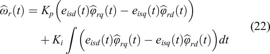
Simulation results
Digital simulations using the Matlab/Simulink Package were used to demonstrate the efficiency of the proposed strategy.
In order to prove the effectiveness of the proposed method, digital simulations based on Matlab/Simulink Package have been carried.
Figures 4–10 show respectively simulation results of the rotor speed, torque, fluxes, stator currents and voltages of the proposed method. Torque and flux control dynamic response is tested by applying constant reference values (at a time t = 0.6 s then TL
= 6 N.m, at a time t = 1 s then TL
= −6 N.m, at a time t = 2 s then TL
= −6 N.m, at a time t = 2.3 s then TL
= 6 N.m). The stator reference flux is fixed at the nominal one Rotor speed response. Electromagnetic torque response. Stator flux response. Stator flux vector trajectory. Stator voltage response. Stator current response. Stator current and voltage response in a rotating α-β reference frame. Block diagram of the model reference adaptive system observer.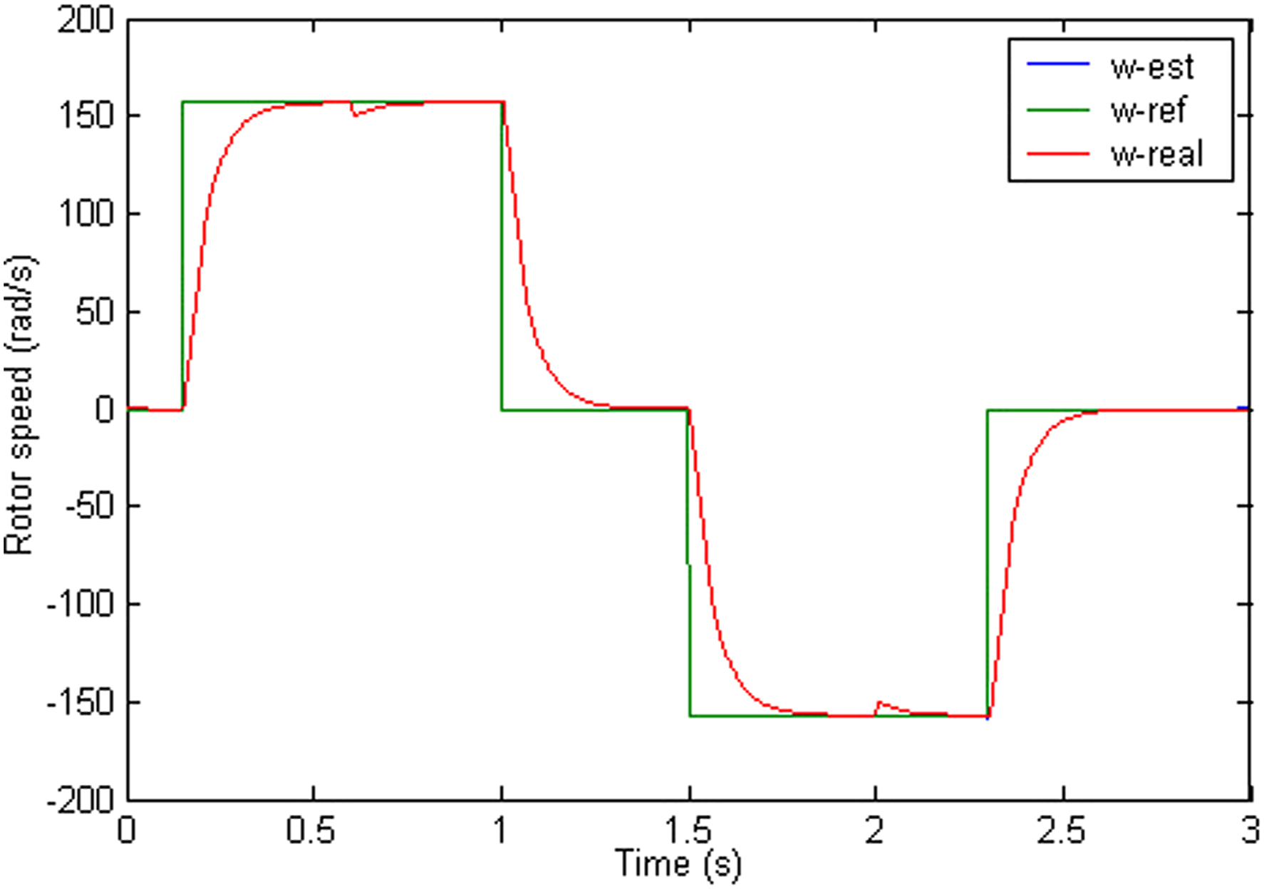
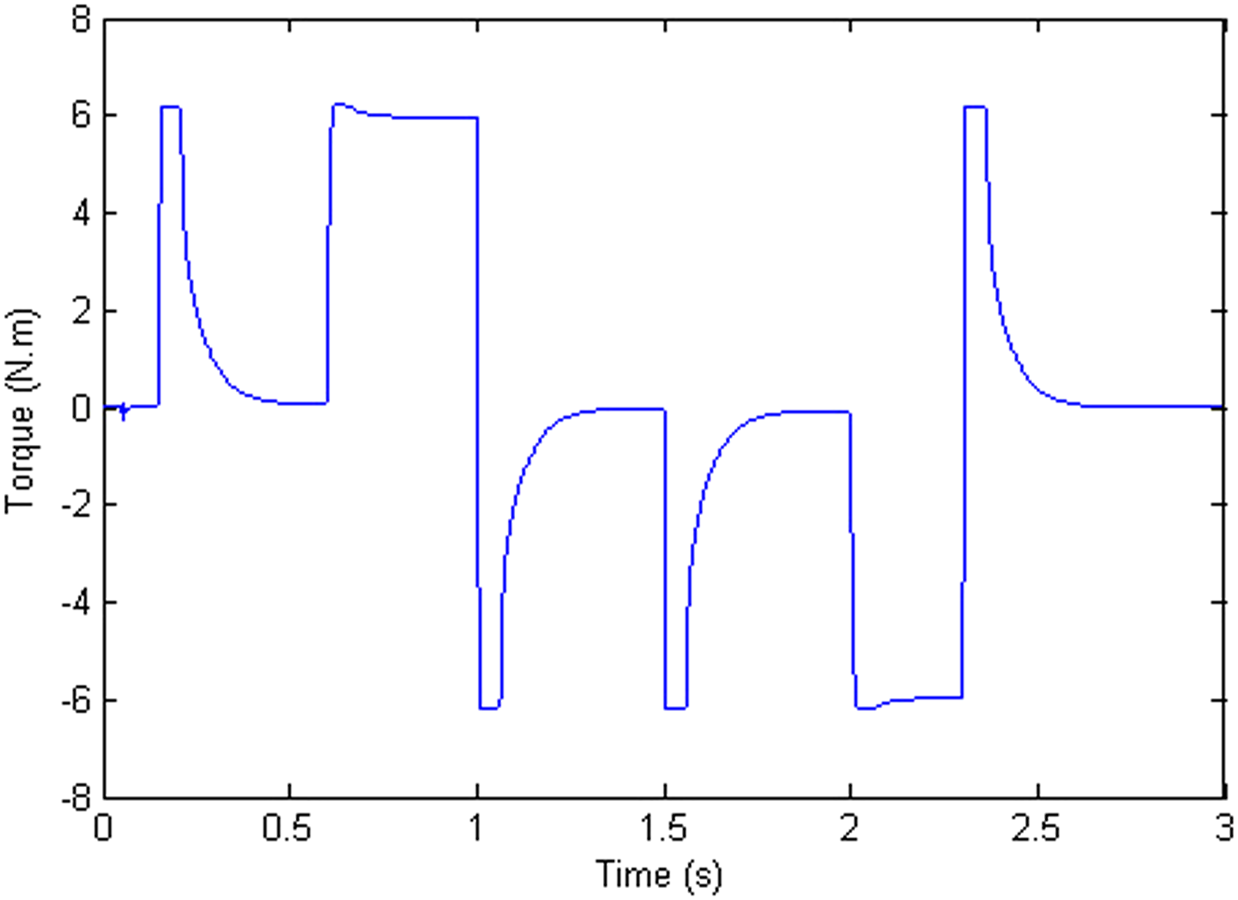
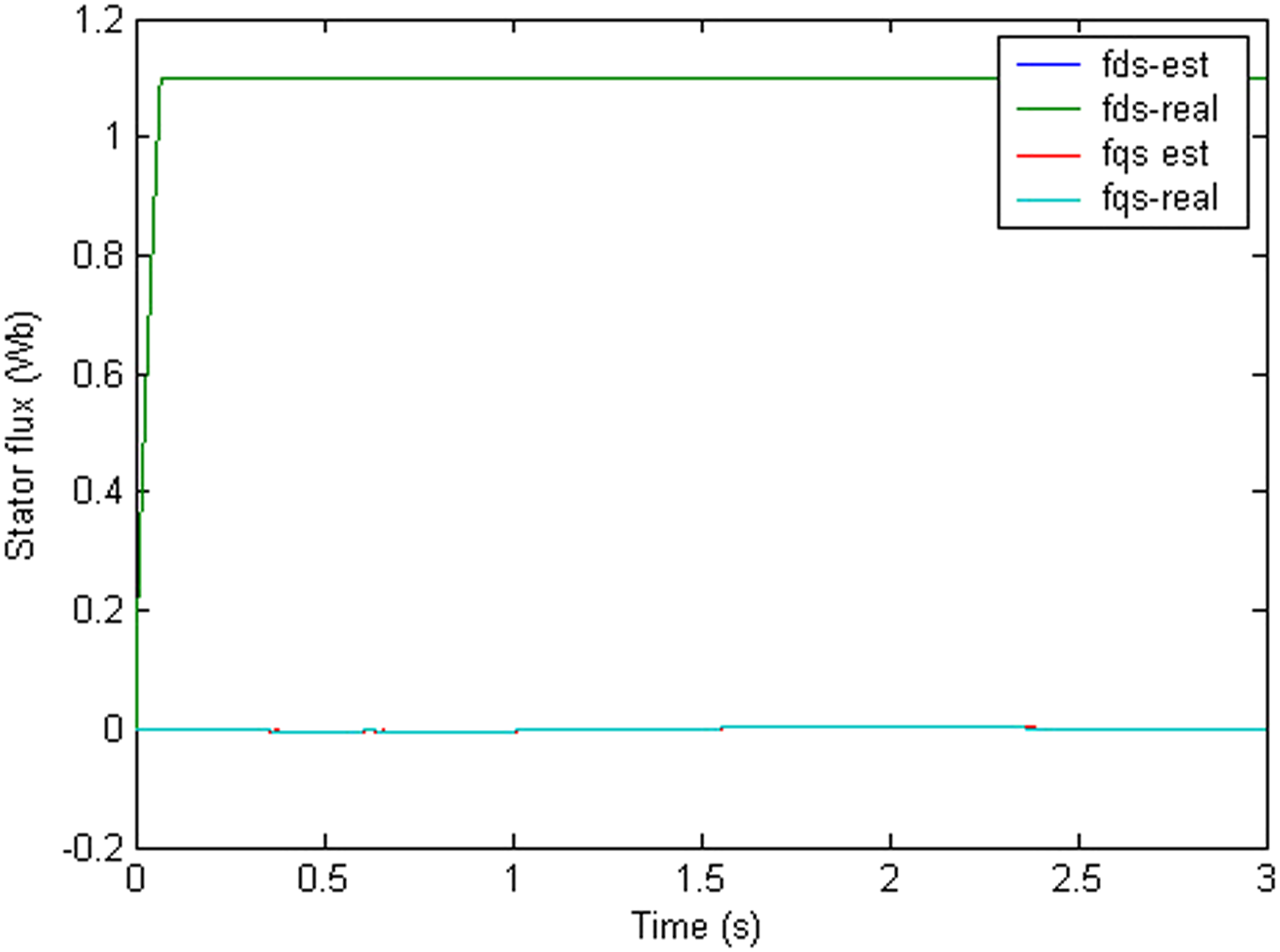
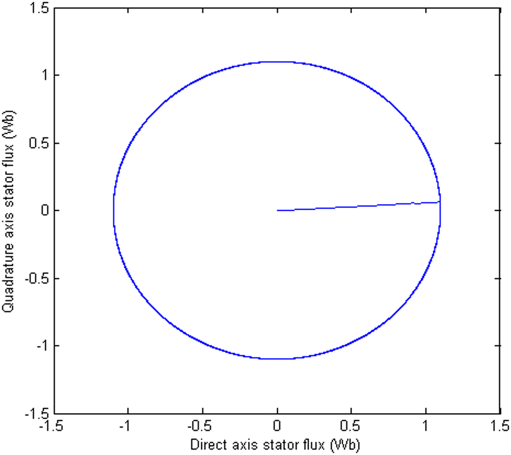
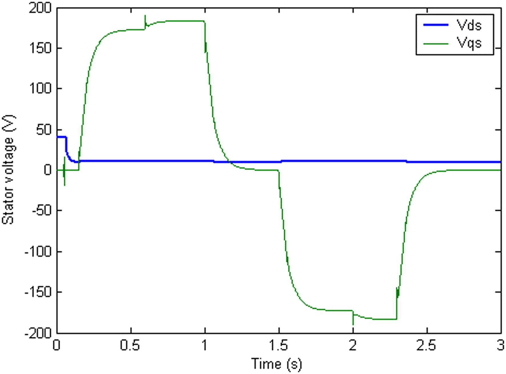
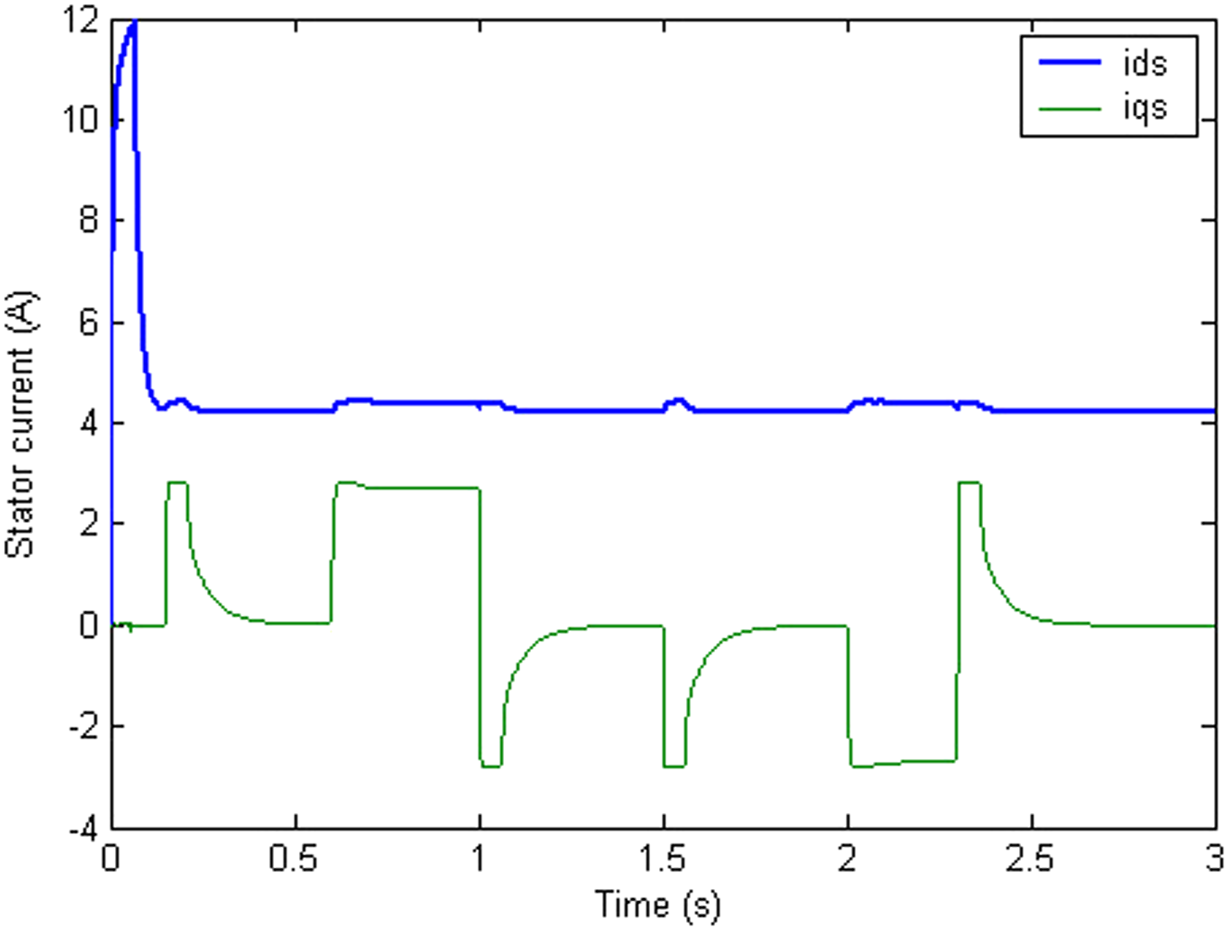
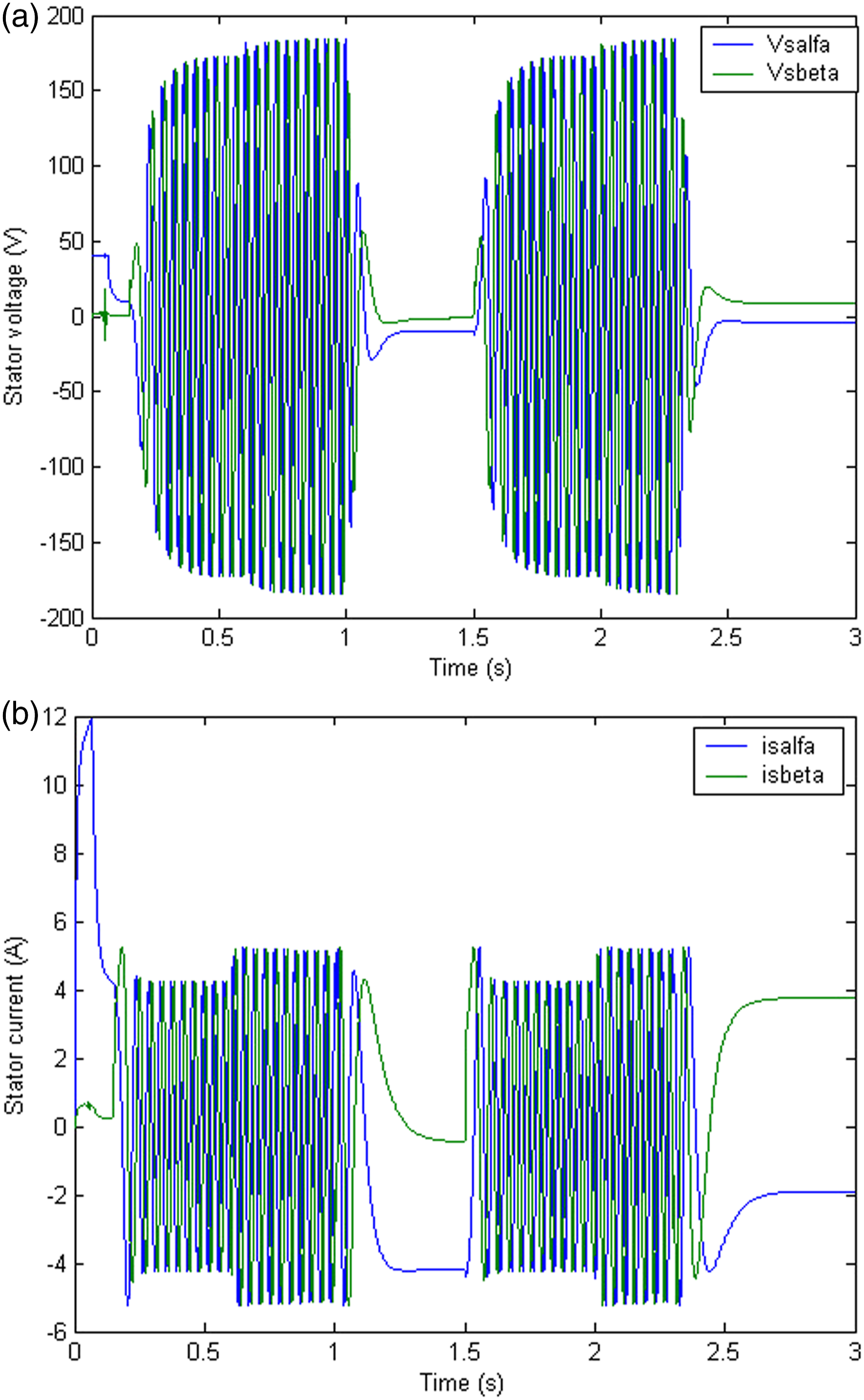
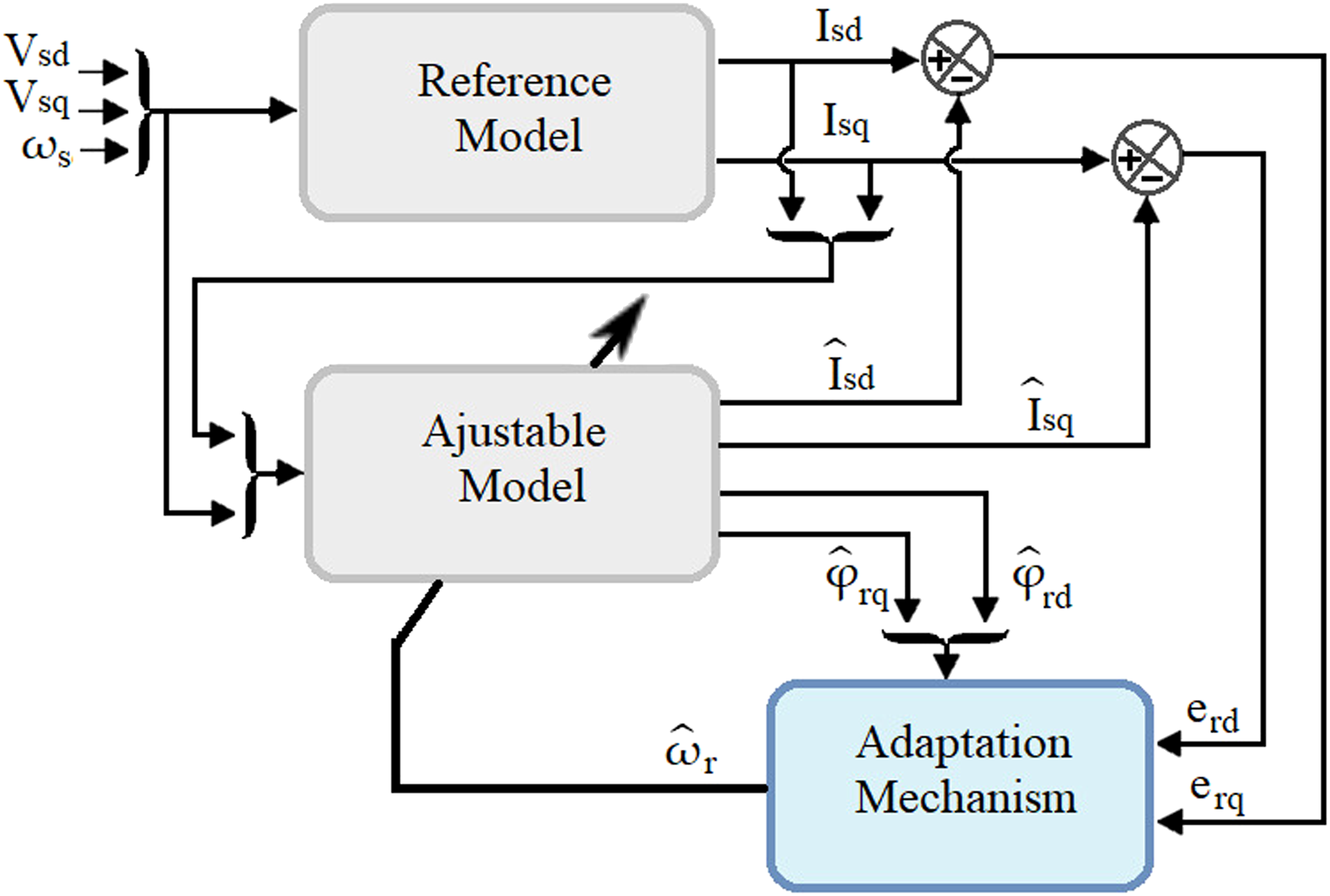
Figure 5 illustrates the result simulation of the torque dynamic response of the proposed drive. It has been confirmed that the torque transient response is good. Despite the low switching frequency, torque oscillations are shown to be very low. As can be seen, the electromagnetic torque closely follows the load steps.
Figure 6 gives the d-q components of the real and estimated stator flux vector. The result clearly shows that the Luenberger observer gives a good estimation for stator flux. It’s clear that flux is unaffected by torque fluctuations (decoupling machine is established), and the estimated magnitude stator flux tracks the required value.
The evolution of the stator current and voltage in d-q and α-β rotating reference frames are shown in Figures 8–10.
The maximum electrical power that the photovoltaic generator can provide in relation to the optimum voltage and current is given by the Figure 12. Electrical characteristics of the photovoltaic generator: (a) Voltage, (b) Current and (c) Power.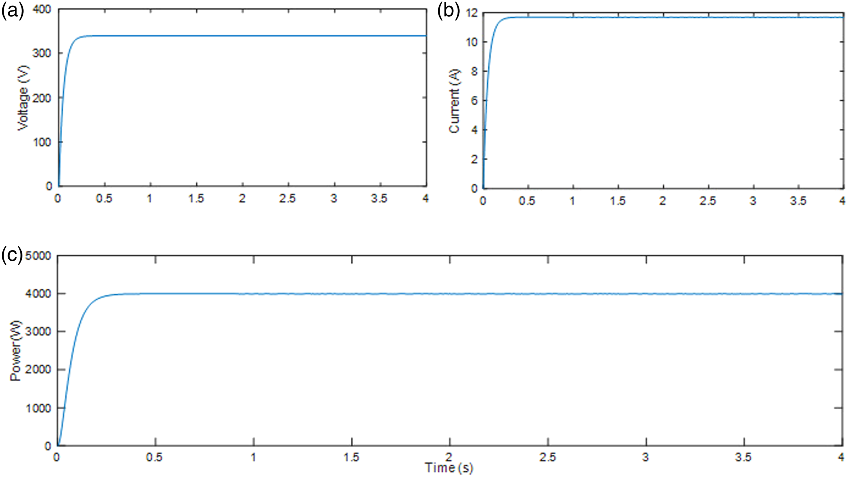
Conclusion
This research proposes a new direct torque and flux control technique, DTFC with speed sensorless applied to the induction motor. This new technique is based on deadbeat direct torque and flux control. The stator voltage vector is calculated using a stator field-oriented strategy for each sampling time. The Luenberger observer and the MRAS estimator are developed and implemented to estimate the flux and the rotor speed. A reasonable estimate for the flux and rotor speed and the effectiveness of the proposed technique is shown in the simulation results. In addition to its simplicity, the proposed approach has increased torque and stator flux performance.
Footnotes
Acknowledgements
The author extends his appreciation to the Deputyship for Research& Innovation, Ministry of Education in Saudi Arabia for funding this research work through the project number “IF_2020_NBU_423”. The author gratefully thanks the Prince Faisal bin Khalid bin Sultan Research Chair in Renewable Energy Studies and Applications (PFCRE) at Northern Border University for their support and assistance.
Declaration of conflicting interests
The author(s) declared no potential conflicts of interest with respect to the research, authorship, and/or publication of this article.
Funding
The author(s) disclosed receipt of the following financial support for the research, authorship, and/or publication of this article: This study is supported by Deputyship for Research & Innovation, Ministry of Education in Saudi Arabia (IF_2020_NBU_423).