
Abstract
This study studies a critical issue that linear velocity and steering angular velocity of the wheels of omni-directional mobile robot are easily affected by the unknown external disturbances such as wind direction and road flatness during the visual servoing stabilization task. To overcome such challenging problems, this study proposes a disturbance observer based visual servoing control strategy. In configuration, the controller is divided into two parts: the quasi-min-max model predictive controller is designed to accommodate the state constraint and input constraint of the system, and complete the visual stabilization task without disturbance. A nonlinear disturbance observer is designed to estimate the external disturbance and feedback compensate the effect of the actual disturbance on the wheel speed. The simulation results and real experiments show that the proposed control strategy can stably accomplish the visual servoing stabilization task even with a large external disturbance.
Keywords
Introduction
Visual servoing has always been a hot research field in mobile robot technology,1,2 which mainly controls the position and pose of mobile robots through visual sensor feedback information at the current instance, so that mobile robots can achieve the functions of stabilization, trajectory tracking, and navigation. In recent years, there have been many researches on visual servoing stabilization methods for mobile robots. Liang et al. 3 proposed an adaptive image-based trajectory tracking control scheme for wheeled mobile robots with uncalibrated fixed cameras. Yan et al. 4 developed a hybrid visual trajectory strategy for wheeled mobile robots equipped with vehicle-mounted vision systems, in which 2.5D visual servoing framework was used to enhance trajectory tracking behavior and helped preserve visual objects within the camera’s visual range. In He et al., 5 a model predictive controller design method based on quasi-min-max strategy was proposed for the limited mobile robot visual servoing system to achieve asymptotic stability of the closed-loop vision system of mobile robots.
The above research approaches are based on the mobile robot visual servoing task without considering the disturbance of the external environment. However, in practical situations and applications, the structure of mobile robot is complex, and mobile robot itself is easily affected by the changes of system parameters, coupled with the external environment disturbance, such as external force disturbance, wheel skid, and other factors, which increase the difficulty of mobile robot system control. How to reduce the external disturbance of the system and improve the control of mobile robot have been critically difficult problems in robot control analysis and design. To effectively suppress the influence of disturbance on the system, adaptive control method, disturbance observer method, and the adaptive method combined with the two methods can be adopted.6–8 In recent years, active disturbance rejection control (ADRC) technology has achieved good results in robot control by establishing an observer to estimate disturbances because it does not need an accurate model of the object. Ma et al. 9 estimated the system disturbance through the extended state observer, and introduced the disturbance compensation term into the active disturbance rejection controller, so as to reduce the uncertainty of system parameters and the impact of external disturbances on the system. Wang et al. 10 from Hebei University, China designed an active disturbance rejection controller based on linear extended observer for the unknown wheel sliding and skidding phenomenon of mobile robots, which enabled mobile robots to achieve better trajectory tracking effect. In addition, there is a kind of model-based control technology, such as sliding mode control, which also has good anti-interference effect. In Li et al., 11 in order to overcome the torque disturbance of wheeled mobile robots, a sliding mode speed tracking controller with disturbance observer is proposed in literature, and finally the mobile robot can track the desired path. In Huang et al., 12 a sliding mode control method based on high-order disturbance observer is designed for the general underactuated system to improve the disturbance estimation ability of the underactuated system. However, when the synovial track enters the dead zone, the sliding model controller will be an unpredictable chattering interval. Therefore, Qiu et al. 13 proposed an uncalibrated visual servoing adaptive model predictive control method based on disturbance observer, which solved the visual servoing tasks of mobile robots under the conditions of unknown internal and external parameters of the camera, external interference and system constraints, and improved the anti-interference performance of the system. Yu et al. 14 took the two-wheel differential mobile robot model as the object and designed a predictive control estimation method based on nonlinear disturbance observer to compensate the slow-varying disturbance of the system, and got a good path tracking effect. Sun et al. 15 proposed a model predictive control method for disturbance suppression and designed two disturbance observers, one to estimate the unknown disturbance and the other to compensate for the disturbance of the known harmonic frequency, finally realizing the non-offset tracking of the trajectory. To compensate the external disturbance of the multi-input multi-output robot system, Liu and Liu 16 constructed a nonlinear observer to estimate the disturbance of the external system, and adopted the backstepping method to suppress the disturbance and improve the performance of position tracking. In Chen et al., 17 disturbance estimation technology is comprehensively summarized, including disturbance observer control (DOBC), active Disturbance Rejection control (ADRC), disturbance regulation control (DAC), etc., and the future development direction of disturbance compensation technology is also discussed.
Inspired by the quasi-min-max predictive control method, 5 this paper studies the visual servoing stabilization control problem of omnidirectional mobile robot in the presence of external environmental disturbances. Different from nonholonomic two-wheel differential mobile robot, omnidirectional mobile robot can move 360° in all directions, so it is more suitable for application in the scene with limited range of activities and has greater practical significance. The major contribution of the study can be briefly described below.
This paper establishes completely the error model and kinematics model of omnidirectional mobile robot with three off-centered direction wheels. The full model integrates the omnidirectional wheeled mobile robot and visual system.
In order to improve the effectiveness and robustness of the control, we designed the quasi-min-max MPC based on a non-linear disturbance observer that provided robust performance regardless of the modeling uncertainties and perturbation.
The simulation results show that the proposed strategy has the advantage of anti-disturbance performance.
The rest of this paper is organized as follows. Section “Problem formulation” presents the visual servoing error model and omnidirectional mobile robot kinematics model. Section “Design of control strategy based on disturbance observer” presents the detailed design process based on disturbance observer control strategy. Section “Simulation” shows off the simulation results to demonstrate the performance of the control strategy. Finally, Section “Conclusions” concludes the study.
Problem formulation
Nonholonomic OWMR description
As shown in Figure 1, an omnidirectional wheeled mobile robot (OWMR) is assumed to move in a plane, which is independently driven by three off-centered direction wheels 18 and equipped with a monocular camera above the OWMR. Ow-XwYwZw is the world coordinate frame attached to the ground, Or-XrYrZr is the robot coordinate frame fixed to the OWMR, the origin Or is located at the mass center of the OWMR, Oc-XcYcZc is the camera coordinate frame attached to the camera, the origin Oc is located at the Zr axis of the robot coordinate frame, and the Xc and Yc axes are in the same direction as the Xr and Yr axes. Assuming that the OWMR moves on the plane under the nonholonomic constraints of pure rolling and non-slipping, then the speed and the pose of the omnidirectional mobile robot satisfy the following relationship:
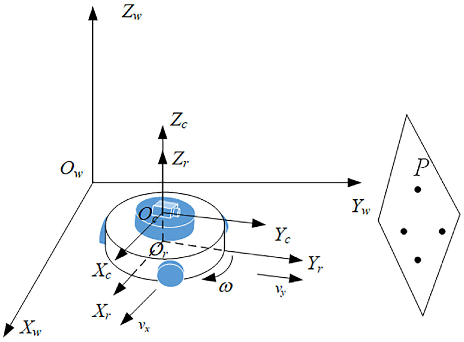
Omnidirectional wheeled mobile robot visual servoing model.
where (x, y) is the coordinates of the robot’s mass center in the world coordinate system, θ is the angle between the world coordinate system and the robot coordinate system, and counterclockwise is positive. q = [x yθ]T is the posture of the mobile robot, vr = [vx vyω]T is the speed of the omnidirectional mobile robot, that is, the control input, vx and vy are the longitudinal and lateral linear velocities of the omnidirectional mobile robot, and ω is the angular velocity of the omnidirectional mobile robot.
Define the coordinates of feature point P in the world coordinate system as (X, Y, Z), in the robot coordinate system as (xr, yr), and in the camera coordinate system as (xc, yc, zc). The equation can be obtained according to the geometric relationship in Figure 1:
Since the feature point P is stationary, X and Y are constants. Taking the derivative of equation (2), and then combining with equation (1) we can obtain the change of robot motion position of feature points in the camera coordinate system, that is, the robot-camera-target model is as follows:
There are various disturbances encountered frequently in the actual environment in the visual servoing task of omnidirectional mobile robot, such as lateral wind, ground slip, and so on, which will affect the linear velocity and angular velocity of mobile robot. When external disturbances are considered, model (3) of the omnidirectional mobile robot system can be written in the following general form:

Where
Visual servoing error model of OWMR
As shown in Figure 1, P is the feature point the world coordinate frame. We assume that (xp, yp) is the image coordinate of the projection point p of feature point P in the image coordinate system, (up, vp) is the corresponding image pixel coordinate, (u0, v0) is the center of the image plane, f is the focal length of the camera. According to the image projection model,19,20 the relationship between the camera coordinate system and the image coordinate system can be derived by

where
By normalizing the image coordinates, we have that
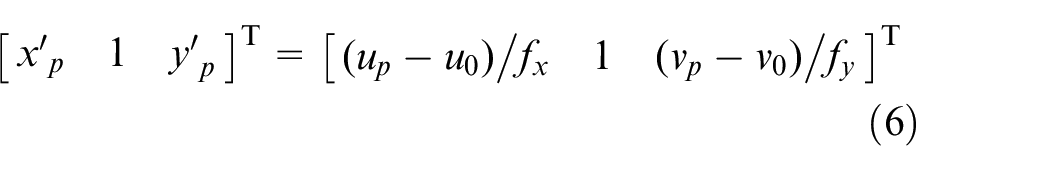
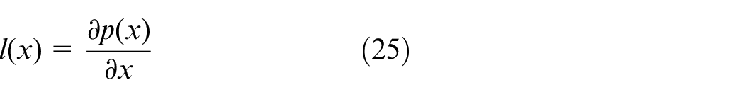
with the normalized image coordinates (xp′, yp′). Taking the derivatives of (6) and combining (5), it is obtained that
Let υc = [vx, vy, vz, ωx, ωy, ω z ]T be the velocity of the camera on the robot. Since the robot moves in plane, that is, vz = ωx = ωy = 0 and ωz = ω, the motion velocity of p is obtained by
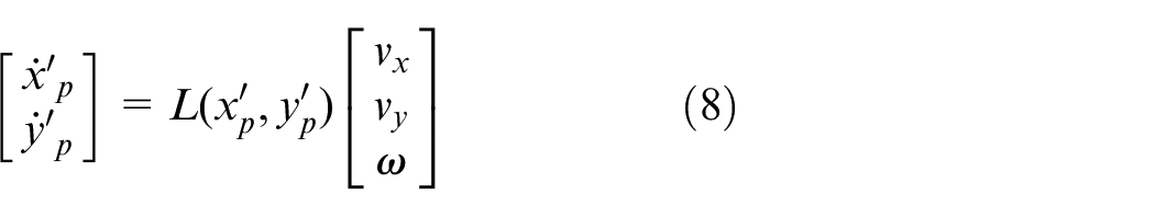
with
Define the posture variables (ρ1, ρ2) of the robot with its desired posture (ρ1*, ρ2*) as
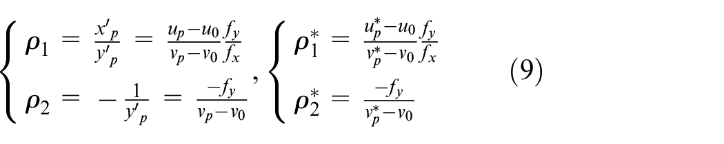
where (up*, vp*) are the desired coordinates of the point p in the image pixel coordinate frame. Then we have that

The error signals of the robot can be defined as
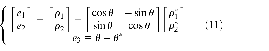
where θ* is the desired orientation of the robot and θ can be the estimated using the motion-estimated technique.
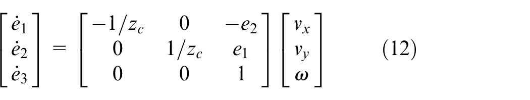
Taking the derivative of (11) and using (10), the visual servoing error system of the robot is described by
Kinematic model
This paper considers an omnidirectional WMR consisting of three eccentric steering wheels, whose top view is shown as Figure 2, where M is the mass center of the WMR, and A, B, and C are the fixed points of the three wheels relative to the robot body. These fixed points are located on the central axis of the vertical steering axis of each wheel when moving. The three wheels of the omnidirectional WMR are assumed to be exactly the same and the angles between MA, MB, and MC are identical to be 2π/3. In Figure 2, l is the distance from the center of the vertical axis of the wheel to M, α is the constant angle from the Xr axis of the robot coordinate system to MA, d, r, β, and φ are the eccentric distance, radius, turning angle, and rolling angle of the wheel, respectively. Note that the angles are positive when rotating counter-clockwise and the turning angle β is from MA to the axis of the wheel.
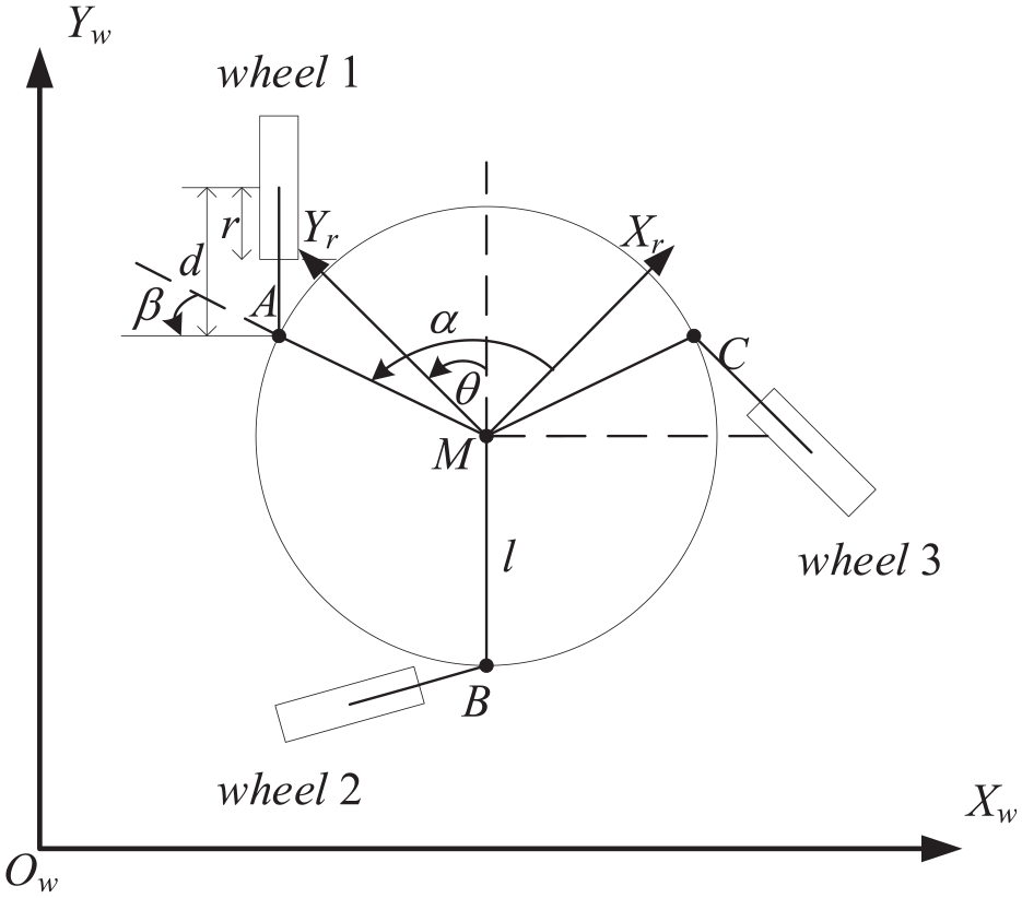
Top view of omnidirectional wheeled mobile robot.
The conversion relation between the rotation velocity
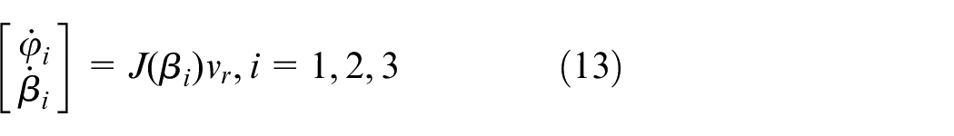
where
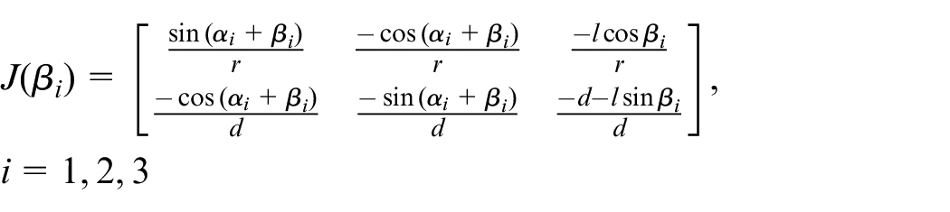
Combining (12), the visual servoing error system of the mobile robot with respect to the rotation velocity and deflection velocity of the wheel can be obtained, that is,

with the pseudoinverse matrix of J(β)
with J(β) = [J1 T (β1) J2 T (β2) J3 T (β3)] T . For implementation purpose, the model is discretized using Euler’s method with sampling time Ts > 0 as:

To ensure safety and effective execution of visual servoing systems, the robot should satisfy the velocity constraints and the visibility constraints for each sampling time k, that is,


where i = 1, 2, 3 and the subscript “min” and “max” indicate the lower and upper bounds of variables, respectively.
The objective of this paper is that the OWMR is driven to reach the feature point while meeting the constraints (16), and in the design process, the error e(k) and the velocity u(k) eventually approach zero.
Design of control strategy based on disturbance observer
In order to ensure the successful completion of the visual servoing task of omnidirectional mobile robot, the state constraints and output constraints of the visual system need to be considered. Therefore, a stability control law u(k) is designed for system (15) using the quasi-min-max MPC strategy. But in the actual system, the disturbance will disturb the rotation velocity and deflection velocity of the robot. By designing a nonlinear disturbance observer to estimate the external disturbance, and feedback compensation control input, the stabilization control of OWMR is finally realized. The visual servoing control block diagram of omnidirectional mobile robot based on disturbance observer is shown in Figure 3.
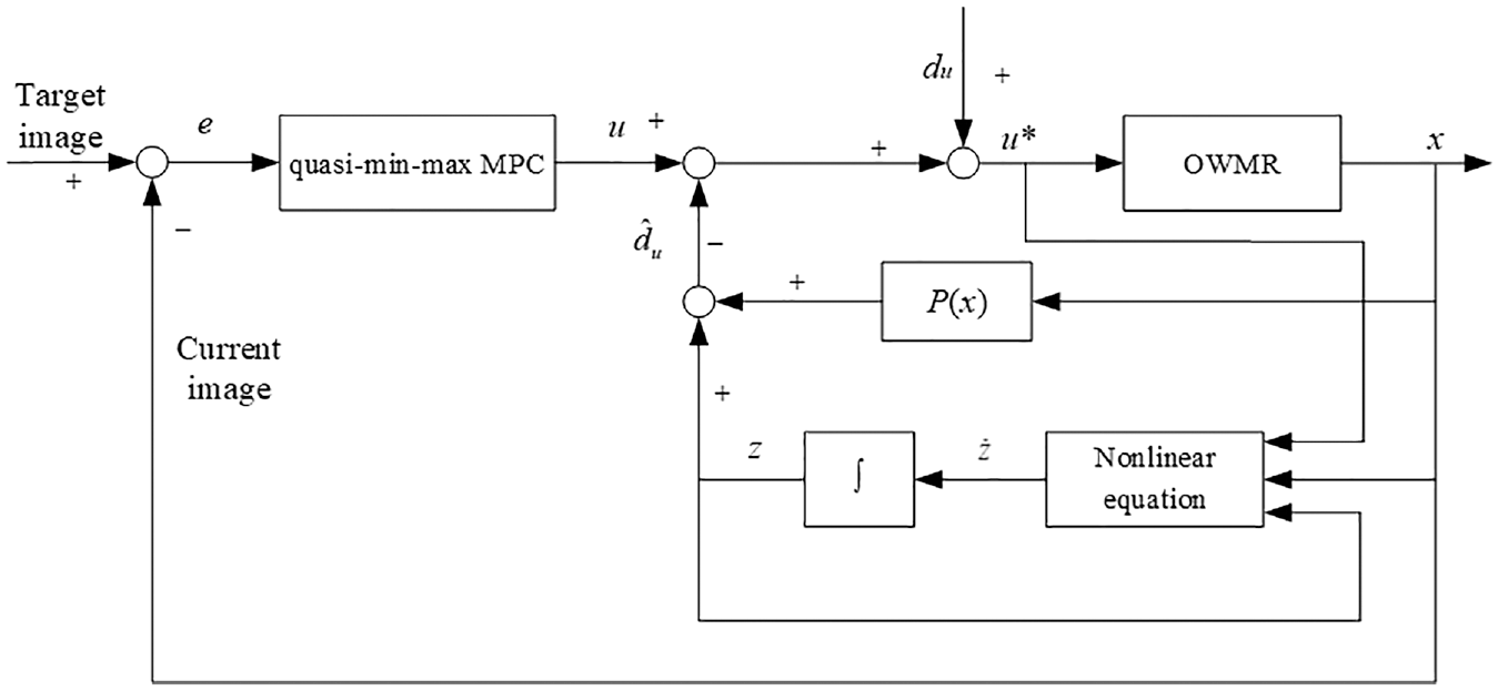
Visual servoing control block diagram of OWMR based on disturbance observer.
In the framework shown in the figure, the visual servoing task is divided into two sub-problems:
Without considering the existence of external interference, model mismatch, and parameter uncertainty in the model, the quasi-min-max MPC controller 5 is designed to obtain the control quantity based on the error state quantity at the current moment, which ensures the stabilization control of omnidirectional mobile robot, and satisfies the state constraint and input constraint control in the process of motion;
When there is lateral wind, complex ground environment and other conditions, that is, there is external disturbance, the disturbance is estimated and obtained by designing disturbance observer. The disturbance feedback is compensated into the control input channel to weaken or even eliminate the influence of the disturbance on the system.
Integrating the quasi-min-max MPC controller and the disturbance observer, the actual control quantity of the OWMR is
Design of controller based on quasi-min-max MPC
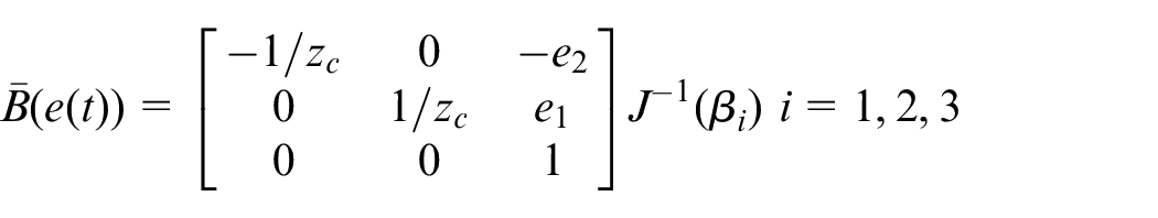
Consider the visual servoing error system (15) and let g(u) = J−1(β)u. Then the system (15) can be rewritten as:

where the matrix
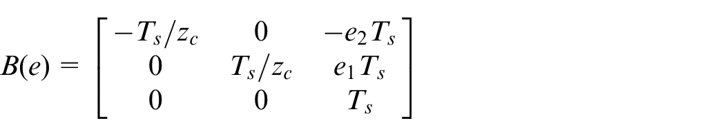
Notice that g(u) is a static nonlinear function. Hence, the system (17) is a multi-variable time-varying Hammerstein system which typically consists of a static nonlinear input followed by a linear dynamic model. 22 Let ū = g(u) and we have the linear time-varying dynamic model of (17)

It is further noted that B(e) is linear on the states e1 and e2. Then due to the constraints on those states, it is obtained from Baranyi 23 that B(e) can be covered by the convex polytope Ω, that is,

where C0 denotes convex hull and the matrices Bi = B(pi) for i = 1, …, 4 are the vertices with p1 = [e1min, e2min] T , p2 = [e1min, e2max] T , p3 = [e1max, e2min] T , and p4 = [e1max, e2max] T , respectively. Therefore, combining (19), the linear time-varying dynamic model (18) can be modeled as a polyhedral LPV system
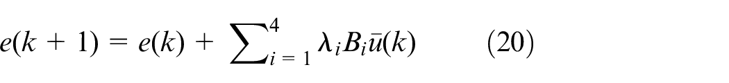
with the unknown parameters λi ≥ 0 satisfy that λ1 + λ2 + λ3 + λ4 = 1.
Consider the visual servoing system (20) and define the infinite horizon cost function
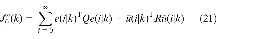
where •(i|k) is the value at k + i predicted at the current time k and weighted matrices Q > 0 and R > 0. In order to minimize the function (21), we consider the structure of (18) and use the system (20) to be the predicted model for (21). Notice that at each current time k, the matrix B(e(k)) can be determined via the measure of e(k) whilst B(e(k + i)) is not known but is covered by the convex polytope (19). Here the quasi-min-max MPC24–26 is adopted to achieve the control goal. Online solve the optimization problem to obtain the solution ū*(k).
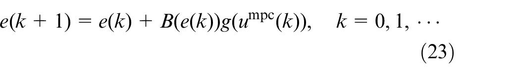
Then from the system (17) or (18), it is known that the corresponding optimal control u(k) = umpc(k) is uniquely determined by

which yields the closed-loop visual servoing system
Design of disturbance observer
Considering that it is very difficult to establish an accurate interference model or accurately measure the external interference through the sensor, a disturbance observer is used to estimate the disturbance.
According to the OWMR system model (4), the disturbance observer is designed as follows:
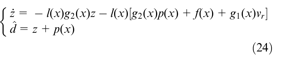
where z is the internal state of the nonlinear disturbance observer, p(x) is the function to be designed, L(x) is the gain of the observer, and

where
When the disturbance d is a slow-varying disturbance, the dynamic estimation error can be written as
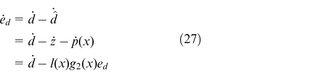
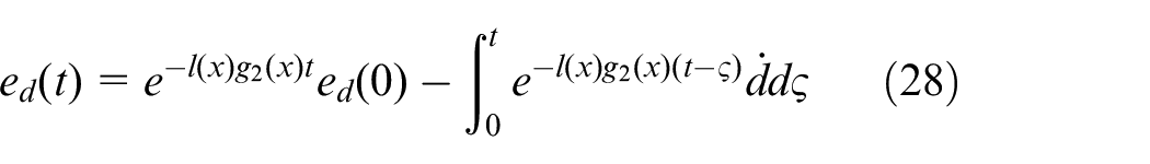
Differential equation solution of (27) can be obtained:
According to norm property, the following inequality can be obtained by (28)
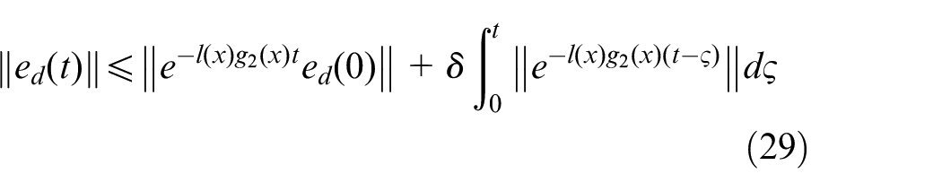
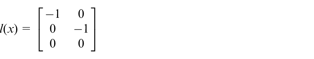
If l(x) satisfies that

Therefore, combining (29) with (30), it can be obtained
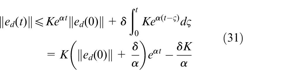
Therefore, by analyzing (31), it can be known that when
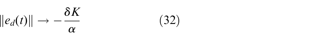
that is,
When the disturbance d is a constant bounded disturbance, the dynamic (27) of the estimation error can be written as

Since l(x) satisfies that
Through l(x), the linear function p(x) to be designed can be obtained according to (25). Then the disturbance observer (24) obtained is asymptotically stable.
Simulation
In this section, simulation experiments are implemented by using Matlab 2019a to verify the effectiveness of the method proposed in this paper, and LMI toolbox in the Matlab 2019a was used to solve the optimization problem. In this study, the physical parameters of the robot are selected as (l, d, r) = (0.8, 0.2, 0.1) m and (α1, α2, α3) = (π/3, π, −π/3) rad. The focal length of the camera mounted is f = 6 mm, the image resolution is 680 × 480 pixels, and the height zc from the origin of the camera coordinate system to the feature point P is 0.4 m. Moreover, the visual servoing system of the robot satisfies that −4.25 ≤ e1(k) ≤ 0, −12.5 ≤ e2(k) ≤ 0, and umax = −umin = [50 50 30 30 30] T . The sampling time Ts = 0.2 s, the diagonal matrices Q = diag{15, 1, 1}, R = diag{0.01, 0.01, 0.01, 0.5, 0.5, 0.5}. Let the initial steering angles of the three wheels of the robot be β1 = −3π/2, β2 = 3π/2, and β3 = 2π/3, respectively. Pick an initial pose (1.6, −5, 0) and the expected pose as (0, 0, 0).
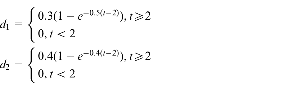
In other words, disturbances are added to the lateral and longitudinal velocities of the omnidirectional mobile robot to simulate external disturbances. The initial state of the disturbance observer (27) is
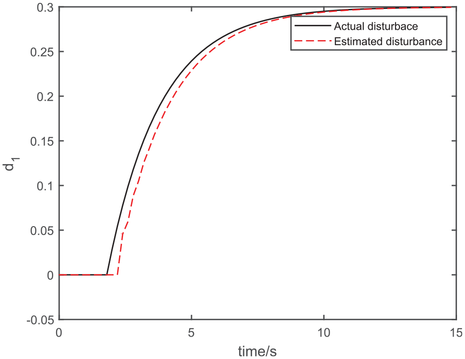
The disturbance d1.
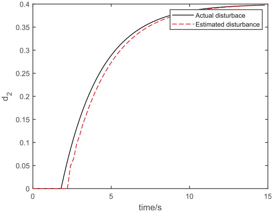
The disturbance d2.
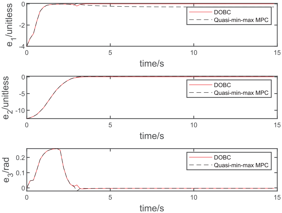
Error state.
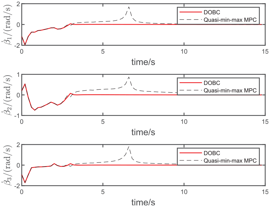
Wheel rotation velocity.
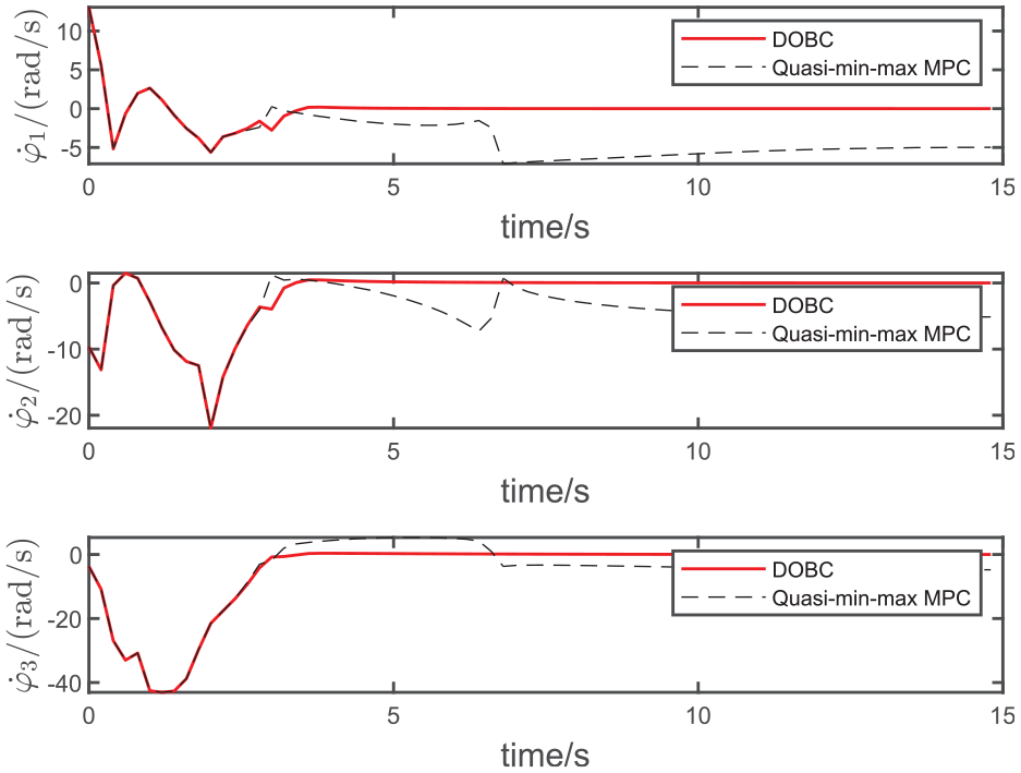
Wheel deflection velocity.
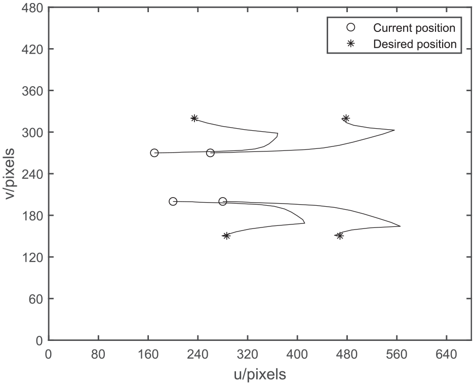
Trajectories of feature points in the image.
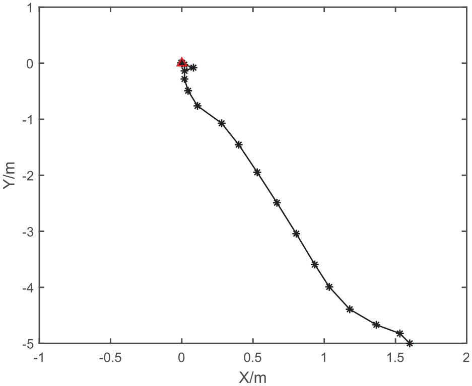
Trajectory of the OWMR on the X-Y plane.
As shown in Figure 6, the red solid line represents DOBC, and the dotted line represents quasi-min-max MPC. When the disturbance observer is not added, the dotted line error e1 has static error, so the omnidirectional mobile robot cannot reach the desired target point under large external interference and cannot complete the corresponding visual servoing task. When the disturbance observer is combined with the disturbance observer, the disturbance observer can compensate the external disturbance well, and then eliminate the influence of the external disturbance. The mobile robot can reach the target point, and complete the visual servoing task better finally.
As shown in Figures 7 and 8, the red solid line represents DOBC, and the dotted line represents quasi-min-max MPC. When no disturbance observer is added, the rotation velocity and deflection velocity of the wheels of OWMR are greatly affected by external disturbance, and the fluctuation changes are obvious. And the velocity of rotation is not stabilized to zero. In the control strategy based on disturbance observer, the rotation velocity and deflection velocity of the robot are less affected by external disturbance, and the final velocity tends to zero, that is, the OWMR reaches the target position.
It can be seen from Figures 9 and 10 that under the control strategy presented in this paper, the OWMR in the world coordinate plane and the feature points in the camera coordinate plane finally reach the desired positions. Figure 9 shows the trajectory of the robot from the initial posture to the desired posture, where the red triangle denotes the desired posture. The feasibility of the designed control strategy is proved. According to Figure 10, the feature points are always located within the visual field of the camera, which ensures the visual visibility of the mobile robot.
Conclusions
This study has proposed a disturbance observer based visual servoing stabilization predictive control procedure. Firstly, it studies the visual servoing error system to model of the omnidirectional mobile robot dynamics with the rotation velocity and deflection velocity of the eccentric direction wheel. On this basis, the asymptotic stability of the closed-loop visual servoing system without disturbance is guaranteed by combining the quasi-min-max MPC strategy. A nonlinear disturbance observer is designed to compensate the impact of external disturbances on the system. Simulation and comparison experiments verify the feasibility and effectiveness of the proposed strategy. The procedure has been tested by simulation and real experiments. In addition, new solutions to problems such as camera occlusion should be explored and evaluated in practical applications. For such control system design, a potential approach worthwhile being investigated is the model free sliding mode control. 27
Footnotes
Declaration of conflicting interests
The author(s) declared no potential conflicts of interest with respect to the research, authorship, and/or publication of this article.
Funding
The author(s) disclosed receipt of the following financial support for the research, authorship, and/or publication of this article: This work was supported by State Key Laboratory of Robotics and Systems (HIT) (SKLRS-2021-KF-11).