
Abstract
The problem of load nonlinearity is exposed as more and more load types are introduced into the radar power system. The nonlinear load is easy to produce large harmonic current, but at the same time it seriously threatens the normal and safe operation of other system equipment. How to design shunt active power filter (APF) to eliminate the harmonic effect of load and achieve stability as well reliability is a difficult problem for radar power system working at 115 V 400 Hz. This paper designs a hybrid optimization shunt active power filter, which can quickly detect and compensate harmonics, mainly includes fast harmonic detection module, space vector modulation module, composite control module and inverter module. Furthermore, the modeling and simulation of the hybrid optimization shunt APF are completed in MATLAB/Simulink software, and the parameters of radar power system are also redesigned. The simulation results suggest that, under heavy load conditions, the total harmonic distortion (THD) of the radar power side current is below 4.96%, and the short-period meaning filter only needs 0.0035 s to enter a new steady state in the face of load mutation. The APF designed in this paper can effectively suppress the harmonics in the radar power system, and greatly improve the dynamic performance while ensuring the steady-state performance of the system.
Introduction
To overcome some defects of traditional aircraft architecture and achieve high efficiency at low cost, the concepts of “all electric aircraft” and “multi-electric aircraft” are introduced.1–2 With the progress of “multi-electrification,” the power grid capacity of aircraft power system and the airborne electronic equipment are gradually increasing. Airborne radar is an important airborne electrical equipment in aircraft power supply system. It is directly powered by radar power supply system. Unlike the traditional large power grid system, it is a special 115 V/400 Hz microgrid operating independently. Unfortunately, most radar power supply systems include variable frequency loads represented by AC-AC frequency conversion devices and AC-DC-AC frequency conversion devices, rectifier loads represented by AC-DC rectifier devices and high-voltage pulse loads. Among them, the rectifier device is the main source of harmonic current generation. The common rectifier circuit in radar power supply system uses thyristor phase-controlled rectifier or diode uncontrolled rectifier. This typical nonlinear circuit means that there will be a large number of odd harmonics in the whole system.3–5
The narrow space in the airborne radar system between power supply and load magnifies the interference caused by harmonics to other electrical equipment, the stability and reliability of electrical equipment are damaged. There are two main methods to suppress harmonics. One method is to change the power electronic equipment itself, so that it does not produce harmonics, such as multi-pulse transformer rectifier,6–9 the multi-pulse transformer rectifier to provide full power supply to the load, its harsh conditions and large volume limit the application in radar power system. Another method is to install a harmonic compensation device, using the filter to compensate the harmonic,10–15 which is suitable for all kinds of harmonic sources, such as passive filter (PF) or active power filter (APF). PF relies too much on the fixed parameters of the power grid. However, the impedance and frequency of the power grid are constantly changing with the operation of the system and the switching of load carrying equipment. APF dynamically detects and compensates the harmonic current in the circuit, which is more suitable for the intelligent development of radar power supply system in the future.
Compared with the traditional 50 Hz inverter, the harmonic suppression of 400Hz intermediate frequency inverter is more difficult. Due to the limitation of switching devices, the switching frequency cannot be taken too high, which means the bandwidth of the controller is also limited. This thorny challenge not only leads to the large harmonic content in the output of intermediate frequency inverter, but also makes the traditional control methods difficult to ensure its steady-state and transient performance. Teng et al. 16 proposed a power factor correction strategy based on the PWM rectifier. This method does not use harmonic detection, but directly improves the rectifier, the control system included repetitive control with PI and feedforward control. The simulation results show that THD can be reduced to 2.92%. However, the simulation part only simulates 115 V 400 Hz system with third, fifth, and seventh harmonics, and lacks discussion of higher harmonics in the actual environment, so it has limited reference value. Hao et al. 17 conducted a detailed study on the frequency conversion system under intermediate frequency. Encouragingly, they used ip–iq method to detect harmonics and verified the anti-noise capability of ip–iq method in detailed. However, they ignored the delay problem caused by low-pass filter (LPF) in the algorithm, one solution is to use other improved filters instead of LPF to reduce the delay. Liu et al. 18 analyzed the dead-time effect and digital delay under intermediate frequency, they adopted LC filter with harmonic trap in series and proportional resonance controller with phase compensation in inverter. Harmonic trap is difficult to be used in radar power supply systems because of their large size. Li et al. 19 take 400 Hz intermediate frequency multiple inverter circuit as the research object and proposed a composite control strategy combining repetitive control and proportional resonant control. We find that repetitive control has excellent steady-state performance in intermediate frequency environment.
In fact, there are few research and designs for 400 Hz radar power supply system, so a complete system design with harmonic detection and control algorithm is particularly important. The prominent contributions of this article are as following.
A short-period mean filter (SMF) is proposed to replace the LPF based on ip–iq algorithm. In the system with higher fundamental frequency, the filter can significantly reduce the delay of traditional filter, so as to further improve the dynamic response performance of APF.
Compound control based on PI control and repetitive control parallel is proposed. Through MATLAB/Simulink simulation, it is verified that the compound control combined with improved fast harmonic detection greatly improves the dynamic performance, while taking into account the steady-state performance.
APF is designed for the radar power supply system under specific working environment, and the parameters of each link are given, which provides the theoretical basis and guidance for the practical application of APF in radar power supply system.
The rest of this paper is organized as follows: Section II introduces the structure and mathematical model of APF. In Section III, the overall model of the hybrid optimization active power filter in the software is described, and then the improved fast harmonic detection technology and composite control technology are analyzed theoretically. In Section IV, the steady-state performance and dynamic performance of the hybrid optimization active power filter are simulated, and the conclusion is given in Section V.
Principle of active power filter
Structure of APF
The schematic diagram of a typical APF is shown in Figure 1. The voltage at the power supply side is represented by Us and the current is represented by is. The three-phase uncontrolled rectifier circuit is a common nonlinear load in radar power system, it is the main culprit of harmonic generation. And to reduce harmonic interference and improve power quality, the APF is paralleled on the power side. The principle block diagram of the APF is as follows. At first, the harmonic current generated by nonlinear load is detected by harmonic detection algorithm. Then, the difference between the detected harmonics and the inverter harmonics generated are feed into the control module. Straight after, the control module output signal is modulated by space vector modulation to generate PWM signal. Finally, the inverter generates a current with the same harmonic current amplitude and opposite phase through PWM signal, which is injected into the power side to make the power side current close to the standard sine wave.
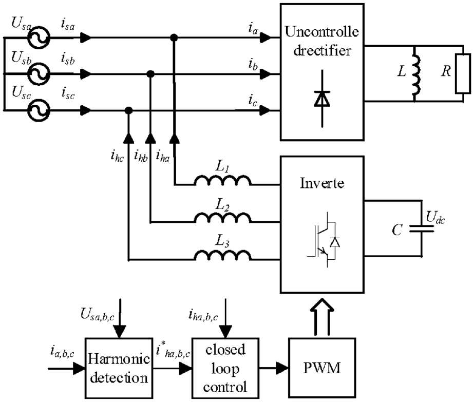
The principle block diagram of APF.
Mathematical model of APF
The system adopts three-phase three wire shunt active power filter structure, and each phase bridge arm has two IGBTs. For the convenience of modeling and analysis, ignoring the commutation process of power electronic devices and inductance saturation, Sa, Sb and Sc are used to represent the switch state of bridge arm, and the switch function is defined as follows:
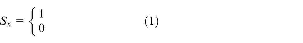
Where x can be any one of the three phases, Sx = 1 means that the upper arm of the phase is on and the lower arm is off, and Sx = 0 means that the upper arm is off and the lower arm is on. According to Kirchhoff’s law of current and voltage, the system state can be expressed as follows:
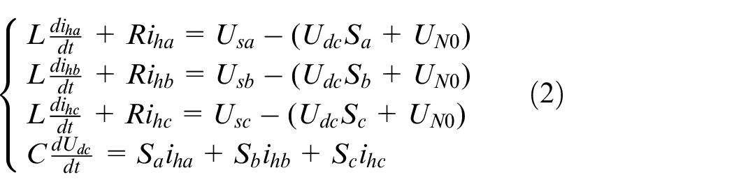
Where R is the parasitic resistance of inductance L, which can be ignored. Assuming that the system is three-phase balanced, there are:
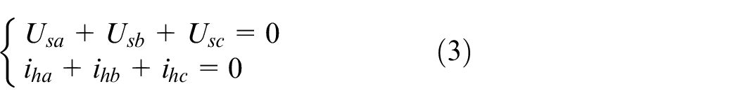
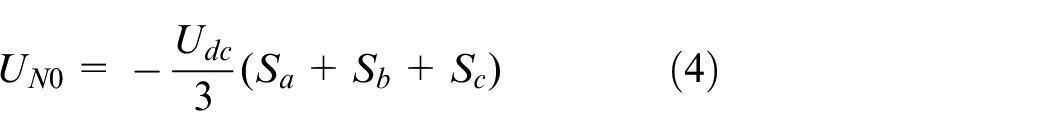
From this, UN0 can be further calculated as equation (4):
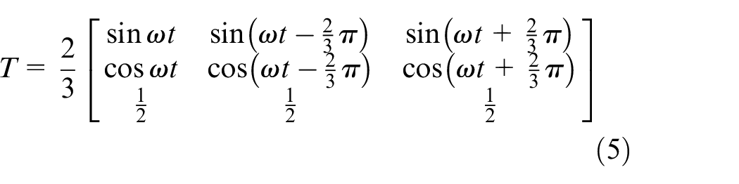
In order to realize decoupling control, the mathematical model of static abc three-phase system is transformed into dq0 rotating coordinate system. Supposed that the d-axis is set to lag phase a by 90°, meaning the q-axis and phase a are relatively homogeneous, then the transformation matrix is:
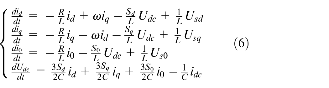
Therefore, the mathematical model of APF in dq0 rotating coordinate system can be expressed as follows:
Hybrid optimization active power filter
APF model
The experimental simulation of hybrid optimization APF is completed in Matlab/Simulink, and the specific model is shown in Figure 2. The model mainly includes six modules. The oscilloscope is used to check the voltage and current waveforms of each node. The nonlinear loads are used to generate harmonics. In order to observe the dynamic response performance of the system, the load mutation is designed in 0.15 s. The PWM signal is generated by space vector modulation. The inverter is used to generate the detected harmonics and inject them into the power supply side to cancel the harmonic current. The remaining two meticulous designed modules, harmonic detection module and the control module, are described in detail in the following two sections.
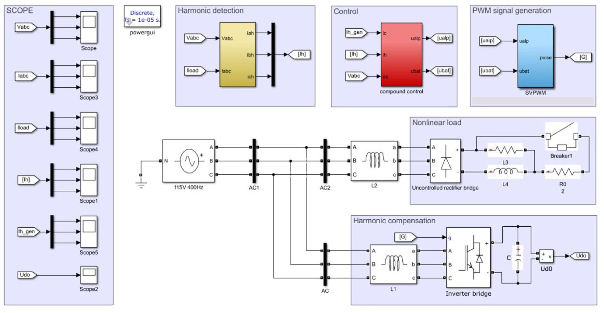
The hybrid optimization model of APF.
Improved fast harmonic detection method
The ip–iq method based on instantaneous reactive power uses phase-locked loop (PLL) to extract instantaneous voltage, which makes it insensitive to voltage distortion and has anti-interference ability. However, the LPF with high delay is used in this detection algorithm, in addition to that, the effect of reducing the delay by reducing the filter order is next to nothing. In contemplation of reducing delay in the detection process and improving the dynamic response speed, a short-period mean filter is proposed to replace the low-pass filter. The improved harmonic detection algorithm is shown in Figure 3, where T is the matrix transformation in formula (5).
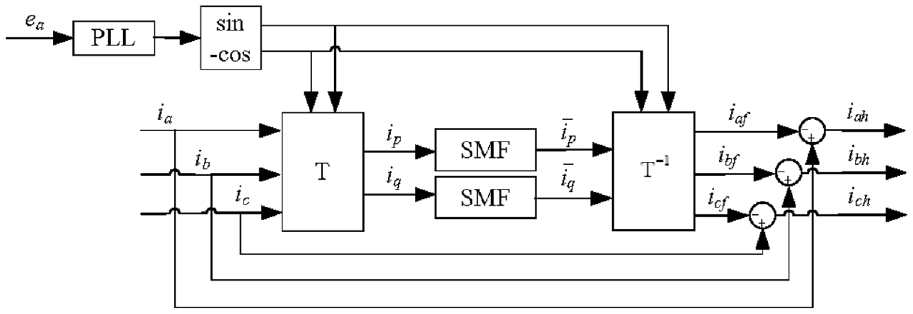
The principle block diagram of improved fast harmonic detection method.
Supposing that the three-phase voltage and current of the system are symmetrical, the PLL sets the voltage signal as a sine wave of unit amplitude, that is,
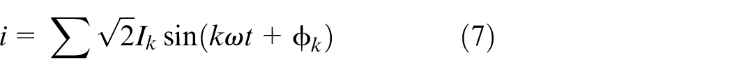
Wherein, k = 1, 6N ± 1, and N represents a positive integer, then instantaneous active current and reactive current can be calculated as follows:
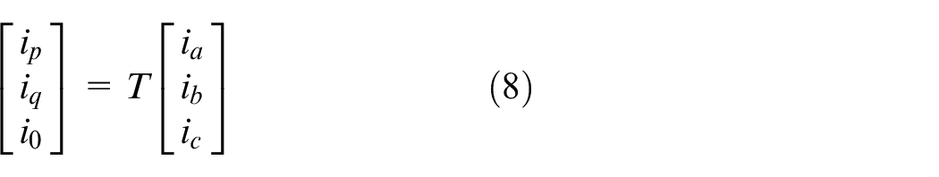
Take instantaneous active current as an example:
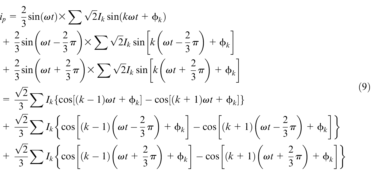
The current on the power side contains the fundamental frequency (k = 1) and the higher harmonic (k = 6N ± 1). Merge and reorganize the items after matrix calculation based on formula (5). The transformation process of formula (9) is shown in Figure 4, the fundamental frequency signal will become the DC component and the second harmonic, and the k = 6N ± 1 harmonic will be converted into the k–1 and k + 1 harmonic; at this time, the holistic radar power system only contains 6N–2, 6N, 6N + 2 harmonics.
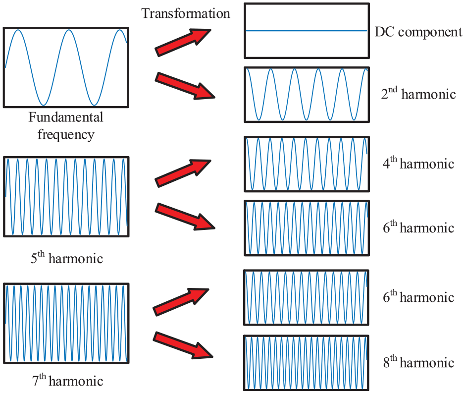
The current signal conversion process.
For the three-phase symmetric system, the 6N–2 harmonic contained in ip is
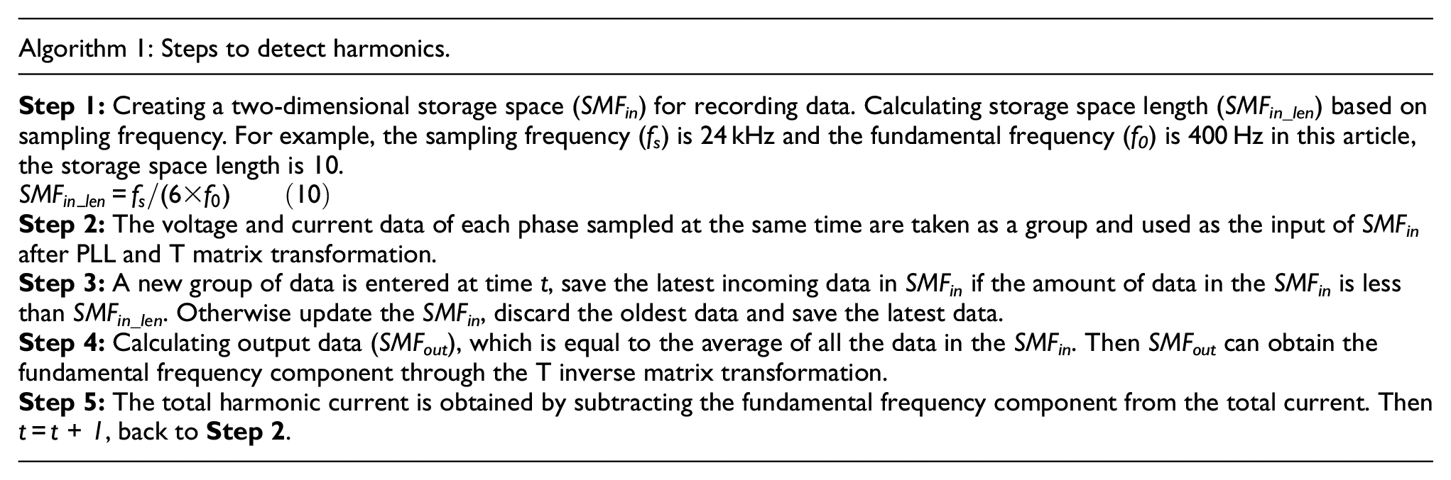
The proposed method theoretically has only 1/6 fundamental frequency period delay, that is, 4.167e−4 s, compared with the traditional LPF, this method greatly reduces latency, which means that high sampling frequencies (24 kHz) can bring better detection effect. It is important to note that the proposed detection method is lacks computational complexity since it can be done by simple addition and division. The algorithm in practical application is as shown in Algorithm 1.
Compound control strategy
To track the harmonic current quickly and accurately, the double loop control strategy of output voltage outer loop and inductor current inner loop is adopted. In the DC side of inverter, the capacitor is used as the voltage source.
In order to prevent the DC side capacitor fluctuation caused by APF loss, the voltage outer loop control is used to make the energy exchange between the DC side and AC side of the inverter, so that the active power is in dynamic balance. The principle of the voltage outer loop control is shown in Figure 5, that is, a link is added on the basis of Figure 3. Udc and Udc* are the reference value and the actual value of the capacitor voltage respectively, and then the difference is superimposed on the active component through PI control, which is the voltage outer loop control. The optimal PI control parameters are obtained through the training of quantum particle swarm optimization algorithm, Kp1 = 15, Ki1 = 195.
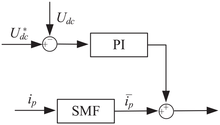
The voltage outer loop control schematic diagram of the PI control.
The basic idea of repetitive control improved from internal model is to accumulate the error cycle by cycle. When the output signal basically tracks the upper command signal, that is, when the error is basically zero, the output control quantity of repetitive controller can still meet the requirements. However, the repetitive control has a characteristic that one fundamental period delay to take effect, hence the transient performance of the repetitive control is poor. Considering the excellent transient performance of PI control, it is paralleled to repetitive control, which makes the system taking into account both steady and transient performance. PI control parameters in this link are Kp2 = 25, Ki2 = 243.
The structure of composite control is shown in Figure 6. N is the number of samples in a fundamental period, N = fs /f0, it is 60 in this article. Z−N is the period delay link, which applies the error detected in this period to the next period. The internal model coefficient Q(z) is expressed as a constant less than 1, which can ensure the stability of the system, specify Q(z) as 0.95. Kr is also to maintain the stability of the system, the smaller Kr means the higher stability and the slower convergence rate. After comprehensive trade-offs, set Kr to 0.9. The introduction of S(z) corrects the gain of the controlled object to 1 in low and medium frequency band, at the same time, the amplitude of the high frequency band will be further attenuate. Thus a second-order LPF with a cut-off frequency of 2400 Hz has been selected. The leading link Zk compensates for the phase lag in the low and medium frequency band, which is usually combined with the Z−N in the forward channel. According to the size of the synthetic phase shift of the controlled object and the second-order filter, the value of k is 2.
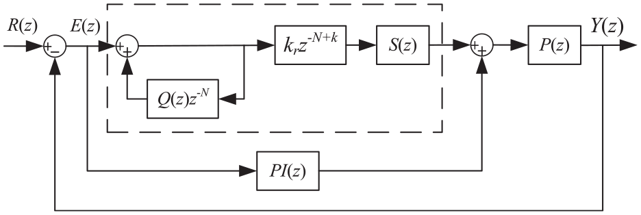
The current inner loop schematic diagram with the compound control.
Results and discussion of simulation experiments
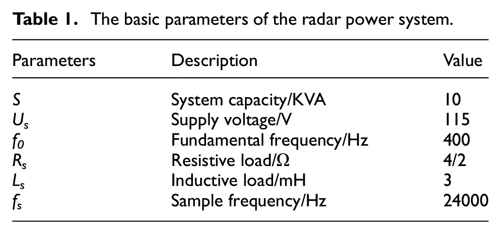
According to the model built in Figure 2, the simulation experiment is carried out. The key parameters of radar power supply system are given in Table 1.
The basic parameters of the radar power system.
Firstly, the DC side parameters of APF need to be configured. The SVPWM compensation current is expressed as follows:
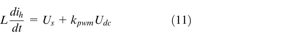
Among them, the kpwm values are ±1/3, ±2/3, 0, which represent the phase coefficients of SVPWM. The absolute value of the maximum phase voltage output from the AC side of the inverter needs to be greater than the amplitude of the phase voltage at the power side to meet the equation, that is, 1/3Udc > Us. The reference value of capacitor voltage at DC side of inverter can be calculated from the power supply voltage in Table 1. Setting the capacitor reference voltage at 500 V can keep a certain margin while considering the voltage resistance of switch. For the small volume of radar power system, 470 μF capacitor is used at DC side.
Improved fast harmonic detection simulation
The performance of traditional second-order Butterworth LPF and short-period mean filter in harmonic detection is compared. The load is changed from 4 to 2 Ω in 0.15 s to simulate the load mutation. The dynamic response performance of the filter is observed. The performance of the two filters is shown in Figure 7.
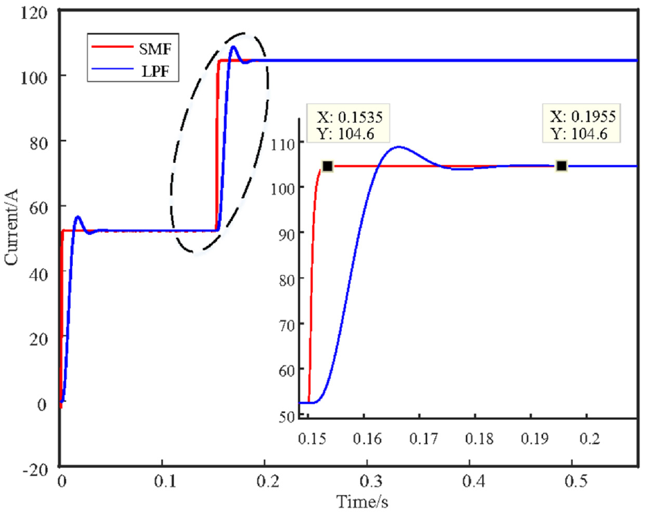
The comparison of dynamic response performance of two filters.
It can be seen from Figure 7 that the two filters can extract the same DC component when they are stable. After 0.15 s load mutation, the LPF reaches the steady state in 0.1955s and the delay reaches 0.0455 s. The frequency response curve of the LPF gradually drops to zero in the stopband, so it has a period of oscillation before entering the new steady state, the errors existing in the detection link are bound to affect the dynamic response performance of APF. In contrast, the customized SMF benefits from system specificity only needs 0.0035 s to re-enter the stable state. It has a certain gap with the 1/6 fundamental period delay of theoretical analysis, we believe that the main reason for this situation is that the system also has a transient process during load switching, but it still avoids oscillations and shortens the delay time.
Simulation of APF
Taking phase A for example, when the radar power supply is directly connected to the nonlinear load, the current waveform at the power supply side is shown in Figure 8, and the result of Fourier analysis is shown in Figure 9.
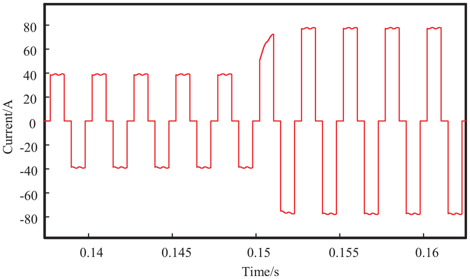
The current waveform of power supply side before filtering.
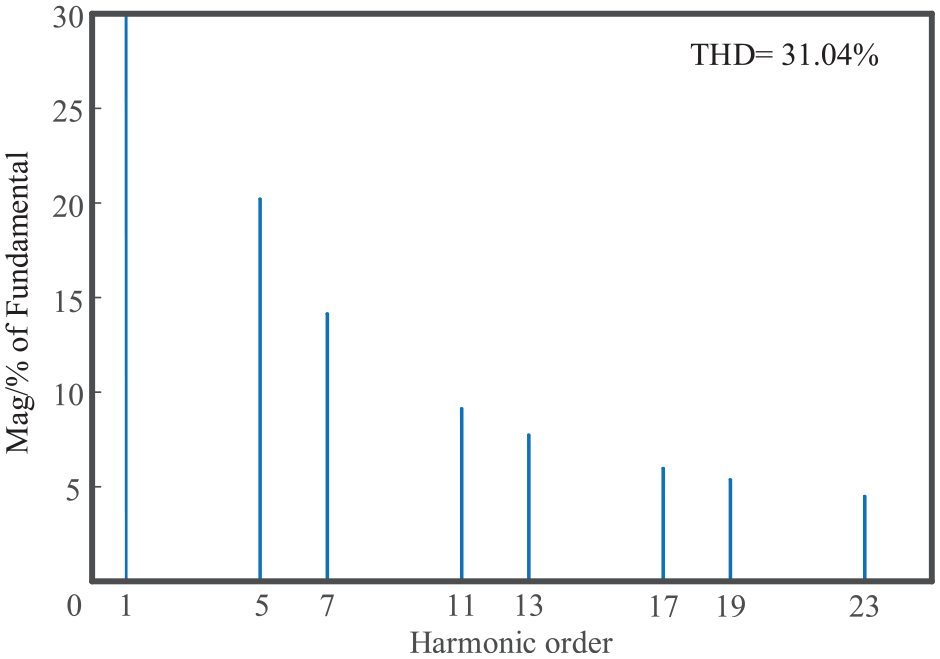
The current spectrum of power supply side before filtering.
The calculation formula of THD is as follows:

Where Q represents the total effective value, Q1 is the fundamental effective value, and the THD experimental value is close to the theoretical calculation value.
In this paper, the traditional APF based on ip–iq method and PI control is taken as the traditional scheme, and the filtering effect is compared with the proposed joint optimization active power filter. The results are shown in Figure 10, in which the joint optimization method enters a new steady state in one cycle, the traditional method can enter the new steady state only after several cycles of oscillation, revealing the APF with joint optimization can enter the steady state faster. This experimental result is consistent with our analysis conclusion in Figure 7. The oscillation in the traditional ip–iq detection algorithm will directly lead to the output oscillation of APF, and the overall filtering effect of APF will be further improved after the oscillation is eliminated from the detection algorithm. In addition, the method using only PI control has burrs after filtering, while the filtering result is very smooth after adding repetitive control.
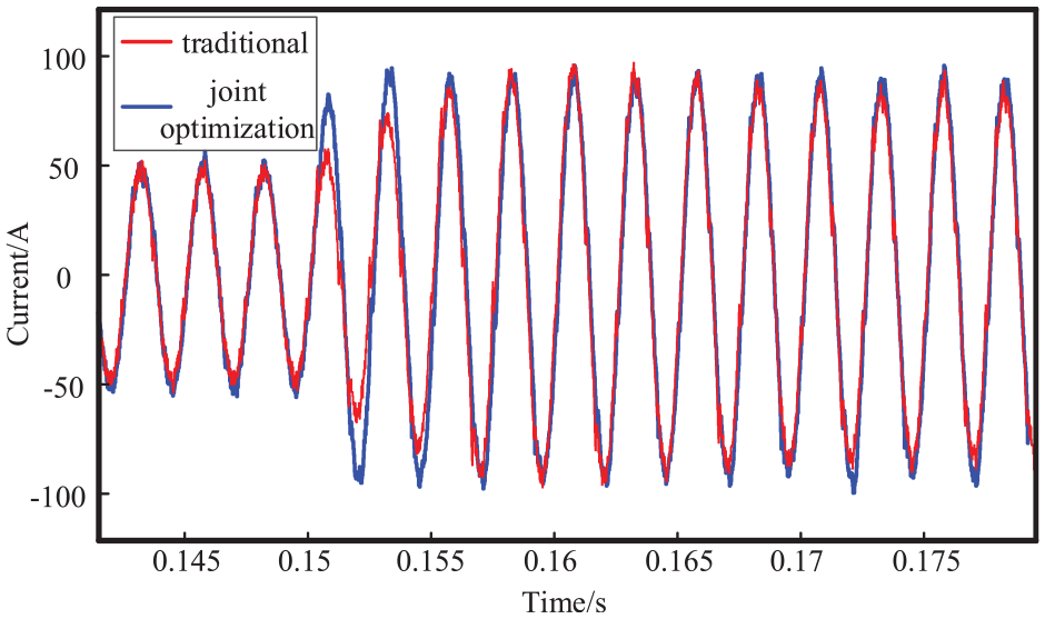
Comparison of power side current waveforms after filtering of two schemes.
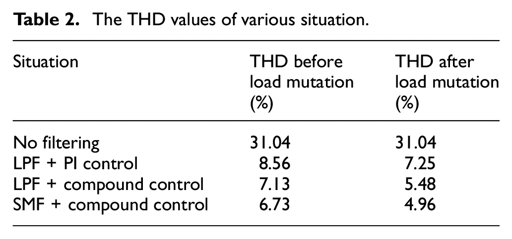
The filtering effects of the combination of three different detection methods and control methods are listed in Table 2. For the convenience of representation, the traditional ip–iq detection method is denoted as LPF and the improved fast harmonic detection method proposed in this paper is denoted as SMF. Through the comparison of the first two groups of experiments, it can be concluded that compound control has better steady-state performance, which makes up for the poor steady-state performance of PI control. The latter two groups of experiments reflect the superiority of the proposed detection algorithm, which can detect harmonics more accurately, and further reducing the THD content. Through the comparison of different working conditions, it can be seen that THD under heavy load condition is smaller than light load condition, which is the result of optimization according to heavy load during design.
The THD values of various situation.
Further analyzing the filtering effect of the jointly optimized APF, Figure 11 shows the spectrum after filtering. The existence of the inverter in the APF circuit leads to the introduction of low order harmonics in the power supply side. However, the content of this part is low, which is less than 0.4%, and has little impact on the radar power supply system. Moreover, the previously existing large harmonic current, such as the fifth harmonic current, is reduced from 20.08% to 1.19% after filtering, and other sub-harmonics are also greatly reduced. Figure 12 shows the time-frequency diagram obtained by wavelet analysis. It can be clearly seen that the frequency component of power side current after filtering is concentrated at 400 Hz, and the 0.15 s load mutation does not have a great impact on the system. On the whole, the filtering effect is stable. Figure 13 compares the detected harmonics with the generated harmonics. The trend of the two curves is almost identical, shows that the inverter controlled by parallel PI with repetitive control perfectly tracks the output of improved fast harmonic detection, thus obtaining APF with good dynamic and steady performance.
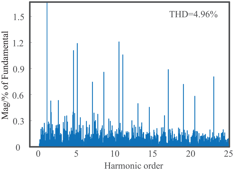
The power side current spectrum of hybrid optimized APF.
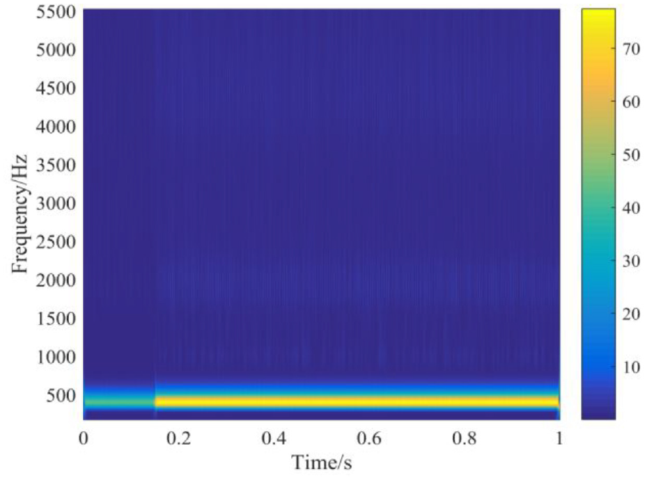
The power side current time-frequency diagram of hybrid optimized APF.
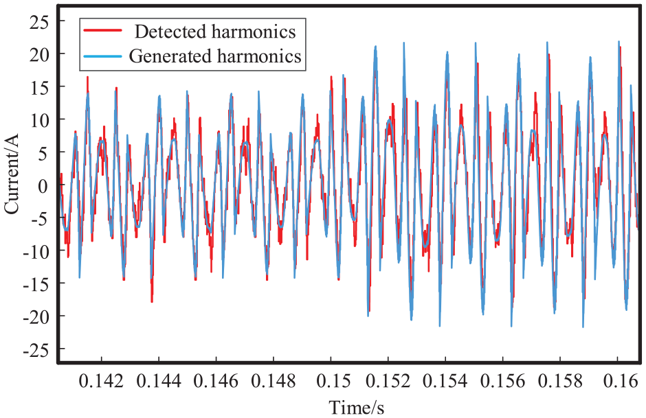
Comparison of current waveforms for harmonic detection and compensation.
Conclusion
Aiming at the radar power system with 115 V 400 Hz, this paper designs a hybrid optimization APF to suppress the harmonic current in radar power system. The optimized APF uses several key techniques to improve the performance of harmonic suppression. The improved short period rapid harmonic detection uses 1/6 fundamental frequency periods for integration to reduce the delay. At the same time, PI control is paralleled with repetitive control to form a compound control, which is used to coordinate the rapid harmonic detection to ensure the stability and improve the dynamic performance. Simulation section specially sets the load mutation situation to observe the dynamic performance of the system, the results show that the optimized APF can quickly move to a new steady-state and has a smaller THD value in steady-state operation. Inspired by literature,10,20–22 in the next step, we will regard the sampled data as time series, use recurrent neural network (such as echo state network) to predict it, and try to obtain preferably filtering performance in combination with dead-beat control. At the same time, we will make a prototype to further implement the proposed algorithm.
Footnotes
Declaration of conflicting interests
The author(s) declared no potential conflicts of interest with respect to the research, authorship, and/or publication of this article.
Funding
The author(s) disclosed receipt of the following financial support for the research, authorship, and/or publication of this article: This work was supported in part by the Fundamental Research Funds for the Central Universities of China (No.PA2020GDKC0019).