
Abstract
The occlusion of shade leads to the intermittent reception of satellite signals, which subsequently results in a decline of the positioning accuracy of Global Navigation Satellite System (GNSS). In order to improve the accuracy of positioning and ensure the continuity of navigation results in weak signal environment, a cubature Kalman Filter (CKF)-based micro-electro mechanical-system (MEMS) grade inertial navigation system (INS) assisted GNSS vector tracking (VT) loop is proposed in this paper. Combining effective GNSS measurements and INS information, attitude, velocity, and position results are predicted by CKF, and the pseudo-range results from navigation filter are fed back into the VT loop. The field tests show that the proposed CKF-based MEMS-INS assisted GNSS VT loop can run continuously and stably in weak signal environment with higher navigation accuracy.
Keywords
Introduction
With the development of unmanned and autonomous technology, credible location and positioning information are becoming more and more important and critical.1,2 The Global Navigation Satellite System (GNSS) receiver has become one of the most popular navigation devices for providing precise position information. The GNSS receiver design mainly includes three processing steps: acquisition, tracking, and navigation solution. The carrier phase/frequency and code phase are finely estimated in the tracking link and send to navigation link, the navigation filter combines the ephemeris information to calculate the position, velocity, and time information. The traditional GNSS scalar (CT) tracking loop includes carrier loop and code loop, where the code loop is usually implemented by delay-locked loop (DLL), and the carrier loop includes phase-locked loop (PLL) and frequency-locked loop (FLL). All tracking loops are tracking different satellite signal independently and there is no interaction between channels. 3 In order to improve tracking stability, the more universally adaptive vector tracking (VT) loop was proposed. 4 Unlike the traditional CT algorithm, the VT loop can combine with navigation results to assist the tracking link so that the receiver obtains enough total signal power to successfully track the signal.5,6
GNSS signal power is significantly attenuated in degraded environments such as indoors, tall buildings, leafy trees, the carrier-to-noise ratio satellite signal is reduced, a carrier-to-noise ratio less than 28 dB/Hz is regarded as weak signal generally. 7 If there is a low carrier-to-noise ratio signal, the VT loop is susceptible because each satellite channel is dependent. The combination of VT scheme and inertial navigation system (INS) is a new approach to construct a reliable navigation system. Because of its better stability and reliability, GNSS/INS integrated navigation system has been widely recognized as a promising alternative to stand-alone GNSS for navigation in weak signal environment.8,9 Due to the high price of high precision gyros like laser gyro and optic gyro, micro-electro mechanical-system (MEMS)-grade accelerometers and gyroscopes are being used widely as low-cost Inertial Measurement Unit (IMU) sensors. Whereas, it reduces the accuracy of the GNSS/INS navigation system. It is keenly to achieve the same level of accuracy through advanced data fusion technology.10–14
Kalman filter (KF) is used in a wide range of applications including communication, navigation, measurement, and control.15–17 For navigation field, KF is not only used in optimizing the tracking loop but also acting as a fusion filter for GNSS and INS. The classical GNSS/INS data fusion uses the error propagation theory of the INS as the basis for the KF estimation algorithm. The data fusion of GNSS/INS is actually a non-linear filtering problem, INS model will introduce linearization errors in the KF estimation. 18 In order to reduce linearization errors, advanced data fusion methods have been extensively investigated. Various non-linear filtering techniques, such as the extended Kalman Filter (EKF), the unmarked Kalman Filter (UKF), and the cubature Kalman Filter (CKF) are used in the field of navigation.19–21 The EKF approximates the non-linear model by a Taylor series expansion, while it’s computationally intensive due to the calculation of the Jacobi matrix and poor estimation accuracy by ignoring higher order terms. For GNSS/INS, EKF is not effective in event of weak observability and large initial yaw error. 22 The UKF is comparable to EKF in terms of computation complexity and has higher estimation accuracy than EKF, but it’s less effective for high-dimensional filtering. Because the dimension of GNSS/INS integrated navigation is 15 or higher, CKF has higher accuracy and is more stable than UKF in navigation field. 23 However, researchers have only applied the CKF to GNSS/INS integrated system and have not combined the CKF navigation results with GNSS loop tracking.
To improve the accuracy of positioning and ensure the continuity of navigation results in weak signal environment, a CKF-based MEMS-INS assisted GNSS VT loop is proposed in this paper. Attitude, velocity and position results are predicted by CKF combining effective GNSS measurements and INS information, and pseudo-range and pseudo-range rate are fed back into the tracking loop. INS can navigate independently when GNSS satellites are less than four, when GNSS signals return to normal, GNSS/INS integration system would work properly and correct INS errors. The proposed architecture is assessed by field tests, and results demonstrate that the proposed algorithm can run continuously and stably in a weak signal environment, and the navigation accuracy is higher than traditional GNSS VT algorithm.
The rest of this paper consists of four sections. Section 2 introduces traditional VT structure; Section 3 explains the proposed CKF-based MEMS-INS assisted GNSS VT loop; Section 4 analyzes the test results in; and Section 5 draws the conclusion.
Traditional VT structure
The traditional VT Loop is shown in Figure 1. The detailed implementation uses for reference the software defined receiver (SDR) based on VT was proposed in a previous study. 24 The digital intermediate frequency (IF) signal of different channel is mixed, correlated, integrated, and dumped, the output results are then sent to loop discriminator to obtain the phase error of the carrier and code replicas. The carrier phase/frequency and code phase errors are linearly transformed to pseudo-range rate error and pseudo-range error, which are sent to the KF for achieving position, velocity, and time information. Combining with the KF positioning results and ephemeris data, the predicted pseudo-range is used to control code numerically controlled oscillator (NCO) and fed back to each tracking loop. To do this, satellite ephemeris data must be known in advance. In this paper, the ephemeris data is obtained by conventional tracking first.
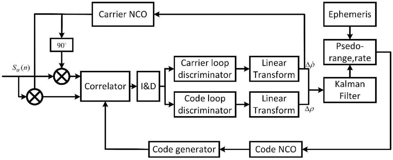
The block schematic diagram of traditional VT structure.
The pseudo-range error
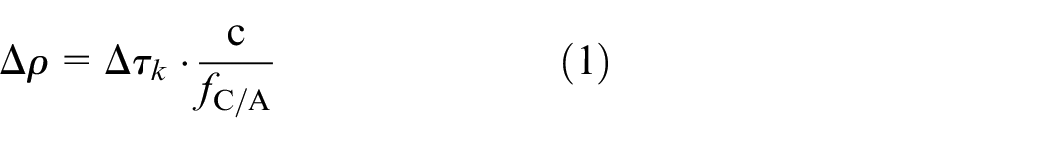
where
The code frequency
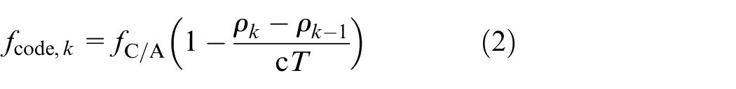
where
The pseudo-range
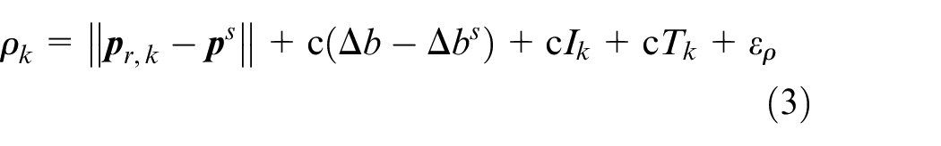
where
The proposed CKF-based MEMS-INS assisted GNSS VT loop
As is shown in Figure 2, the proposed CKF-based MEMS-INS assisted GNSS VT loop includes GNSS, the INS, and the integration navigation filter. On the basis of CKF, GNSS measurement and INS information are integrated to predict attitude, velocity, and position. INS can navigate independently when GNSS signals are invalid, GNSS/INS integration system would work properly and correct INS errors when GNSS signals return to normal. Note that the GNSS navigation in Figure 2 represents the GNSS navigation results, including position, velocity, and time information.
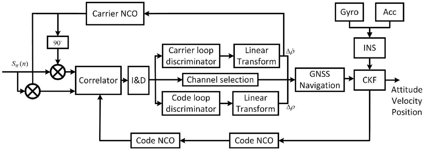
The block schematic diagram of proposed CKF-based MEMS-INS assisted GNSS VT loop.
When the carrier to noise ratio is lower than the predetermined threshold, the GNSS fails and tracking loop may loss of locking. INS operates independently when GNSS is invalid. The carrier-to-noise ratio is calculated as
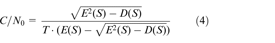
where
GNSS/INS with classical KF
Traditional GNSS/INS combination tool is KF, including state model and measurement model.
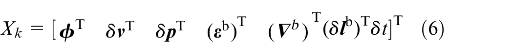
The state model of KF 25 is

where
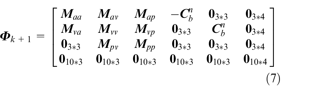
where
The measurement model of KF is
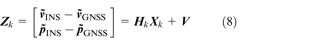
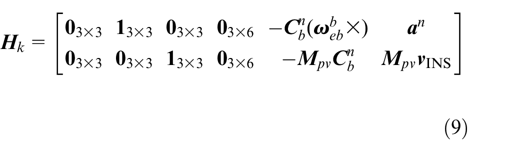
where
GNSS/INS with CKF
Similar to classical KF, the CKF consists of two parts: prediction and correction. The algorithm structure of CKF is shown in Figure 3.
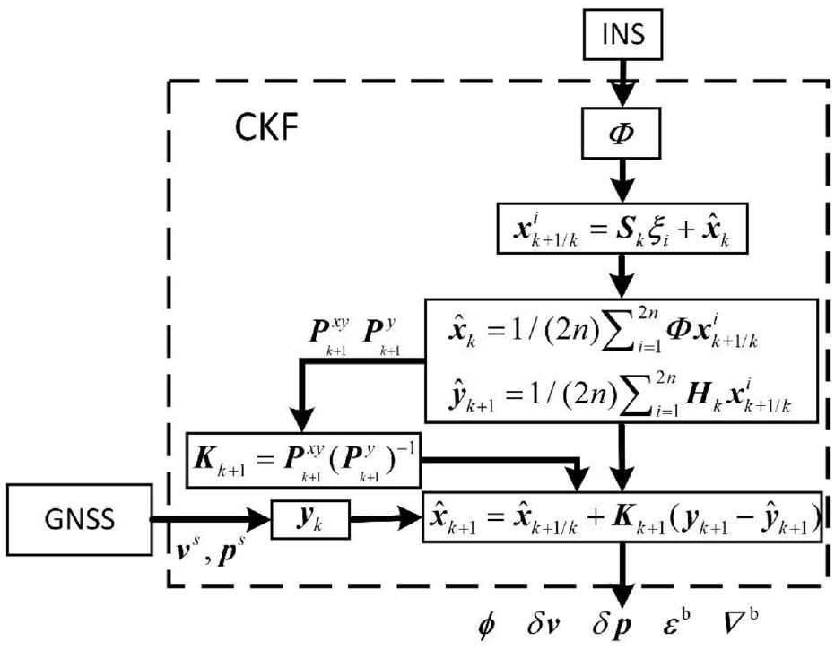
Algorithm structure of CKF.
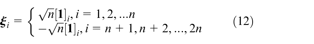
Cubature point calculation
By the spherical radial criterion, we can find that 26


where
where
Update of CKF
One-step prediction of the state mean value
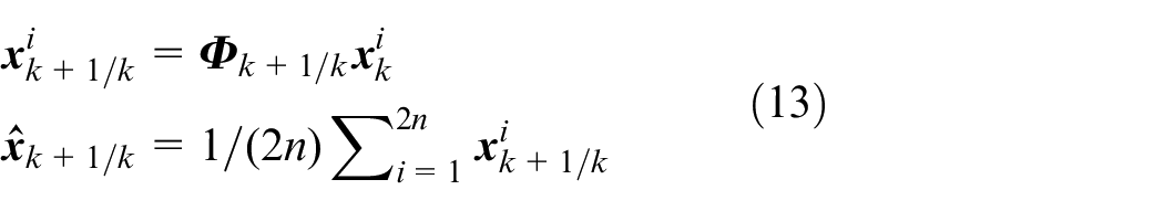
One-step prediction of the variance of state values
where
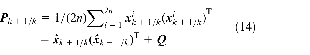
The mean value of the one-step predictive measure is
The variance of the one-step prediction measure is
where
The covariance between the one-step predicted state value and the one-step predicted quantitative value is
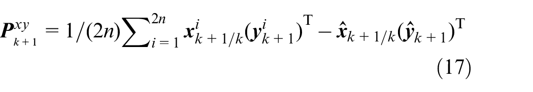
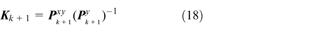
The cubature Kalman gain is
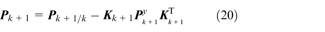
The posterior mean and posterior variance of the target state are

Results and discussions
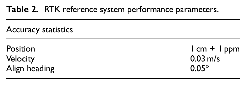
An electric vehicle is chosen to implement and test the algorithm. The GNSS/MEMS-INS system integrated a low-cost STIM-300 MEMS-based IMU with a GNSS IF signal collector. The GPS L1 signal is collected by the GNSS IF signal collector with IF is 3.996 MHz and the sampling frequency is 16.369 MHz. The noise parameters of STIM-300 are shown in Table 1. In order to get accurate reference information, a real-time kinematic (RTK) equipment was also mounted on the electric vehicle during the field test. The RTK equipment consists of positioning and orientation board (OEM617) developed by Beijing Beidou star navigation Co., Ltd., a GNSS base station, and radio links for data communication. The reference system performance parameters are shown in Table 2. The experimental setup is shown in Figure 4.
Noise parameters of STIM-300.
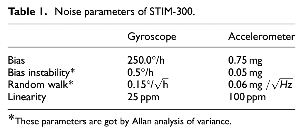
These parameters are got by Allan analysis of variance.
RTK reference system performance parameters.
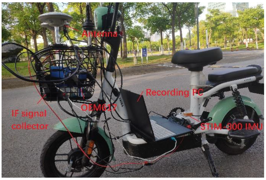
Experimental setup.
The environment of field test is shown in Figure 5. The field test was conducted in road with shade of trees of Shanghai Maritime University. The duration of the test was 110 s, with the electric vehicle first standing still in an open area for 30 s, passing through a shaded area and finally standing still in an open area. The initial position is (30.8743°N, 121.8994°E, 6.1396 m). The path of shade of trees was a straight line.

Environment of field test.
Five different tracking loops are compared and analyzed in this test, including traditional CT GNSS, traditional VT GNSS, GNSS/INS based KF, GNSS/INS based UKF, and the proposed GNSS/INS based CKF.
Five GPS satellites (PRN 2, 6, 12, 19, 20) are visible in initial moment. The loop state comparisons (carrier frequency and code frequency) of PRN 19 are shown in Figure 6, including traditional CT GNSS, traditional VT GNSS, and the proposed MEMS-INS assisted GNSS VT loop, referred to as GNSS/INS.
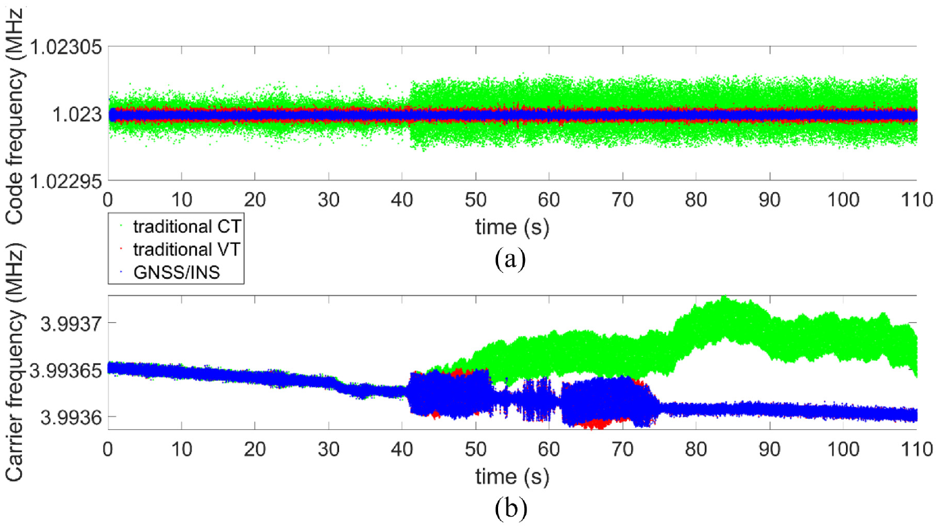
The code frequency and carrier frequency of PRN 19: (a) code frequency of PRN 19 and (b) carrier frequency of PRN 19.
In Figure 6(a), the code frequency of traditional CT changes greatly, especially after entering the shade of trees, the code frequency change increased significantly and the code loop is completely out of lock. The code frequency changes of latter two methods are little, and the tracking result of GNSS/INS is slightly better than traditional VT, because the code frequency fed by pseudo-range from navigation result has higher tracking accuracy. In Figure 6(b), the carrier frequency change is similar as code frequency, the carrier frequency waves significantly under the shade of trees. With the exception of the traditional CT method which is completely out of lock, the other two methods are only occasionally out of lock and do not affect signal re-locking. The maximum Doppler shifts of all five GPS satellites are shown in Table 3.
Maximum Doppler shifts of all satellites.
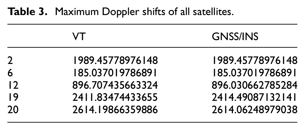
Figure 7 exhibits the number of effective channels in the MEMS-INS assisted GNSS VT loop. The number of effective channels is significantly reduced when passing through the shade of trees. INS operates independently when the number of effective GNSS channels is less than four.
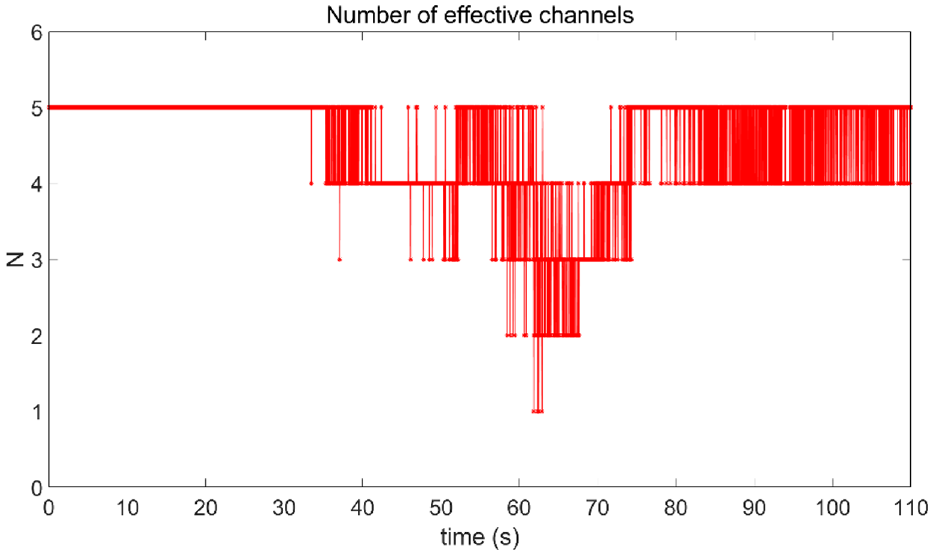
The effective channels number in field test.
The trajectory of field test approximates a straight line in Figure 8. The distribution of positioning result of the traditional VT method can basically show the movement trajectory, but the navigation results in the shaded of trees are still scattered. The navigation results of GNSS/INS can correctly indicate the movement trajectory. Compared to the reference trajectory represented by the solid black line, the positioning result of proposed GNSS/INS based CKF algorithm is much closer to the real trajectory with higher accuracy. The position errors of different navigation filter (KF, UKF, and CKF) are shown in Figure 9.
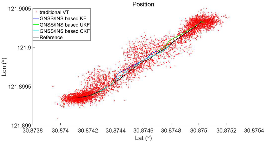
Position results of different navigation systems.
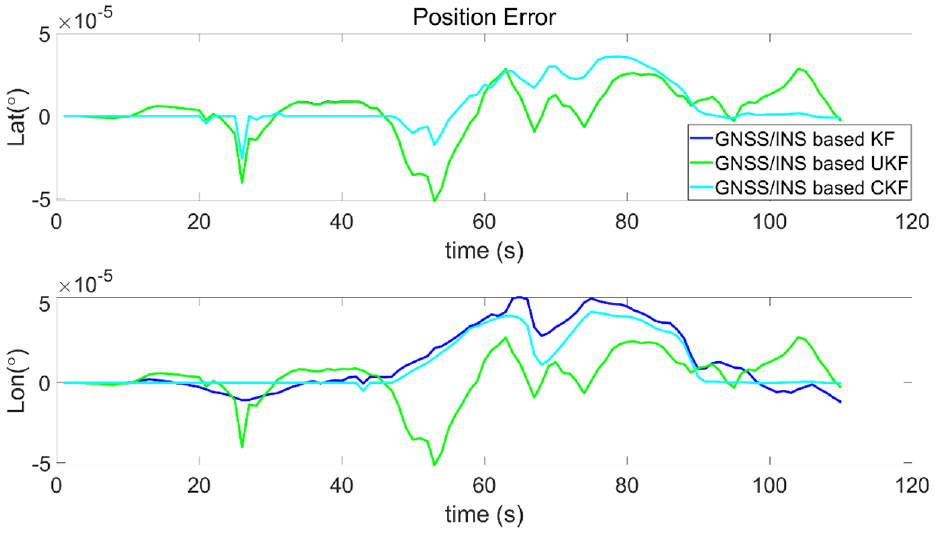
Position error of different navigation filter.
The computational cost of the three filters is compared. The navigation results are obtained in MATLAB R2018b software with a computer of Intel(R) Core(TM) i5-10210U CPU and 64-bit operating system. The calculation times for the three methods (GNSS/INS based KF, GNSS/INS based UKF, and the proposed GNSS/INS based CKF) are 309.691, 666.336,and 325.114 s respectively. Hence, compared with KF, the additional computational load of CKF is not heavy.
The precision of position solution is necessary to assess the reliability of service and the precision parameters of navigation system. 27 The Root Mean Squared Error (RMSE) of position are given in Table 4, and it is defined by

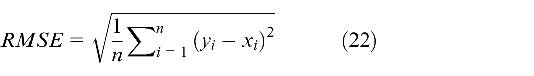
where
RMSE of position for different algorithm.
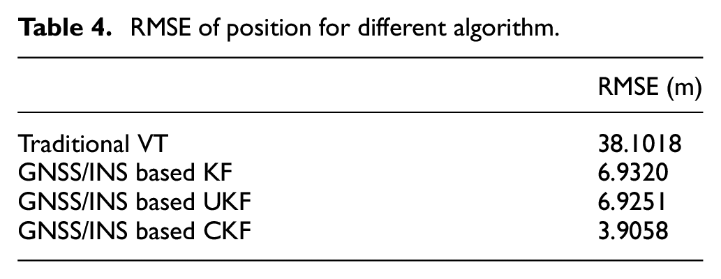
As the RMSE of position for different algorithm from Table 4, it can be seen that the CKF-based MEMS-INS assisted GNSS VT Loop has the highest positioning accuracy compared to other navigation results.
Conclusions
A CKF-based MEMS-INS assisted GNSS Vector tracking Loop is proposed in this paper. The proposed algorithm is adopted to address the accuracy loss caused by interrupted GNSS signal. For tracking processing step, the code frequency is predicted by new pseudo-range from navigation filter in code tracking loop. For navigation processing step, the effective GNSS measurements corrected for MEMS-INS error by CKF. Field experiments demonstrate the effectiveness and superiority of the algorithm. Experimental results show that the proposed algorithm can run continuously and stably in weak signal environment with higher navigation accuracy.
Footnotes
Declaration of conflicting interests
The author(s) declared no potential conflicts of interest with respect to the research, authorship, and/or publication of this article.
Funding
The author(s) disclosed receipt of the following financial support for the research, authorship, and/or publication of this article: This work was funded by the National Key Research and Development Program of China (Grant No. 2021YFC2801003, 2021YFC2801004), the National Natural Science Foundation of China (52071199), and the Shanghai Natural Science Foundation (19ZR1422800).