
Abstract
Line-structured laser sensors used in gear measuring provide a new way to acquire the perfect 3-D information of the complicated tooth flank with modification. This method leads to a series of problems, such as incident light occlusion, multiple reflection, system calibration and so on. The incident light occlusion poses severe problem on the integrity of the gear flank data acquired by the line-structured laser sensors. To understand the influence of the incident light occlusion during the cylindrical gear measuring and improve the efficiency of the measurement, this article analyzes this problem in depth. According to the position relation between the line-structure laser sensor and the gear, the projection theory is used to illustrate the incident light occlusion process between adjacent teeth and the model of the occlusion is built up. Four experiments are conducted to verify the validity of the model. This model applies to the cylindrical gear with different parameters. The influence of the modification on incident light occlusion zone could be ignored. On the basis of this model, the influence of the offset and the setting angle of the sensor on the incident light occlusion problem is thoroughly discussed, which gives a guide to control route planning and data acquiring during measuring the perfect information of the tooth flank.
Introduction
With research advancing on cylindrical gear modification, various tooth flank modifications are designed to accommodate to different situations. The traditional processing could hardly realize the manufacture of the complicated modifications,1,2 which becomes the power to drive the development of gear processing technologies. The advanced gear processing could make any modification tooth flanks possible, but the measuring and evaluation of them are still difficult.3,4 The most common way is to use Gear Measuring Center (GMC) to measure cylindrical gears and to evaluate the accuracy according to profile deviations, helix deviations and pitch deviations from ISO 1328.5,6 These items are only part of the gear flank information, and could not be used as characterization and evaluation of the complicated surface. When GMC is used to measure the topology deviations, it is not practical due to its insufficient measuring data and slower measuring speed.
Many projects are proposed to solve the acquisition problem of perfect information of the cylindrical gear.7–10 Klingelnberg GmbH adds a point laser sensor to its Gear Measuring Center which could decrease the measuring time of the pitch measurement.11–13 Gleason Corporation equips line-structured laser sensors on the double-flank gear tester.11,14 This instrument combines the analytical measurement (the profile deviation and the pitch deviation) and functional measurement and the measuring time could be less than 10 s. MS3D15,16 and +Vantage3D17,18 find a new way in which they develop gear measuring instruments with multiple line-structured laser sensors around the gear to acquire the point clouds. It is quite suitable for the online testing for one kind of gears. When the gear is changed, the instrument should be adjustment for the new measurement. Zhaoyao Shi team from Beijing University of Technology proposed to add the line-structured laser sensor on Gear Measuring Center.19,20 The flexible movement could make up for the limitation of the measuring range of the sensor and improve the measuring efficiency. It is easy to acquire the deviations of different gears without much adjustment. The 3-D deviation of the flank with full information is proposed to evaluate the gear.
State of the art research indicates that measuring cylindrical gears with line-structured laser sensors is the most effective method to acquire the 3-D information of the gears. However, there are a lot of problems during gear measuring with the line-structured laser sensor, such as incident light occlusion, multiple reflection,21,22 sensor error compensation, system calibration, 20 processing of the point clouds, 18 synchronous sampling, etc. It is possible that MS3D, +Vantage3D and Gleason may encounter the same problems and take undisclosed action to solve the problems. This article focuses on the incident light occlusion, one of the key problems of gear measuring with line-structured laser sensors. Light occlusion is a common problem in optical measurement. It makes it impossible for the sensor to capture the whole feature of the surface to be measured. So far, the research on the light occlusion is about hole measuring. 23 There are few reports on the light occlusion in the measurement of the complicated parts such as gears. During gear measuring, the line-structured laser sensor is fixed or only moves along the axis of the gear to realize the high efficiency measurement. As the shape of the cylindrical gear is complex, incident light occlusion occurs easily, which leads to the loss of part of the flank. The losing point clouds make the flank information incomplete. It has a strong impact on the evaluation of the flank. To solve the data losing problem, the incident light occlusion zone should be measured again. This greatly decreases the measuring efficiency.
To reduce or avoid the impact of the incident light occlusion on the cylindrical gear measuring, this article analyses the process of the incident light occlusion in detail and builds the mathematical model of it. The influence of the offset and the setting angle of the sensor on the incident light occlusion is discussed deeply. A basic suggestion is given to solve the problem.
Model of cylindrical gear measuring with the line-structured laser sensor
Relationship between the sensor and the cylindrical gear
When the line-structured laser sensor is used, the relationship between the sensor and the cylindrical gear is shown in Figure 1. As in the layout between the GMC and the contact probe, we use the line-structured laser sensor instead of the contact probe and keep a distance between the sensor and the gear to ensure the tooth flanks are in the measuring range. When the angle between the measuring light from the sensor and the normal direction of the tooth flank is larger than the threshold value of the sensor, the data acquired by the sensor will be invalid. Therefore, to acquire higher quality data from the sensor, the angle between the measuring light and the normal direction of the tooth flank should be as small as possible. The sensor will offset along the X axis with setting angle to the transverse plane of the gear. The larger the offset from the X axis is, the smaller the angle between the measuring light of the sensor and the normal direction is. Relationship between the sensor and the gear.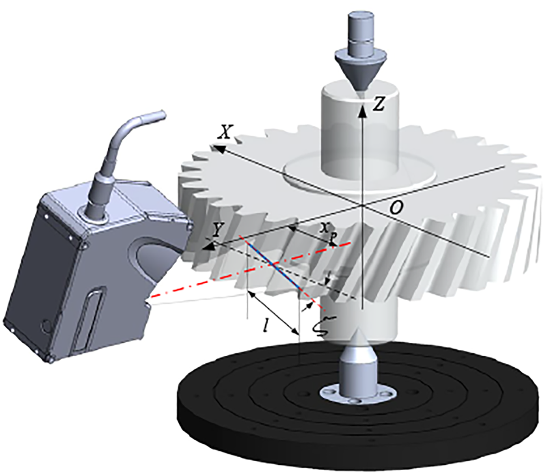
l represents the length of the measuring range. x p is the offset along the X axis. ζ is the setting angle of the sensor. During the gear measuring, the gear rotates around the Z axis and the line-structured laser sensor is stationary.
Projection analysis of cylindrical gear measuring with the line-structured laser sensor
When observing the gear measuring process facing the light source, the process could be regarded as a projection operation as in Figure 2. To show the process clearly, only three teeth are visible in the figure. The projection of the measuring light plane from the line-structured laser sensor is the straight-line L on the projection plane XOZ. When the tooth flank is projected on the plane XOZ, it is the area Σ enclosed by the projections of the tip helix and root helix. The projection of the left flank is marked as ΣL, which is area with the black section line. The projection of the right flank is ΣR, which is area with the red section line. As the length of the measuring range of the sensor is finite, the projection line of the measuring light plane is a line segment. The endpoints of line segment determine the range that the sensor could scan. The upper limiting line is Lup and the lower limiting line is Ldown. The intersecting part of the line L and the area Σ is the point clouds of the tooth flank. During the gear measuring, the line L is stationary on the plane XOZ as the sensor is stationary and the area Σ is moving on the plane XOZ as the gear rotates. The shape of the area Σ will change with the gear rotating to different angles. If the light occlusion is neglected, the line L scans the tooth flank to finish the measuring of the whole tooth flank in the measuring range. Because of the incident light occlusion, the overlapping zone of the area ΣL and the area ΣR will appear. This means that Tooth 2 will occlude the measuring light from hitting Tooth 3. Projection of the gear measuring with the line-structured laser sensor.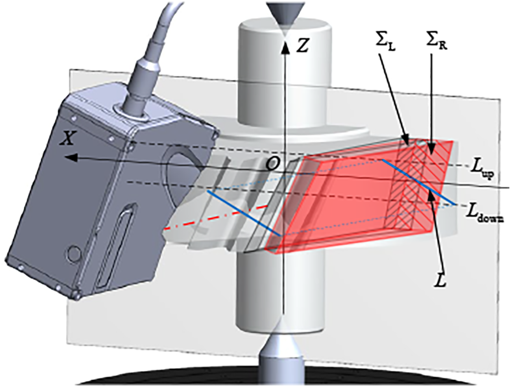
Process of the incident light occlusion
In the last section, it is mentioned that the tooth will occlude part of the measuring light, which will influence the gear measuring. This section will introduce the process of the incident light occlusion.
The right flank of Tooth 3 in Figure 2 is discussed here. According to the position of the teeth, it is easy to find that Tooth 2 will occlude the measuring light from hitting on the right flank of Tooth 3. To simplify the measuring process, only the projection of the measuring light and the flanks are studied in Figure 3. The blue line is the projection of the measuring light. The red curve is the projection of the tip helix of the right flank of Tooth 3 and the green curve is the that of the root helix. The black curve is the projection of the tip helix of the left flank of Tooth 2. The dotted lines are the limiting lines. When the gear rotates to different angles, the blue line will not change, but the shape and position of the red curve, green curve and black curve will change all the time. When the helix angle is bigger, the change becomes more obvious. The line segment AB is the occluded part on the right flank of Tooth 3. Projection drawing of the gear measuring.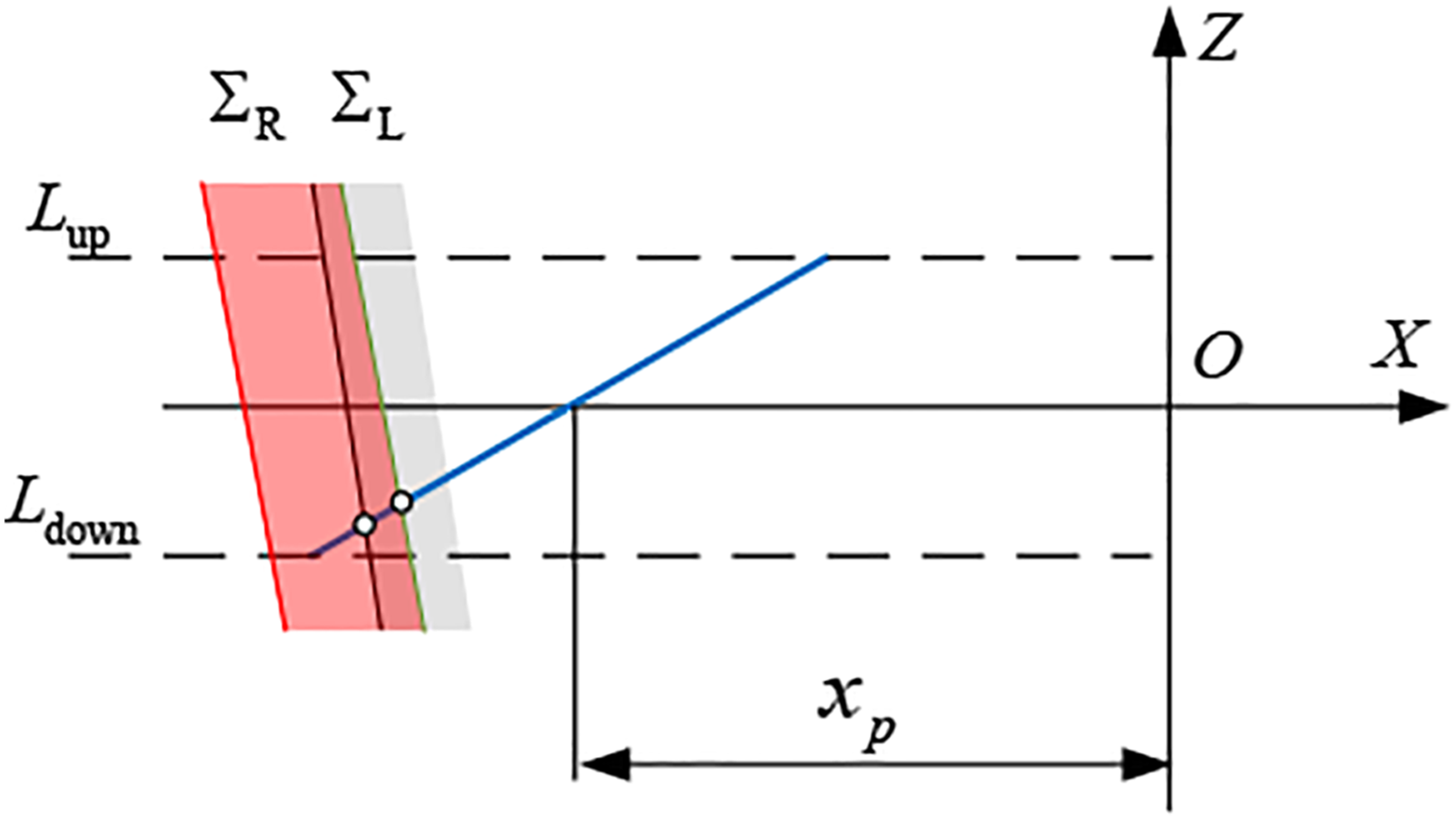
With the movement of the three curves, the flank will enter the measuring range of the projection of the measuring light. When the gear rotates, the black curve will go into the area between the red curve and green curve and the occlusion may occur. The incident light occlusion will not exist during the whole process. If the blue line scans the area ΣR first and then the black curve enters, the incident light occlusion will not happen because the area which the black curve scans has already been measured. Therefore, only when the black curve scans the area ΣR before the blue line, the incident light occlusion will take place. In order to illustrate the process more clearly, Figure 4 shows the projection drawings at different rotation angles. Figure 4(a) is the status before measuring of the right flank of Tooth 3. Figure 4(b) show that the flank is measured without the incident light occlusion. Figure 4(c) is the start of the incident light occlusion where the projections of the root helix of Tooth 3, tip helix of Tooth 2 and measuring light intersect at one point. Figure 4(d) is the incident light occlusion. Figure 4(e) is the finish of the measuring and the right side of the line segment AB will all become the incident light occlusion zone. No more data will be acquired. Figure 4(f) is that the flank leaves the measuring status. Incident light occlusion at different angles.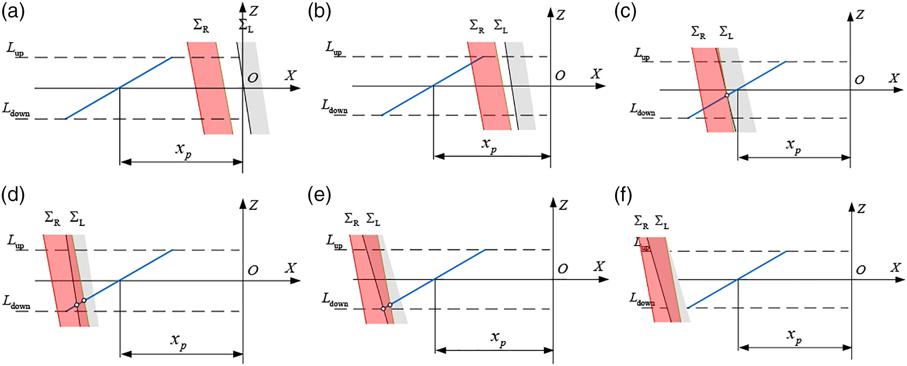
According to the above analysis, the position of the line segment AB will change with the rotation of the gear. All the line segments of AB form the incident light occlusion zone as in Figure 5. Point M
s
is the start point of the zone and Point M
e
is the end point of it. The segment M
s
M
e
is the trajectory of Point A, the boundary of the zone. The model of the zone should be built up as the size of it will determine the measurement process plan. Process of incident light occlusion zone.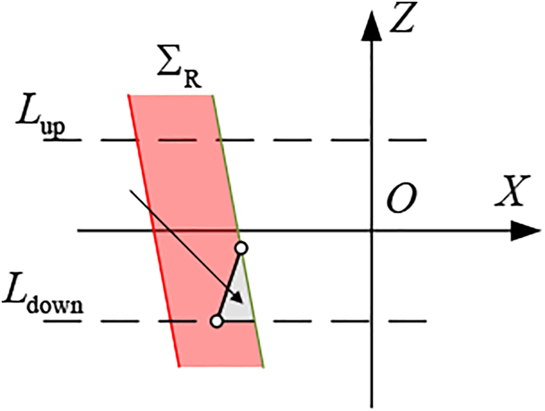
Model of the incident light occlusion zone
To build up the model of the incident light occlusion zone, the model of the tooth flank, the projections of measuring light plane and helixes, and the start angle and end angle of the incident light occlusion are introduced.
Model of the cylindrical gear tooth flank
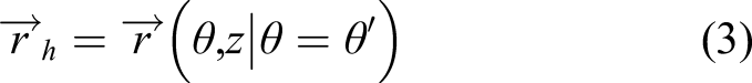
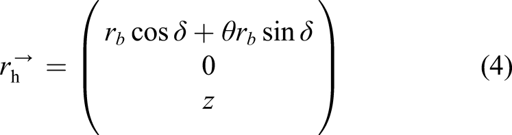
More than 95% of the cylindrical gears in the industry are involute helical gears. The gear tooth flank is an involute helicoid which is formed by rotating a straight-line around the base cylinder for a pure roll with a constant angle from the axis of the cylinder, as in Figure 6. Two variates are used to build up the model of the tooth flank. One is z which represents the position in the Z axis. The other is roll angle θ. Model of the involute helicoid.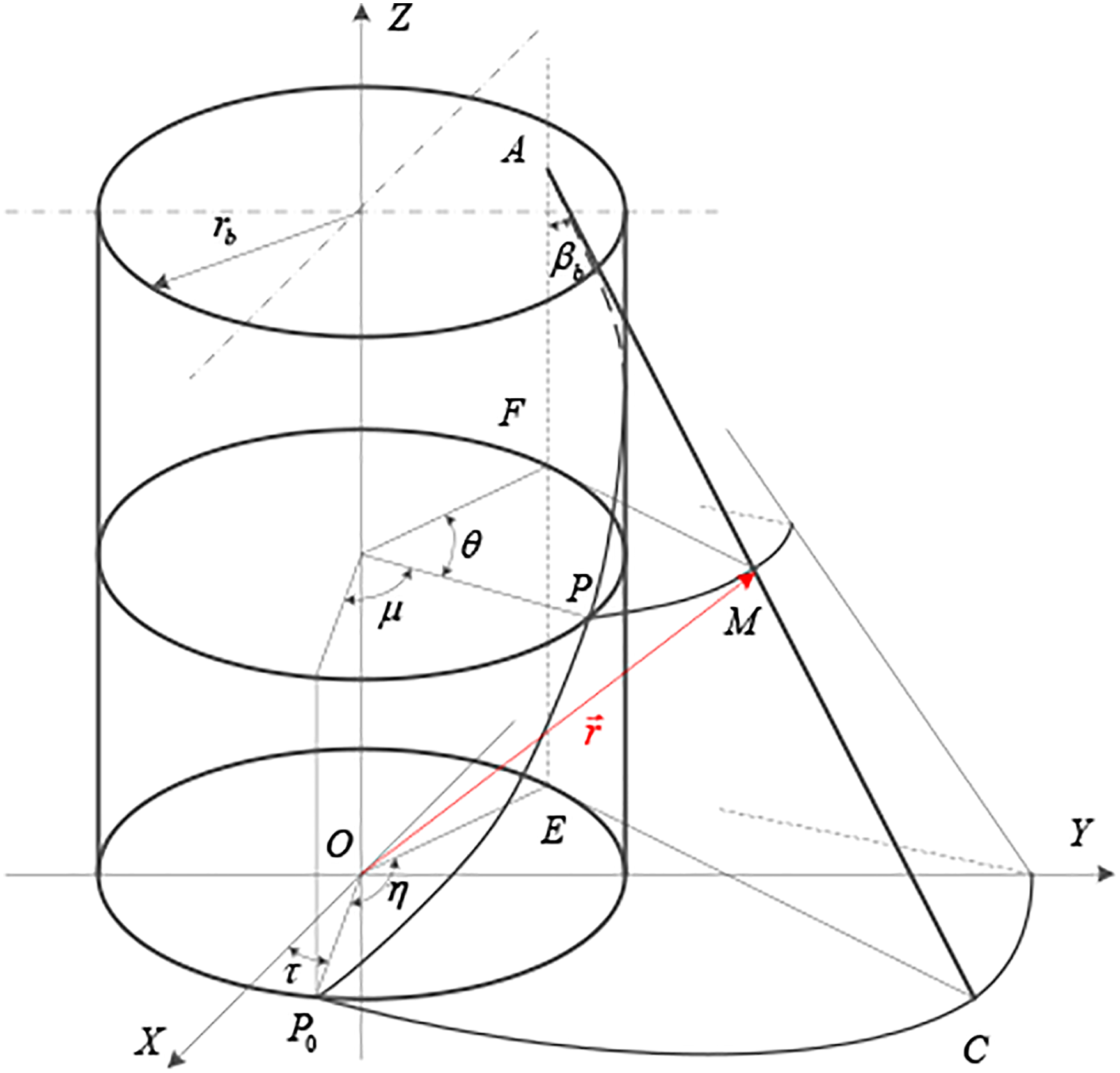
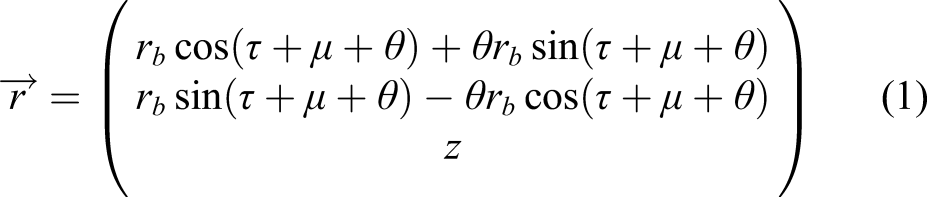
In Figure 6, Point M is any point on the tooth flank. Its formula is as follows
20
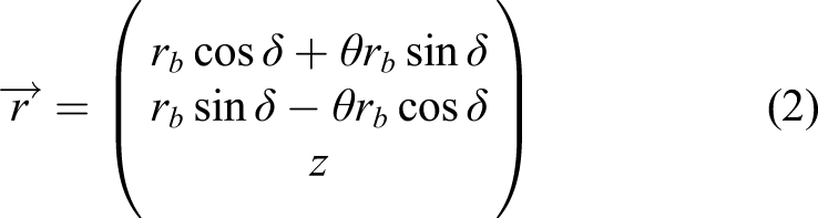
In the formula,
The incident light occlusion is a macro phenomenon and the gear modification are micro topography which will not impact on the occlusion process. The modification could be ignored during modelling.
Projection model of the gear measuring
The models of the projections should be derived to obtain the model of the incident light occlusion zone. There are two kinds of curves, projection of the helix and that of the light plane.
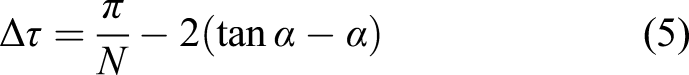
According to Formula (1), if the angel
When the angel
There are two important points to notice. One is that the flank is right or left flank. The other is the position angle

As the projection of the light plane on the plane XOZ is a straight-line, the formula of the projection is as follows.
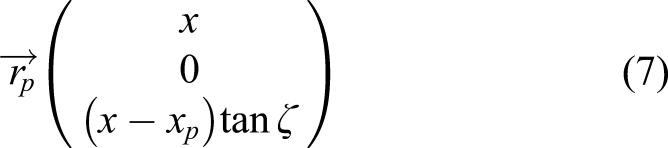
Combining Formulas (4) and (7), the coordinate of Point A could be determined. All the Point A form a trajectory on the right flank of Tooth 3. It is the boundary of the incident light occlusion. The right side of the trajectory is the incident light occlusion zone. When Point A is outside the tooth flank or the measuring range, the boundary will not work anymore. The start angle and end angle of the incident light occlusion are needed to confirm the size of the zone.
Start angle and end angle of the incident light occlusion
According to analysing the rule of the movement of the projections, it is obvious that the projection of the tip helix of Tooth 2, the projection of the root helix of Tooth 3 and the projection of the light plane intersect at one point as shown in Figure 4(c) when the incident light occlusion begins. This point satisfies the three formulas of the projections. It is simplified as Formula (8).
According to Formula (8), the start angle
When the incident light occlusion finishes, the projection of the tip helix of Tooth 2, the projection of the light and the lower limiting line intersect at one point as show in Figure 4(e). This point satisfies the three formulas of the projections. It is simplified as Formula (9).

For any position between the start angle and end angle, Tooth 2 will occlude the light from hitting to the right flank of Tooth 3. The intersecting Point A is the demarcation point of the incident light occlusion. This point satisfies the two formulas of the projections. It is simplified as Formula (10).
All the Point A between Point
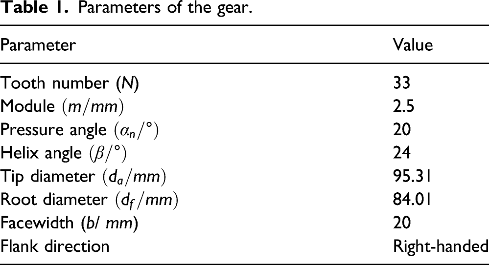
Parameters of the gear.
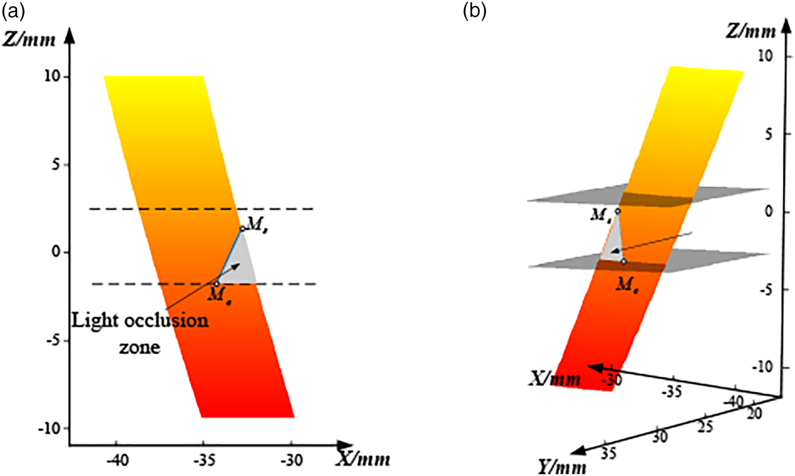
Boundary of the incident light occlusion on the tooth flank.
Experiment
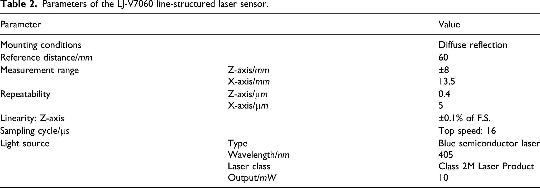
To prove the validity of the incident light occlusion model, measuring experiments are conducted. The measuring equipment is shown in Figure 8. The LJ-V7060 line-structured laser sensor is equipped on GMC. The parameters of the sensor are listed in Table 2. Measuring experiment. Parameters of the LJ-V7060 line-structured laser sensor.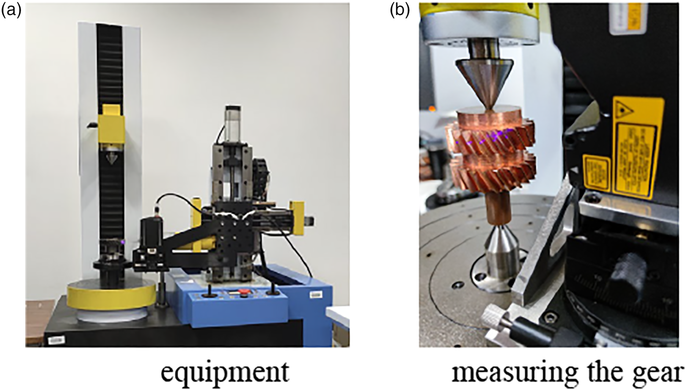
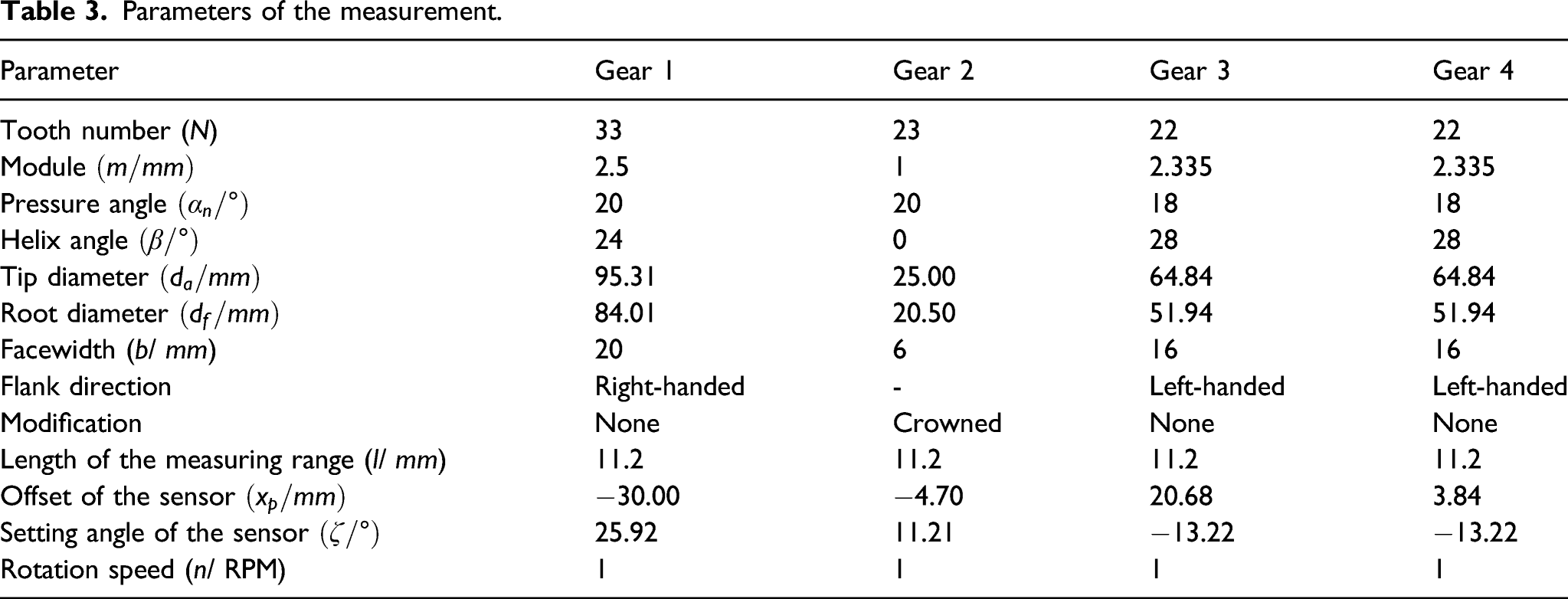
Parameters of the measurement.
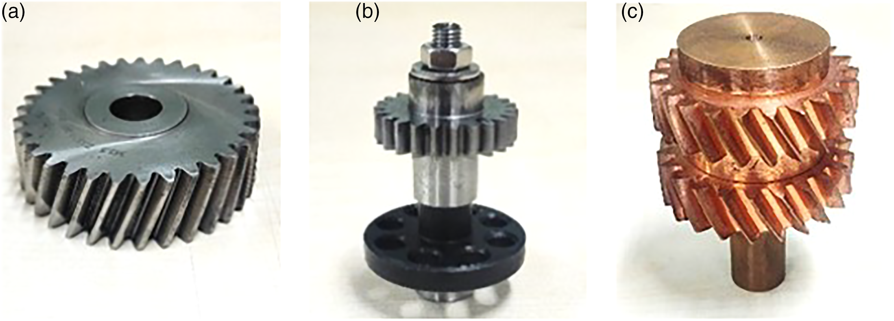
Measured gears.
After the scanning, the point clouds are acquired. For example, the data of Gear 1 is in Figure 10. One of the flanks is extracted from point clouds to compare with the proposed model. The axis of the point clouds is overlapped with the axis of the theoretical involute helical gear. The point of the data on the reference circle on the middle plane is rotated to the point of the theoretical gear at the same position. The extracted point clouds are compared with theoretical flank as Figure 11 Measured point clouds. Measured incident light occlusion zone compared with the theoretical one.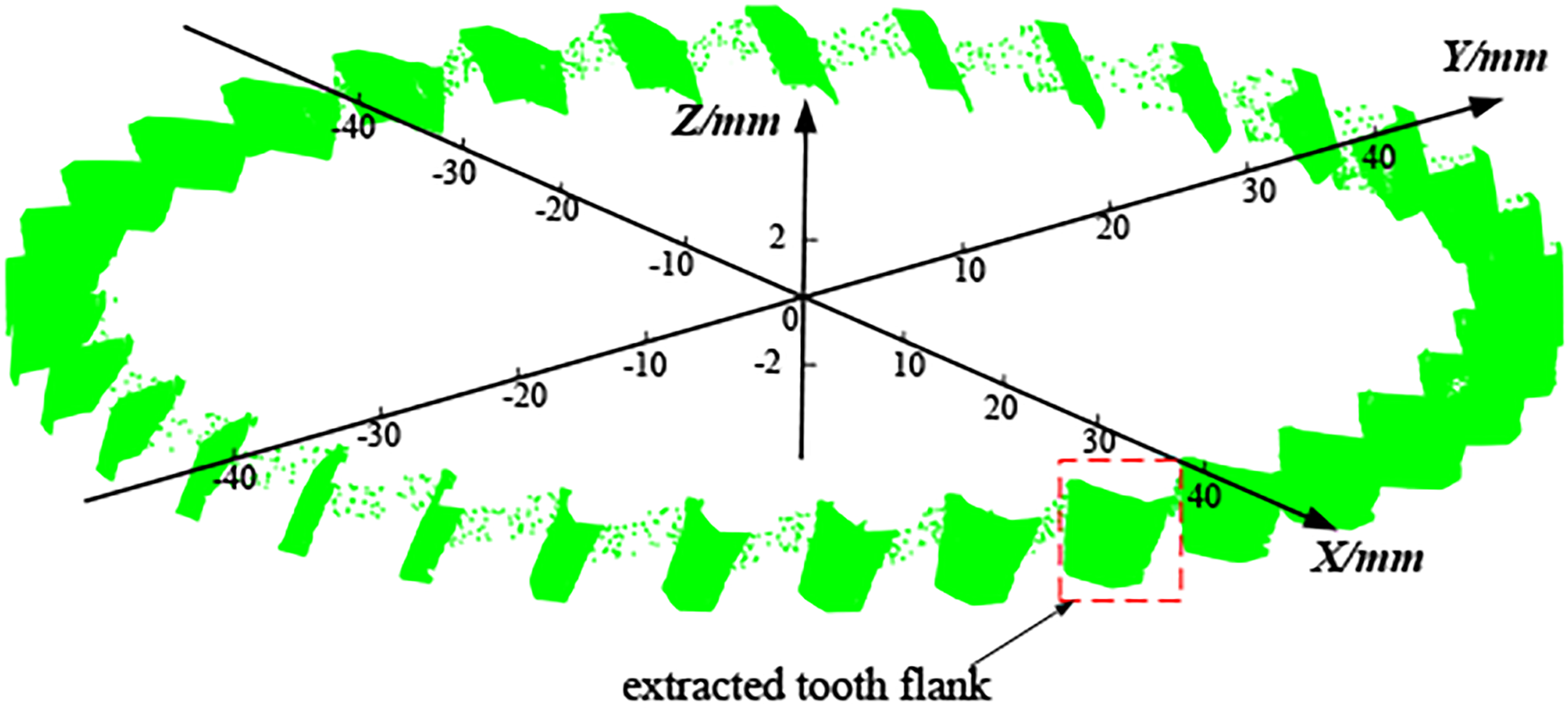
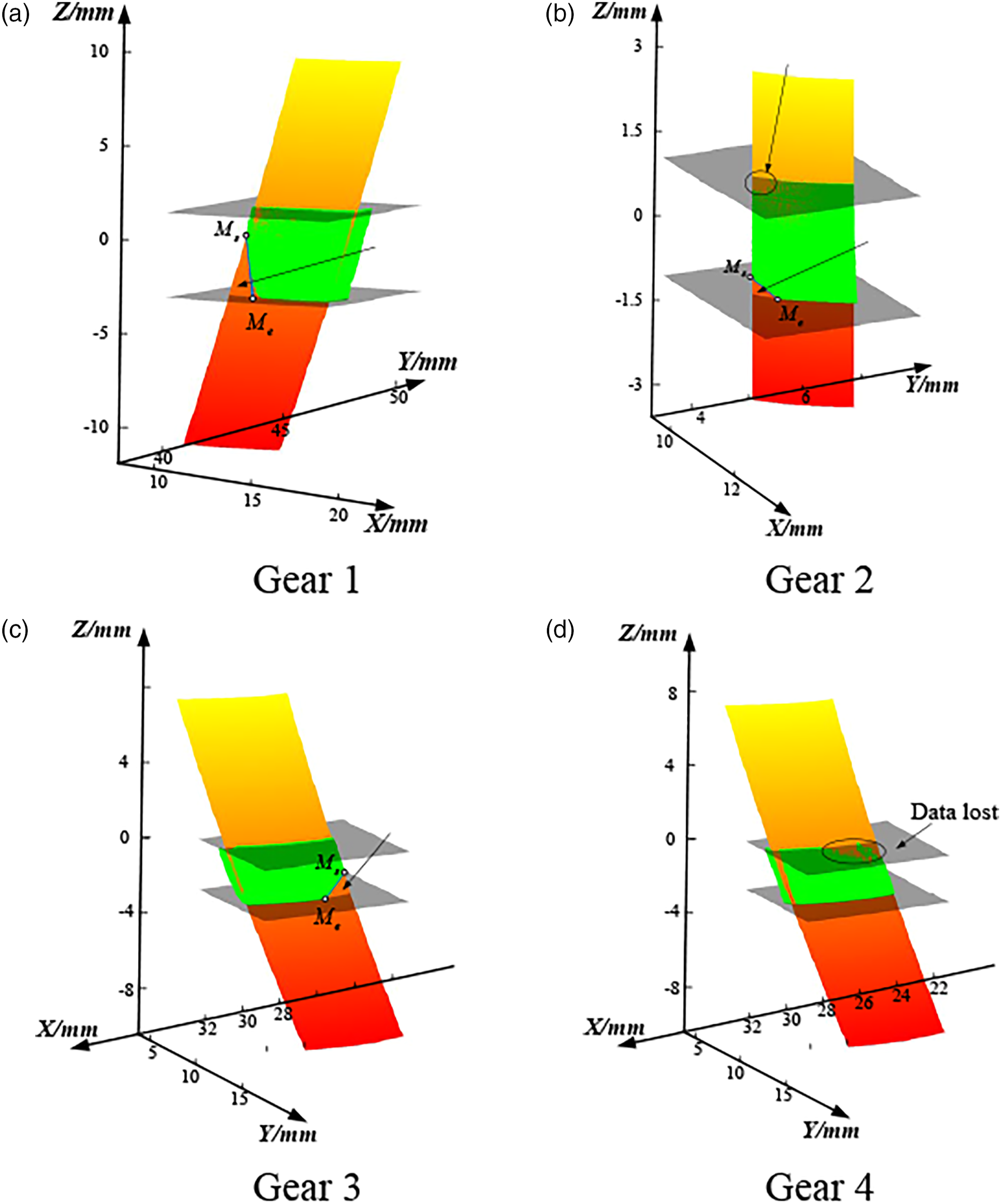
Figure 11(a)–(d) are corresponding to Gear 1, Gear 2, Gear 3 and Gear 4. The green points are the measured data. The blue curve is the theoretical boundary of the incident light occlusion zone. Figure 11(a) is the result of the right-handed cylindrical gear with diameter 95.31 mm and module 2.5 mm. The measured points almost overlap the theoretical model. There is no data in the theoretical incident light occlusion zone. The few points around the boundary which come from the secondary reflecting or diffraction of the light are invalid points. In addition, part of the points in the area near the lower limiting line are lost because the light is occluded when it goes back to the sensor. Figure 11(b) is the result of the spur gear with diameter 25.00 mm and module 1.00 mm. The measured incident light occlusion zones coincide exactly with the model. It verifies that the proposed model could apply to spur gears. In addition, some of the data are lost near the upper limiting line and the root because the angle between the measuring light of the sensor and the normal direction of the tooth flank is larger than the threshold value (70–80°). Gear 2 is a gear with crowned modification. The influence of the modification could be ignored. Figure 11(c) and (d) are the results of the left-handed cylindrical gear with diameter 64.84 mm and module 2.335 mm. The offset of Gear 3 is 20.68 mm. The measured result coincides with the theoretical result. It is verified that the model could apply not only to gears with different sizes, but also to gears with different parameters. The offset of Gear 4 is 3.84 mm which is quite small. There is no incident light occlusion with this offset. But for this offset of the sensor, the angle between the measuring light and the normal direction of the tooth is larger than Gear 3. Especially for the points near the upper limiting line and the root, more data are invalid.
Analysis of the influence factors of the incident light occlusion
As the incident light occlusion model is verified, the influence factors of it could be analysed based on the model. When the gear parameters and the type of the sensor are determined, only the installation parameters will impact on the size of the incident light occlusion zone. They are the offset and the setting angle of the sensor.
Influence caused by the offset of the sensor
The offset Start points for different offsets.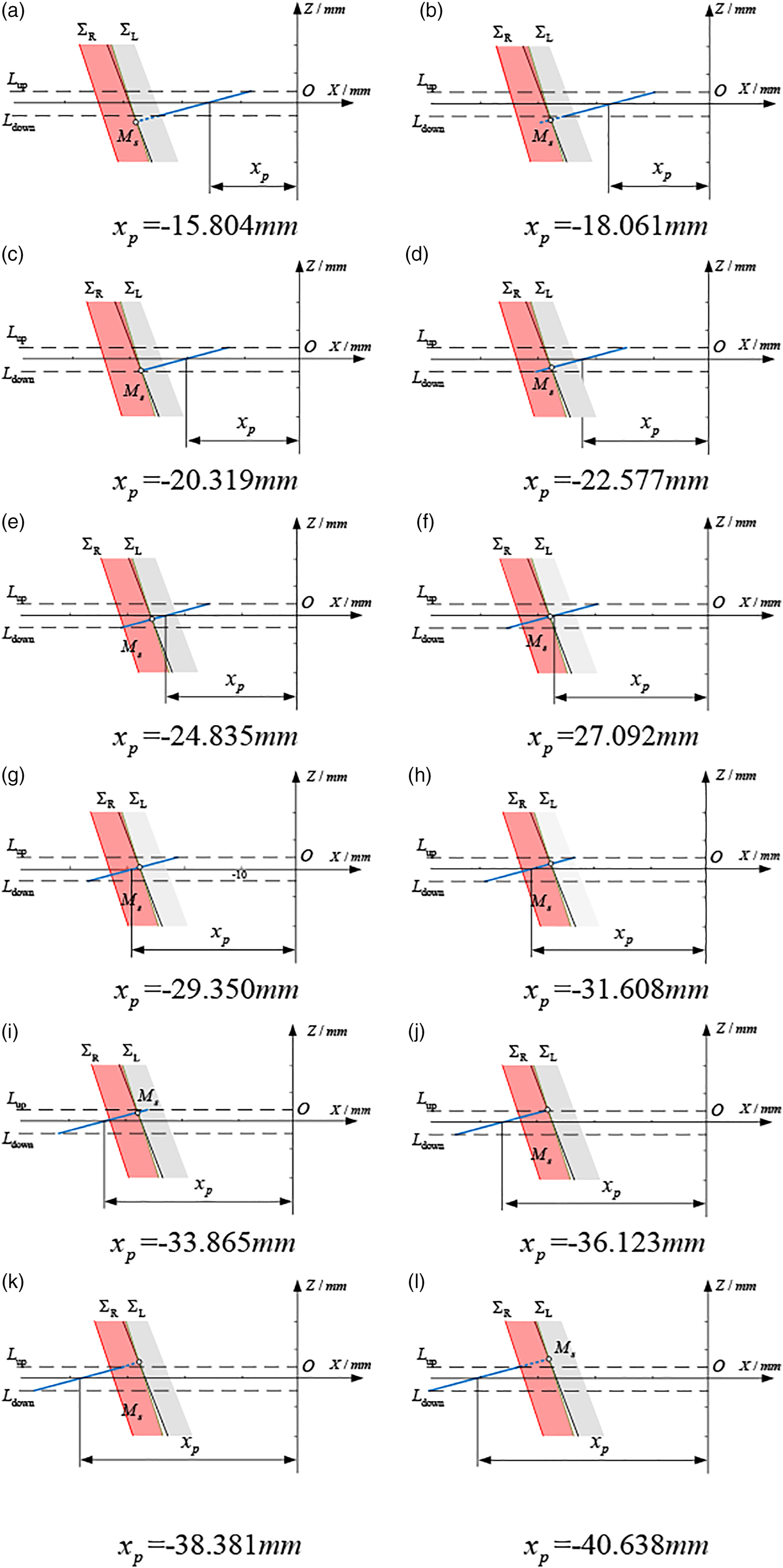
Figure 13 is the incident light occlusion zone of the gear measuring with the twelve offsets in Figure 12. According to Figure 12, it is already known that there is no occlusion in Figure 13(a)–(c). The shapes of the incident light occlusion zone in Figure 13(d)–(i) are similar to the triangle as discussed in Model of the incident light occlusion zone. The zone increases when the offset increasing. From Figure 13(j)–(l), it shows that the intersections are above the upper limiting line. The shapes of the zones are like the trapezoid in these figures. The zone also increasing with the offset. The boundary of the zone becomes more curved. This is because the projection of the helix is a sine wave. When the offset increases, the projection is closer to the peak of the sine wave. The curvature at the peak is much bigger than that near the zero point. The incident light occlusion zones in Figure 13(k)–(l) are too large so that the offsets are not suitable for measuring gear without any other adjustment. Incident light occlusion zone for different offsets.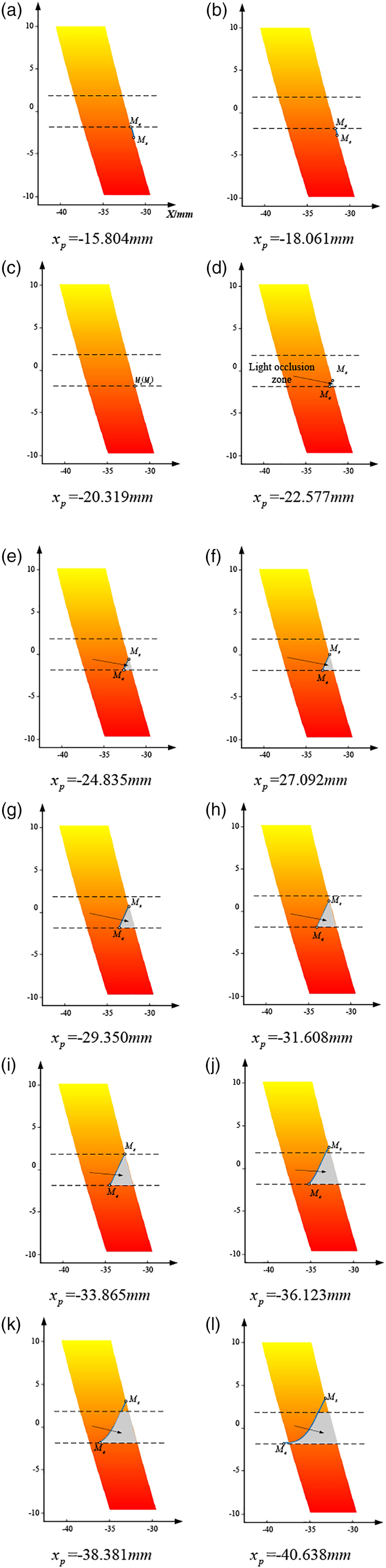
The area of the incident light occlusion zone and the proportion Area and proportion of the incident light occlusion zone for different offsets.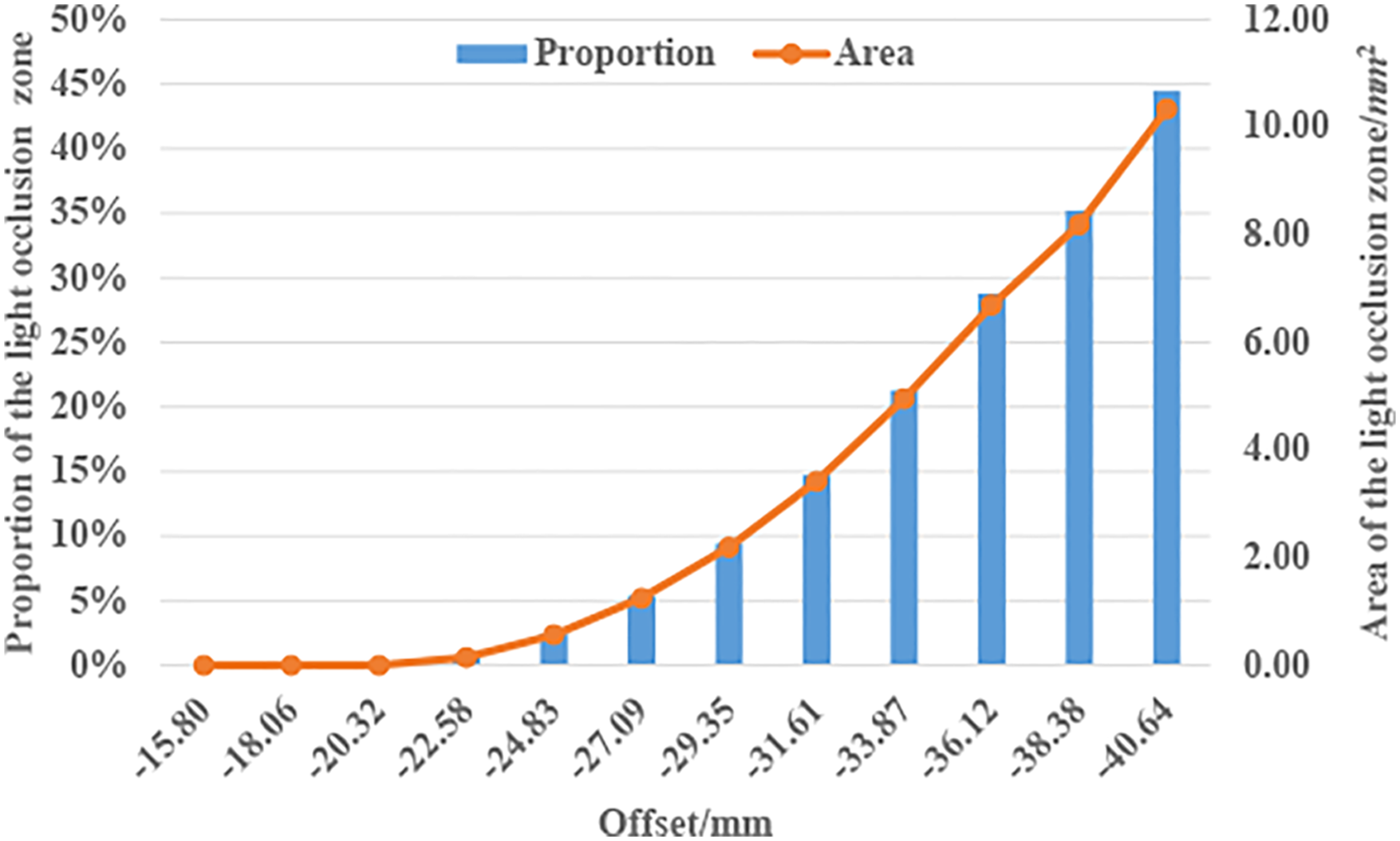
Influence caused by the setting angle of the sensor
Six setting angles Incident light occlusion zone for different setting angles.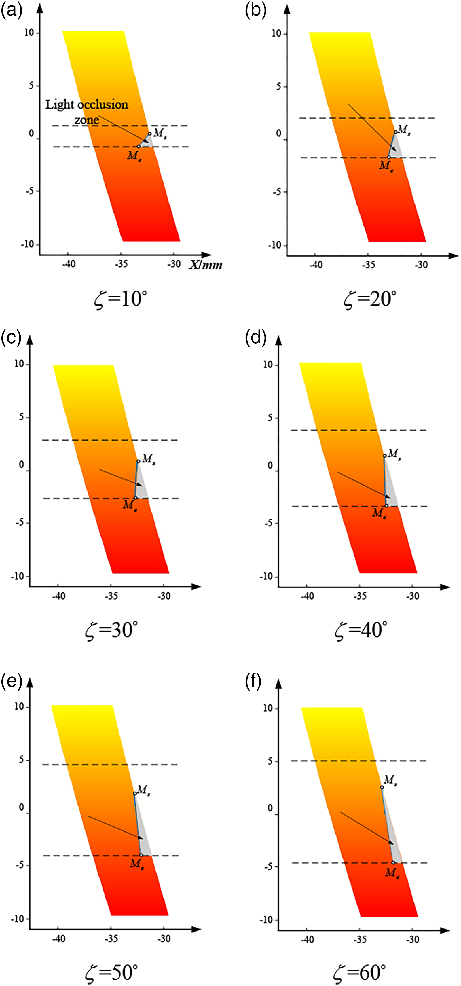
The proportions of the incident light occlusion zones for the six setting angles are in Figure 16. The figure illustrates that when the setting angle is bigger, the proportion of the incident light occlusion zone is smaller. At the same time, the measuring range is also larger. It seems that the measuring efficiency is improved. However, this also brings some new problems. First, the density of the measured points along Z axis decreases. Then, the bigger setting angle enhances the possibility of the second incident light occlusion. At last, although the proportion of the incident light occlusion zone decreases, the occlusion zone near the root of the flank becomes wide. This situation is not easy to de improved by adjusting the control measuring process. Proportion of the incident light occlusion zone for different setting angles.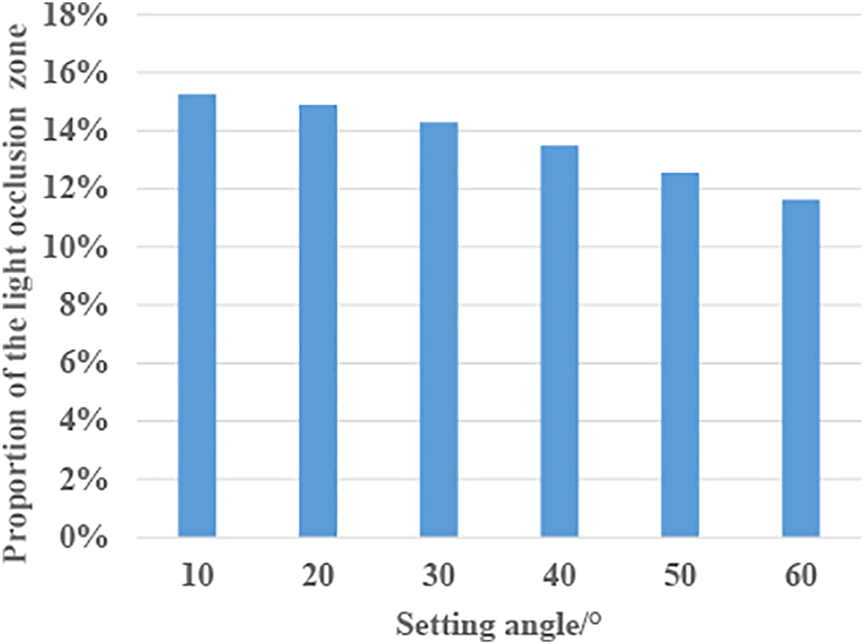
Conclusions and outlooks
(1) This article analysis the incident light occlusion process when measuring the gear with line-structured laser sensor which is quite important but other researches don’t discuss it. For understanding the phenomenon more clearly, the model of the incident light occlusion zone is built up. According to four measuring experiments, it is verified that the model could universally apply to spur gears or helical gears with different sizes and parameters. The impact of modification to the incident light occlusion could be ignored. Comparing the experiment of Gear 3 with that of Gear 4, we could find that the data of the sensor will be invalid when the offset of the sensor is smaller than a threshold value. (2) The following conclusions are drawn from discussion on the influence of the offset and setting angle of the sensor. The decrease of the offset is helpful to reduce the area of the incident light occlusion zone. When the offset is small enough, the incident light occlusion could be avoided. This could increase the measuring speed effectively. Then, although the increase of the setting angle could reduce percentage of the incident light occlusion zone, the occlusion near the root will become more serious. This makes it hard to compensate the incident light occlusion with control route planning. (3) During the study, we find that not only the incident light will be occluded, but also the reflected light will be. This could be a future direction to study the gear measurement with the line-structured laser sensor.
Footnotes
Declaration of conflicting interests
The author(s) declared no potential conflicts of interest with respect to the research, authorship, and/or publication of this article.
Funding
The authors disclosed receipt of the following financial support for the research, authorship, and/or publication of this article: This work was funded by National Key R&D Program of China (2018YFB2001400) and National Natural Science Foundation (52175036).