The work presented here deals with the trajectory-tracking control of omnidirectional mobile robots using a novel robust control technique. The aim is to achieve good tracking performance in the presence of frictional forces and torques, uncertainties, and saturated control inputs. First, a dynamic model of the omnidirectional mobile robot incorporating motor dynamics and frictional forces and torques is derived leading to a higher order system model. Subsequently, a novel cascaded sliding-mode tracking control scheme is proposed to perform trajectory-tracking with the omnidirectional mobile robot, which includes direct and indirect sliding-mode controllers in a cascaded structure. The indirect sliding-mode controller is utilized to attain tracking of the indirect reference input (i.e., desired trajectory) in the first subsystem and constitutes a direct reference input for the second one. A direct sliding-mode controller (i.e., actual control) is then designed to achieve tracking of the direct reference input. This way, the indirect reference input can be effectively manipulated through the proposed cascaded sliding-mode tracking control and individual subsystems are guaranteed to have not only Uniform Ultimate Boundedness but also asymptotic convergent performance. The stability of the closed-loop system is demonstrated via the Lyapunov stability criteria and validated through simulations. It is shown that the cascaded sliding-mode tracking control leads to good trajectory-tracking performance in the presence of uncertainties, friction, and saturated control input.
For the past decade or so, many mobile robots with omnidirectional wheels have surfaced in the literature and many studies have been conducted to analyze and control them in various ways. Attention directed toward OMRs is due to their unique ability to move in any direction. Particularly, they are capable of moving in directions perpendicular to their driven wheels which is not the case with non-holonomic mobile robots. Their ability to simultaneously rotate and translate allows them to move in arbitrary directions and navigate smoothly through confined space which cannot be achieved with differential-drive mobile robots (DDMRs), for example.1,2 This agility of OMRs comes with an increase in complexity of both the modeling and the control schemes. In this work, a mobile robot with three omnidirectional wheels is developed whose equation of motions include motor dynamics and frictional forces and torques. A cascaded sliding-mode tracking controller (CSMTC) is designed here for the OMR to overcome frictional forces and torques and attain good trajectory-tracking performance. The main difference between the proposed CSMTC and the ordinary SMC is the control design procedure. The SMC is usually applied to the whole closed-loop system, whereas the CSMTC is carried out in steps using individual subsystems. The flexibility of the CSMTC makes it more suitable for complex dynamic systems where the closed-loop is too complex to study in one shot such as the OMR system described in the manuscript. Many research findings are available in the literature about OMR control and a representative few will be discussed here.
It is well known that frictional forces and torques hamper the motion of OMRs and degrade their closed-loop performance. Therefore, it is extremely important to mitigate the effect of friction on OMRs to improve their trajectory-tracking control performance. A model-predictive control (MPC) scheme with friction compensation was proposed by Júlio et al.3 to achieve trajectory-following of an omnidirectional three-wheeled robot. A cascaded control configuration was adopted to generate the velocity references for the proposed MPC and simultaneously compensate the effect of static friction. In Ref.[4], the modeling and robust low-level control of a redundant mobile robot with four omnidirectional wheels subject to parameter uncertainties resulting friction forces was presented. The designed controller led to better performance compared to other controllers available in the literature. Recently, Ren et al.5 presented a reduced-order, extended state observer-based, sliding-mode control scheme for friction compensation in a three-wheeled OMR system. The advantage of the proposed control scheme is that it does not require an explicit friction model and it is computationally less intensive than some other techniques, such as MPC.6,7 It is clear from Refs.[4 and 5] that closed-loop performance improves when friction forces and torques are directly addressed in the control design.
Recently, a brain-emotional-learning-based intelligent controller inspired by a computational model of a limbic system was utilized in an omnidirectional mobile robot.8,9 Kim and Kim10 presented an online minimum-energy translational and rotational velocity trajectory planning and tracking control for OMRs. The simulation and experimental results showed that the proposed controllers led to better performance, energy saving, and loss-minimization compared to traditional controllers. Huang et al.11 designed a management algorithm to monitor the switching between a set of controllers for an OMR with structured and unstructured uncertainties. One of the controllers is an adaptive sliding-mode controller to be used near singularity and the other one is a robust controller used to mitigate the effect of the unstructured uncertainty. In Ref.[12], the authors presented a singularity analysis and trajectory-tracking controller using a kinematic model for a mobile robot equipped with Swedish wheels. It is worth noting that relevant research findings available in the literature did not account for actuator dynamics and friction forces and torques simultaneously. In addition, the associated control algorithms developed therein necessitated further simplifications in the control design model. It is well known that the closed-loop performance is dependent on the accuracy of OMR dynamic model especially when the vehicle operates at high speeds.13–15 Motivated by the aforementioned research findings, a cascaded sliding-mode tracking control (CSMTC) scheme is developed for an OMR system, which includes actuator dynamics and frictional forces and torques models, in the presence of random uncertainties and saturated control inputs. The controller design is based on the work we developed in Ref.[2].However, even though the control design procedure is similar, the actual system is different and more complex. Therefore, the closed-loop system is more complex in the current work and requires rigorous proofs of stability and robustness which is the subject of this manuscript. Moreover, the work in Ref.[2]is developed for under-actuated systems; however, the omnidirectional robot used in this work is fully actuated. It is worth noting that the CSMTC is less conservative than the controller developed in Ref.[2] and can be applied to many other systems with similar nonlinear dynamic models.
The dynamic model of the OMR system is very complex and requires sophisticated control techniques to perform tracking control. Adding to the complexity is friction forces and torques, random uncertainties, control input saturation, measurement noises. These hard nonlinearities restrict the ability of available nonlinear control techniques to achieve trajectory tracking with reasonable speeds. To the best of our knowledge, no work has been done before on omnidirectional robots with all of these hard nonlinearities included in the closed-loop system. The advantage of the proposed CSMTC is that it designs the overall control inputs by focusing on individual subsystems rather than the overall closed-loop system. The proposed strategy makes it very suitable for complex dynamic systems such as OMR delineated in the work presented here. The high level of robustness exhibited by the CSMTC as well as its good trajectory-tracking performance makes its implementation in real time a very viable solution. The contributions of this work presented here are as follows:
(1) Derive a comprehensive model for an OMR system which includes motors’ dynamics and, friction forces and torques.
(2) Design a cascaded controller (CSMTC) for the closed-loop system with a high level of robustness.
(3) Design a compensator to mitigate the effect of friction forces and torques available in real life systems which usually are the cause of performance degradation.
The rest of the paper is organized as follows: the OMR’s dynamic model and problem statement are presented in the Modeling of an omnidirectional mobile robot and problem statement section. The CSMTC design is delineated in the Cascaded sliding-mode tracking control design section and the required theorems and the associated proofs are presented therein. The Simulations and discussions section shows the simulation results and corresponding discussions. Finally, in the final section, some concluding remarks are made.
Modeling of an omnidirectional mobile robot and problem statement
Modeling of an OMR
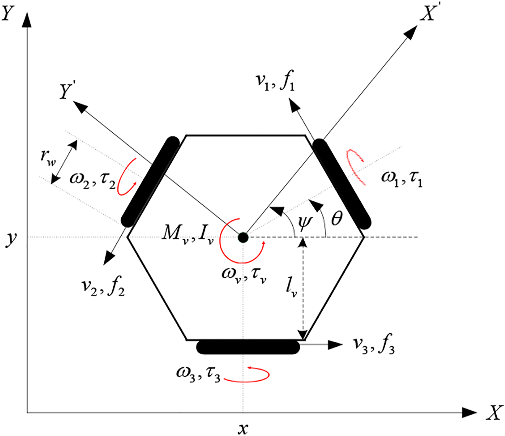
Referring to the schematic of an OMR shown in Figure 1, and using the inertial frame, , and the robot body frame, the velocities equations can be written as
where , , and represents the linear and angular velocities of the OMR with respect to the center of mass of the robot. The friction forces and torques lead to the following equation of motion
where and represent the mass and moment of inertia of the OMR; , , , , and represent the applied force (in the and directions), applied torque, friction force (in the and directions) and friction torque imposed on the center of mass of the OMR, respectively; and can be represented as follows
where and , are the forces and torques exerted by each wheel; and are the friction forces and torques of each wheel; is the distance between the wheel and the center of mass of the vehicle; and is the radius of the wheel. From the geometric relations, the following equations can be obtained
where .
Schematic diagram of an OMR.
The dynamics for each separate wheel around the wheel’s axis can be written as
where and are the moment of inertia of the wheel and applied friction torque at the wheel, respectively. Similarly, the relationships between the linear and angular velocities of the wheels can be expressed as
The linear velocities of the wheels with respect to the center of mass of the OMR can be written as
In addition, the nominal friction forces and torques of the wheel are, respectively, modeled as
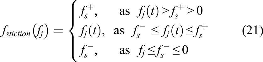
where when and and, when and , otherwise; the slip forces and torques are modeled as
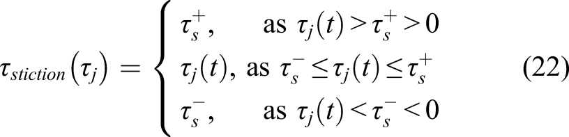
The stiction forces and torques in (17)–(18) are modeled as
For completeness of dynamic model of the OMR, the motors’ dynamic model are added and given by
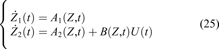
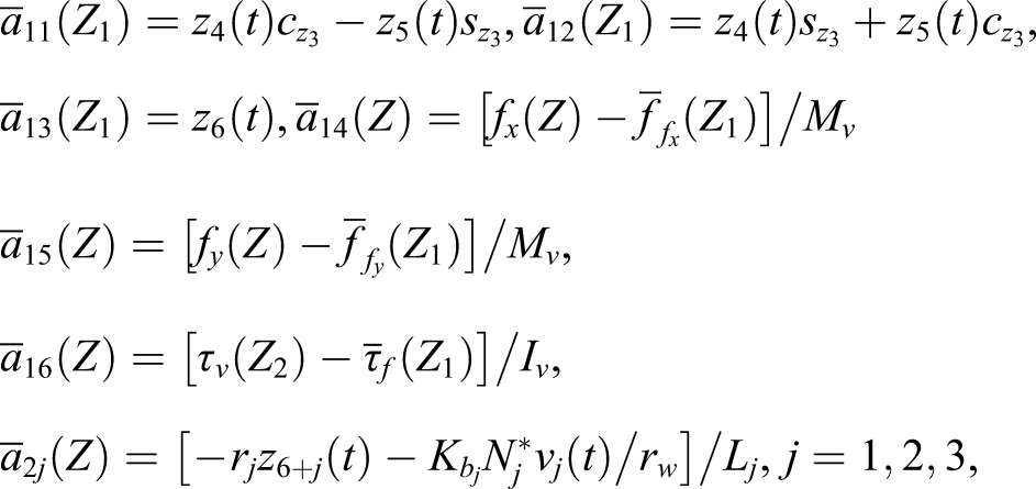
where and are the inductance and resistance of the armature circuit; respectively, for each motor attached to each wheel; is the total gear ratio of the wheel; is the gear ratio from the motor to the wheel; , , and are back-emf constant, torque constant, armature current and input voltage for each motor, respectively. Based on the system kinematics (1)–(3), dynamics (12), frictional forces and torques (17)–(18) and motor dynamics (23)–(24), the system state variables are defined as , , , , , , , , . The system dynamic equations of the OMR can be divided in two subsystems and described in state-space representation as
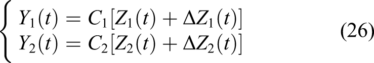
where are the system outputs and divided into indirect and direct outputs as
where is an indirect output based on the system kinematic and dynamic equations; is a direct output based on the motor dynamics. The outputs and are given by
and
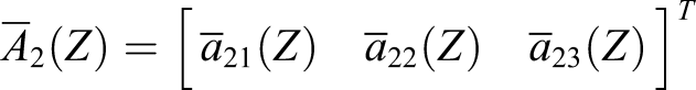
where and are measurement noises. The system functions include nominal and uncertain terms as . Similarly, the output gain includes nominal term and uncertain term as The nominal system matrices, are given by
where
and
and .
The dynamic system represented by (25)–(26) constitutes the complete model of the OMR system with uncertainties and friction forces and torques included. Using the system of equations (25) and (26), the control problem will be formulated in the upcoming sections.
Problem statement
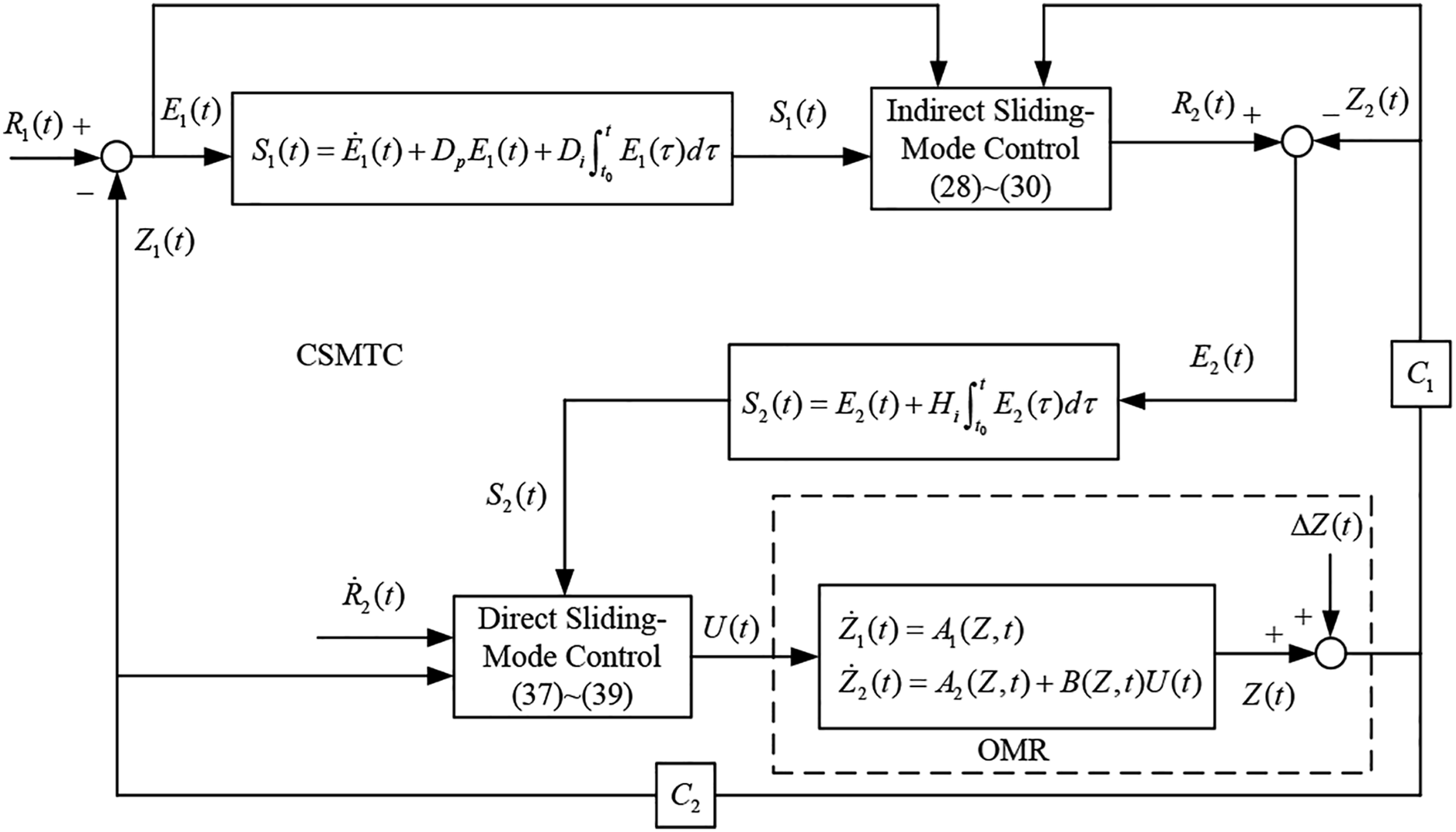
The control problem is to design a robust control input for the OMR system represented (25)–(26) such that the system’s indirect output including random uncertainties tracks an indirect reference input . To achieve this goal, an indirect sliding-mode controller (SMC) is first designed using the first subsystem of (25) as a direct reference input to the second subsystem of (25) (See Figure 2). This aim here is to make the indirect output track the indirect reference input . A direct SMC (i.e., ) is then designed to make track . This control structure is known as cascaded sliding-mode tracking control (CSMTC). The proposed CSMTC can indirectly and robustly manipulate the indirect reference input through . The overall trajectory-tracking control block diagram for the OMR is shown in Figure 2.
Overall control block diagram of an OMR.
Cascaded sliding-mode tracking control design
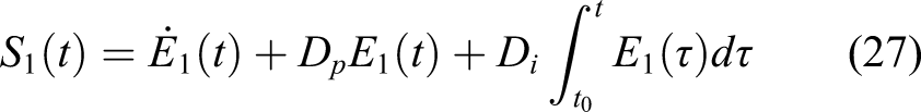
The proposed CSMTC is designed to achieve trajectory-tracking of an OMR system. First, the system’s tracking errors is defined as . Then, the first of the two sliding surfaces required for the CSMTC to manipulate the indirect output is selected as
where , and and are constant diagonal matrices which are selected such that the sliding surface is stable. The following lemma is needed for the tracking performance of the OMR.
Consider the dynamic equation given by where and are constant matrices, if the inequality for where is a positive constant and is satisfied by the input with a bounded initial condition then with a rate of for .16
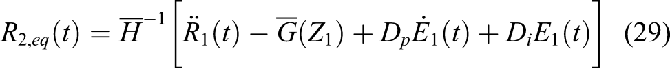
For the first subsystem equation in (25), an indirect sliding-mode control is designed such that as and serve as a direct reference input for the second subsystem in (25) as
where
is nonsingular, and stands for an exponentially convergent rate to reach the first sliding surface, is a switching gain which satisfies where , and is a boundary layer. The equivalent control part mainly copes with the nominal system, whereas the switching control part mitigates the effect of uncertainties and external noises. The following theorem is used to prove the uniform ultimate boundedness (UUB)17,18 and asymptotic convergence of the tracking error .
Applying direct reference input (28) to the first subsystem of (25) with the known upper bound of uncertainty, the first sliding surface will be reached and satisfy the following convex set
where
Consequently, the tracking error is UUB. Since where and is a positive constant and and then as Below is the Proof.
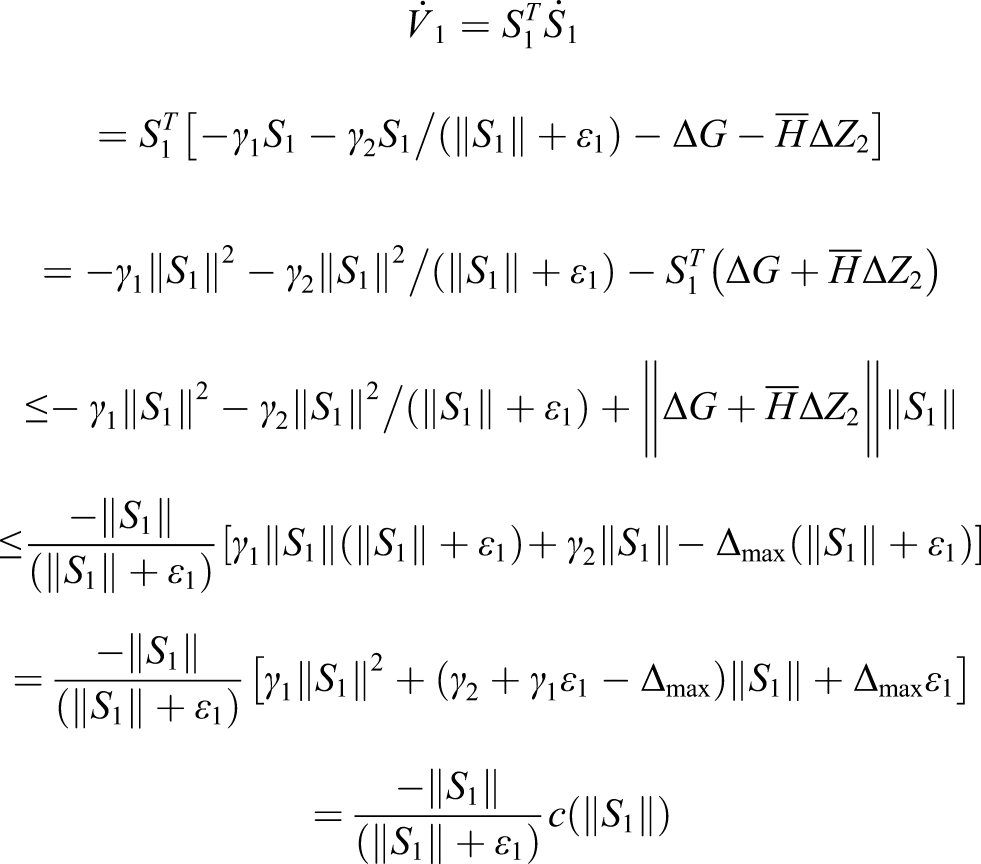
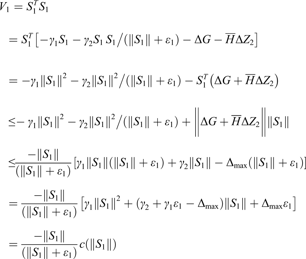
For the first subsystem, the indirect sliding-mode control is designed to achieve the tracking of an indirect reference. A Lyapunov function is defined as . Taking its time derivative with the substitution of (28) and known upper bound of uncertainties, that is, , yields the following result
where with and described in (33)–(35). As the inequality is satisfied. Thus, outside of the domain in (31) making is obtained. Therefore, the sliding surface asymptotic converges to the domain and then is UUB. Further, from Lemma 1, if for where and is a positive constant and where (i.e., ) with a rate of as Q.E.D.
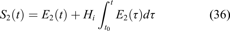
Subsequently, to achieve the tracking control of the direct reference input (28), a direct sliding-mode controller based on the second subsystem of (25) will be designed and used here. Therefore, the second sliding surface is designed to shape the system response as follows
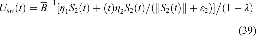
where , is a diagonal matrix chosen such that the sliding surface is stable. Similarly, the direct sliding-mode control input includes the equivalent and switching control parts and , respectively. and are, respectively used to cope with the nominal system and uncertain control gains as well as system uncertainties such that approaches asymptotically as
where
is a nonsingular matrix; represents a convergent rate exponentially reaching the sliding surface; is a switching gain; is a boundary layer and is an upper bound of the uncertain control gain and satisfies the following inequality
In addition, it is assumed that the uncertainty function has an upper bound, which satisfies the following inequality
where is a known positive function, and are constrained by the stability of the closed-loop system.
Applying the proposed direct sliding-mode control input (37) to the second subsystem (25) with the uncertain control gain (40) and the known upper bound of uncertainty (41), the second sliding surface will be reached and satisfy the following convex set
where
Consequently, the tracking error is UUB. Since where is a positive constant and then as The corresponding Proof is presented below.
For the second subsystem, the direct sliding-mode control is designed. Similarly, a Lyapunov function is defined as . Taking its time derivative with the substitution of (40) and known upper bound of uncertainties (41) yields the following result
where with and described in (44)–(46). As the inequality is satisfied. Thus, outside of the domain in (42) making is also achievable. Therefore, the sliding surface asymptotic converges to the domain and then is UUB. Similarly, if for where is a positive constant and then with a rate of as Q.E.D.
Simulations and discussions
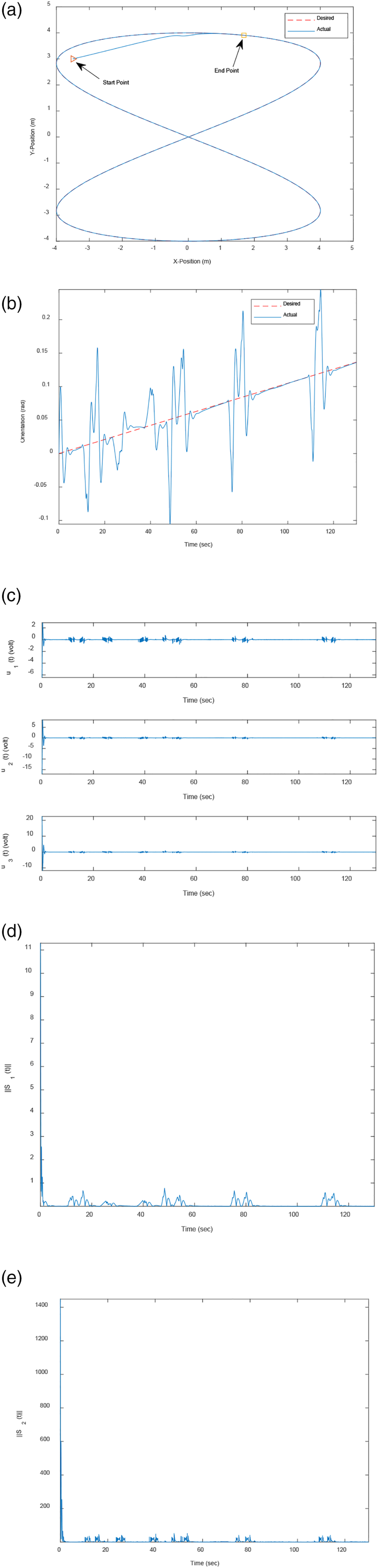
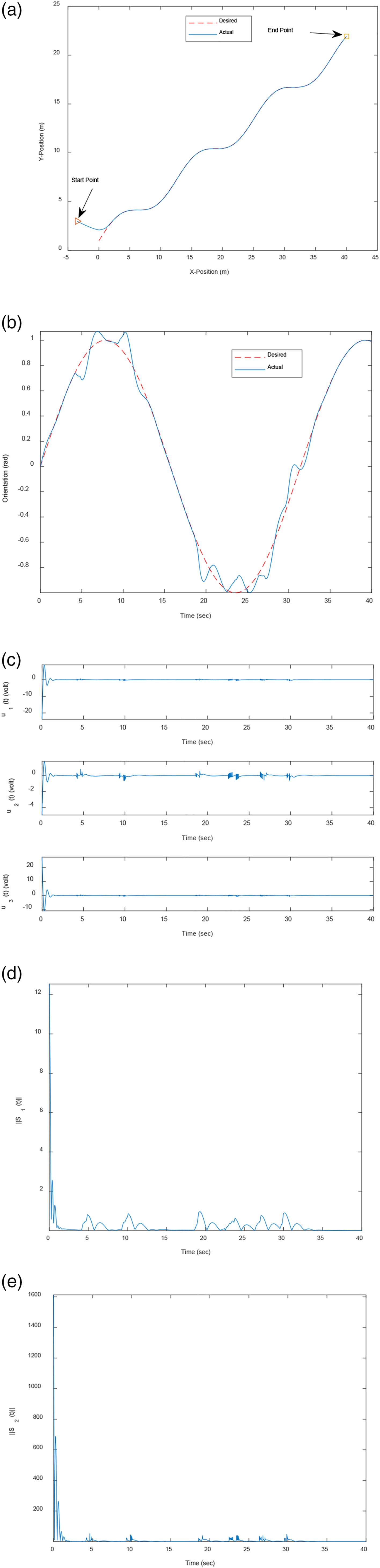
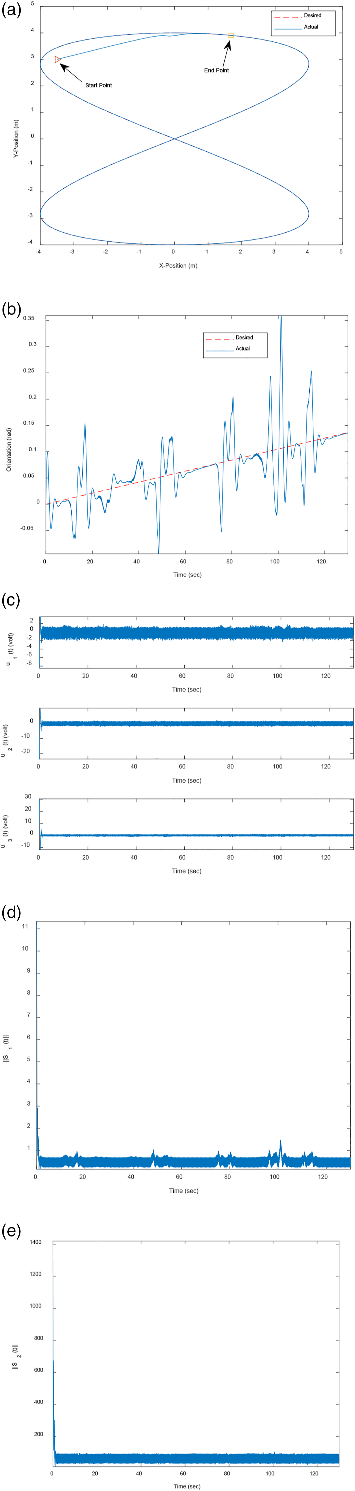
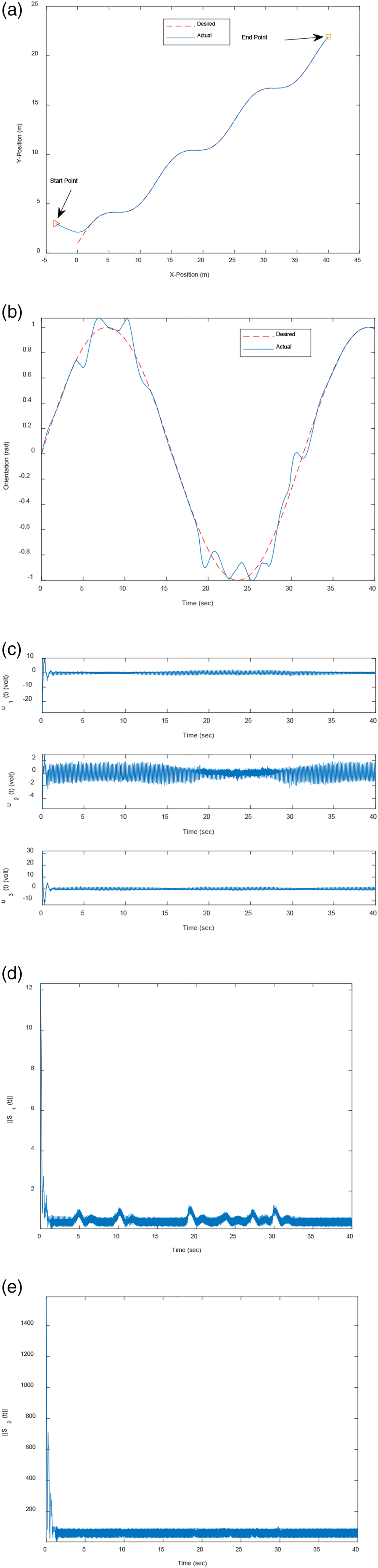
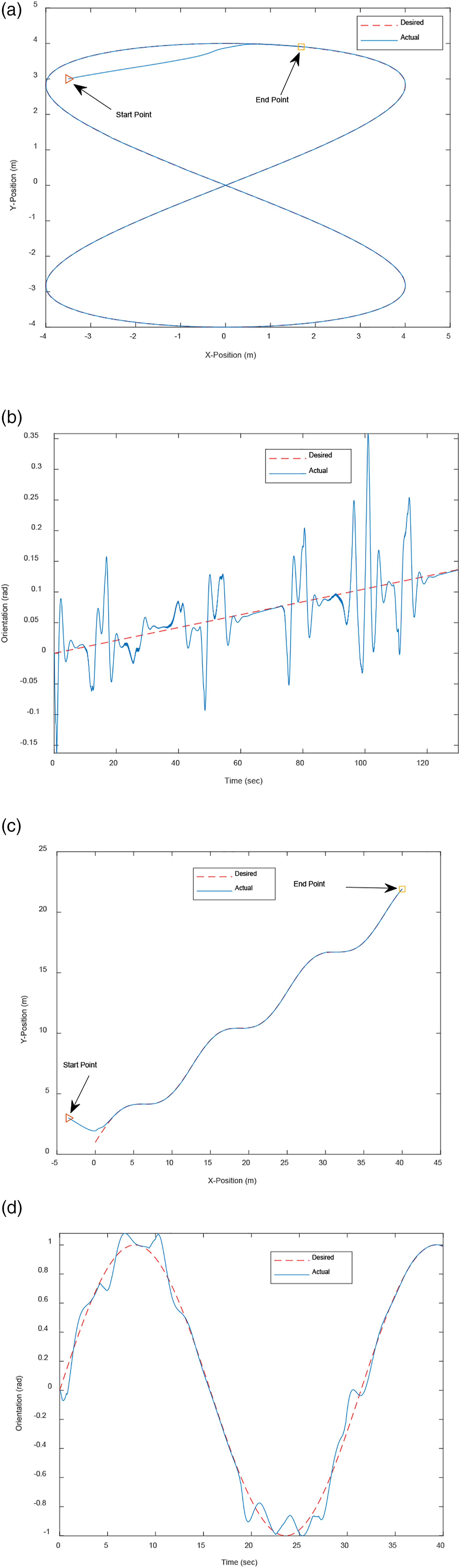
To evaluate the performance and verify the robustness of the proposed control technique, simulations for a planned trajectory-tracking of an OMR in the presence of a maximum 20% error of random uncertainties are conducted. In the simulations, the initial position and orientation of the OMR is taken as the sampling time is 0.01 s, and the following values for the system parameters19,20 are set as , , , , , , , , , , , , , , , , , , , , , , , , , , , . The control parameters are selected as , , , , , , , , , . Two desired trajectories are, respectively, planned: the first case is a figure-eight shaped trajectory which can be represented as (Case 1) where and the second case is an S-shaped trajectory; that is, (Case 2) where , . The measurement noises injected into the indirect and direct outputs are, respectively, and It is worth noting that the noise amplitude is dependent on the environment and road conditions where the OMR is operating. The chosen values are based on indoor environment settings. Therefore, reasonable noise levels coherent with laboratory settings are chosen, but a wide range of frequencies have been used in the simulations to represent different noise sources. First, the OMR system without random uncertainties and measurement noises is simulated and the results are shown in Figures 3 and 4. It can be seen from Figures 3 and 4, the tracking performances are excellent. In addition, the sliding surfaces (cf. Figures 3(d) and (e), Figures 4(d) and 4(e)) converge to a bounded domain as expected. Next, the effects of random uncertainties in the system functions and measurement noises in the system outputs are investigated. A maximum of 20% error of random uncertainties in the system functions (i.e., and ) and measurement noises to the system outputs are injected into the OMR system and the results are shown in Figures 5 and 6, respectively, for Cases 1 and 2. It can be clearly seen that the proposed CSMTC is capable of maintaining good trajectory-tracking performance of the OMR system despite the presence of random uncertainties and measurement noises. To further assess the extent of robustness of the proposed CSMTC and reflect real situations, the control input to each wheel actuator is saturated at ±10V maximum voltage. The corresponding trajectory-tracking responses for both cases are shown in Figures 7(a)–(d). It can be seen that the tracking results are still satisfactory under the saturated input effect. The error differences resulting from the tracking responses appearing in Figures 5–7 are due to the need for larger control energy which was capped at ±10V. Based on the simulation results from both types of trajectories, it can be concluded that the proposed control scheme is highly level of robustness to uncertainties, measurement noises, and control input saturation and it provides a viable and effective means for OMR trajectory-tracking control. Since the proposed CSMTC strategy is a model-based control, precise derivation of the mathematical model for the OMR system is required. However, in real life application, obtaining a precise comprehensive model of the OMR system is quite challenging given the presence of uncertainties, friction, parameter variations, noises etc., which are difficult to model. The work presented here included all of the aforementioned phenomena in some form or another to obtain a comprehensive reasonably accurate dynamic model for the OMR. The dynamic model includes frictional forces and torques, random uncertainties, control input saturations and measurement noises. The control design technique used in this work; that is, CSMTC, has an important advantage which is the control of subsystems instead of the whole system all at once. As a result, the closed-loop system was able to achieve good tracking performance levels even when all hard nonlinearities described earlier were included in the truth model. Furthermore, the proposed CSMTC showed a high level of robustness to uncertainties, input saturation, and measurement noise. The results achieved here pave the way for a successful implementation of CSMTC technique in real time.
Simulation responses of the OMR using Case 1 trajectory (figure-eight) in the absence of uncertainties and measurement noises: (a) Tracking of the desired trajectory, (b) Tracking of the desired orientation, (c) Corresponding control inputs, (d) Norm of versus time, and (e) Norm of versus time.
Simulation responses of the OMR using Case 2 trajectory (S-shaped) in the absence of uncertainties and measurement noises: (a) Tracking of the desired trajectory, (b) Tracking of the desired orientation, (c) Corresponding control inputs, (d) Norm of versus time, and (e) Norm of versus time.
Simulation responses of the OMR subject to a maximum of 20% error of random uncertainties and measurement noises using Case 1 trajectory (figure-eight): (a) Tracking of the desired trajectory, (b) Tracking of the desired orientation, (c) Corresponding control inputs, (d) Norm of versus time, and (e) Norm of versus time.
Simulation responses of the OMR subject to a maximum of 20% error of random uncertainties and measurement noises using Case 2 trajectory (S-shaped): (a) Tracking of the desired trajectory, (b) Tracking of the desired orientation, (c) Corresponding control inputs, (d) Norm of versus time, and (e) Norm of versus time.
Simulation responses of the OMR subject to saturated control inputs: (a)Tracking of the desired trajectory Case 1 (figure-eight), (b) Tracking of the desired orientation Case 1, (c)Tracking of the desired trajectory Case 2 (S-shaped), (b) Tracking of the desired orientation Case 2.
Despite the success of the CSMTC in the control of the OMR system, certain assumptions are implicitly factored in the control design. These assumptions include that the effect of the gear backlash is not large enough to significantly affect the motion of the robot. If the backlash is significant, additional nonlinear functions have to be included in the dynamic model to account for it (signum function representation). Another way to account for the backlash is to explicitly lump it in a bounded multiplicative uncertainty to be included in the dynamic model. Another assumption is that there is no slippage between the wheels and the ground. However, from Figures 3(b), 5(b), and b7(b), it can be seen that large angular rates take place as the robot tries to track the trajectory. This means that there is a good chance that the wheels will slip even small amounts which will degrade the tracking quality. However, this problem can be resolved during implementation by zeroing the tracking errors using external sensors. Finally, as in all sliding-mode control techniques, the SMC control outputs exhibit chattering which can be detrimental to the robot actuators; however, this problem can be greatly reduced through the use of boundary layers.
Conclusions
A comprehensive system of an OMR which includes the motor dynamics and friction force and torque models is derived here using Newton–Euler mechanics. The dynamic system is divided into two subsystems to be used in the control design. A controller is subsequently designed for the OMR system to perform trajectory-tracking and maintain good performance in the presence of uncertainties, measurement noises, and control input saturation. To achieve this goal, a cascaded sliding-mode tracking control (CSMTC) scheme encompassing two sliding-mode control laws is developed. For the first subsystem, the indirect sliding-mode control is designed to be the direct reference input of the second subsystem. A direct sliding-mode controller is simultaneously designed using the second subsystem such that the indirect output tracks the indirect reference input. The Lyapunov stability criterion was used to prove the stability of the individual subsystems. The simulation results show that the proposed CSMTC successfully achieves trajectory-tracking with UUB and asymptotic convergent performance and the closed-loop system exhibits a high level of robustness even when the OMR system was subjected to random uncertainties, measurement noises and control input saturation.
Footnotes
Declaration of Conflicting Interests
The author(s) declared no potential conflicts of interest with respect to the research, authorship, and/or publication of this article.
Funding
The author(s) disclosed receipt of the following financial support for the research, authorship, and/or publication of this article: The work was supported by the Taiwan’s Ministry of Science and Technology with grant number MOST 110-2221-E-027-085.
ORCID iD
Hsiu-Ming Wu
References
1.
ChwaD. Tracking Control of differential-drive wheeled mobile robots using a backstepping-like feedback linearization. IEEE Trans Syst Man Cybern Syst2010; 40(6): 1285–1295.
2.
HwangCLWuHM. Traajectory tracking of a mobile robot with frictions and uncertainties using hierarchical sliding‐mode under‐actuated control. IET Contr Theor Appl2013; 7(7): 952–965.
3.
BarretoSJCLConceiãoAGSDóreaCET, et al.Design and implementation of model-predictive control with friction compensation on an omnidirectional mobile robot. IEEE-ASME Trans Mechatron2014; 19(2): 467–476.
4.
ComasolivasRQuevedoJEscobetT, et al.Modeling and robust low level control of an omnidirectional mobile robot. J Dyn Syst Meas Control-Trans ASME2017; 139(4): 041011.
5.
RenCLiXYangX, et al.Extended state observer-based sliding mode control of an omnidirectional mobile robot with friction compensation. IEEE Trans Ind Electro2019; 66(12): 9480–9489.
6.
SharbafiMALucasCDaneshvarR.Motion control of omni-directional three-wheel robots by brain-emotional-learning-based intelligent controller. IEEE Trans Syst Man Cybern C Appl Rev2010; 40(6): 630–638.
7.
LiJSunJLiuL, et al.Model predictive control for the tracking of autonomous mobile robot combined with a local path planning. Meas Control2021; 54(9–10): 1319–1325.
8.
HuCZhaoLCaoL, et al.Steering control based on model predictive control for obstacle avoidance of unmanned ground vehicle. Meas Control2020; 53(3–4): 501–518.
9.
KongHYangCLiG. A sEMG-based shared control system with no-target obstacle avoidance for omnidirectional mobile robots. IEEE Access2020; 8: 26030–26040.
10.
KimHKimBK. Online minimum-energy trajectory planning and control on a straight-line path for three-wheeled omnidirectional mobile robots. IEEE Trans Ind Electro2014; 61(9): 4771–4779.
11.
HuangJTHungTVTsengML. Smooth switching robust adaptive control for omnidirectional mobile robots. IEEE Trans Control Syst Technol2015; 23(5): 1986–1993.
12.
IndiveriG. Swedish wheeled omnidirectional mobile robots: kinematics analysis and control. IEEE Trans Robot2009; 25(1): 164–171.
13.
TarnTJBejczyAKYunX, et al.Effect of motor dynamics on nonlinear feedback robot arm control. IEEE Trans Robot Autom1991; 7(1): 476–480.
14.
HuangAC. A new adaptive controller for robot manipulators considering actuator dynamics. In: 13th IEEE Conference Industrial Electronics and Applications, Wuhan, China, 31 May–2 June 2018. IEEE, pp. 476–480.
15.
HwangCL. Comparison of path tracking control of a car-like mobile robot with and without motor dynamics. IEEE-ASME Trans Mechatron2016; 21(4): 1801–1811.
16.
KarkoubM.WuHMHwangCL. Nonlinear trajectory-tracking control of an autonomous underwater vehicle. Ocean Eng2017; 145(1): 33–49.
17.
WangXZhaoHSunQ, et al.A new high-order adaptive robust control for constraint following of mechanical systems. Asian J Control2017; 19(5): 1672–1687.
18.
SunHZhaoHHuangK, et al.A new approach for vehicle lateral velocity and yaw rate control with uncertainty. Asian J Control2018; 20(1): 216–227.
19.
HwangCLWuHMHungWH. Software/hardware-based hierarchical finite-time sliding-mode control with input saturation for an omnidirectional autonomous mobile robot. IEEE Access2019; 7: 90254–90267.
20.
HwangC-LHungJY. Stratified adaptive finite-time tracking control for nonlinear uncertain generalized vehicle systems and its application. IEEE Trans Control Syst Technol2019; 27(3): 1308–1316.