
Abstract
This study proposes a single-ended operational trans-conductance amplifier (SEOTA)-based triple inputs and single output high-input impedance voltage-mode (VM) universal second-order filter. The proposed universal VM SEOTA-based second-order filter can be realized for the non-inverting low-pass, non-inverting high-pass, non-inverting band-reject, non-inverting all-pass and inverting band-pass filtering functions by appropriately using different triple-input voltage signals. The high-input impedances of the proposed universal VM SEOTA-based configuration enable the second-order filter to be cascaded without additional buffers. The proposed configuration does not employ external resistors and accordingly is an active SEOTAs and capacitors (SEOTA-C) universal second-order filter. The proposed circuit using two grounded capacitors which is more apposite to further develop into an integrated circuit implementation. The resonance angular frequency and quality factor are orthogonal electronically adjustable. By slightly modifying the proposed universal VM SEOTA-based second-order filter configuration, the VM SEOTA-C quadrature sinusoidal oscillator is achieved. The oscillation frequency and the oscillation condition of the quadrature sinusoidal oscillator can be independently and electronically tuned by adjusting the bias currents of two SEOTAs. PSpice simulation results confirmed theoretic anticipation. The result of the experiment of the commercially available SEOTAs, LT1228s, are also used to verify the characteristics of the proposed universal VM SEOTA-based second-order filter and VM SEOTA-based quadrature sinusoidal oscillator.
Introduction
Single-ended operational trans-conductance amplifier (SEOTA) has some advantages for circuit designs, because SEOTA is a differential voltage-controlled current source trans-conductance active component with high-input and high-output impedances, 1 and its trans-conductance gain (gm) can be controlled by external direct current (DC) bias current (Ib) signal. The SEOTA-based universal second-order filters do not require any resistances, so they have been widely used in integrated circuit (IC) design. 2 Voltage-mode (VM) second-order filter designs using operational trans-conductance amplifier (OTA) active components were attractive, because OTA provides electronic tunability and fine-tuning of circuit parameters. Active filters with high-input impedance attract people’s attention because they can be easily cascaded to the input terminals and can be implemented as high-order filters.3,4 Many interesting filters based on OTA active components have been developed for many studies.5–22 These OTA-based designs do not require resistors and are therefore more suitable for monolithic integration than other active components.
Recently, two interesting universal VM SEOTA-based second-order filters were proposed in Kumngern et al. 17 and Psychalinos et al. 18 The circuit proposed in Kumngern et al. 17 employing six SEOTAs combined with two grounded capacitors and two metal-oxide-semiconductor resistors. The circuit proposed in Psychalinos et al. 18 also employing six SEOTAs combined with two grounded capacitors. In Kumngern et al. 17 and Psychalinos et al. 18 the circuits can realize the second-order non-inverting low-pass filter (NLPF), non-inverting high-pass filter (NHPF), non-inverting band-reject filter (NBRF), non-inverting all-pass filter (NAPF) and inverting band-pass filter (IBPF) responses by appropriately using different input voltage signals and enjoying the quadrature control capability of the orthogonal controllability of the parameters resonance angular frequency (ωo) and quality factor (Q). The circuits also employ high impedance at input terminal and the use of only grounded capacitors, but these two circuits require six SEOTA active components to implement a universal VM SEOTA-based second-order filter.17,18 In 2019, five SEOTA active components and two grounded passive components were used in the proposed circuits,19–21 but these proposed circuits have five inputs and one output to implement a universal second-order filter. In 2020, another VM second-order filter based on OTA active components was proposed in Wang et al., 22 but this filter is limited by the dual-output OTA.
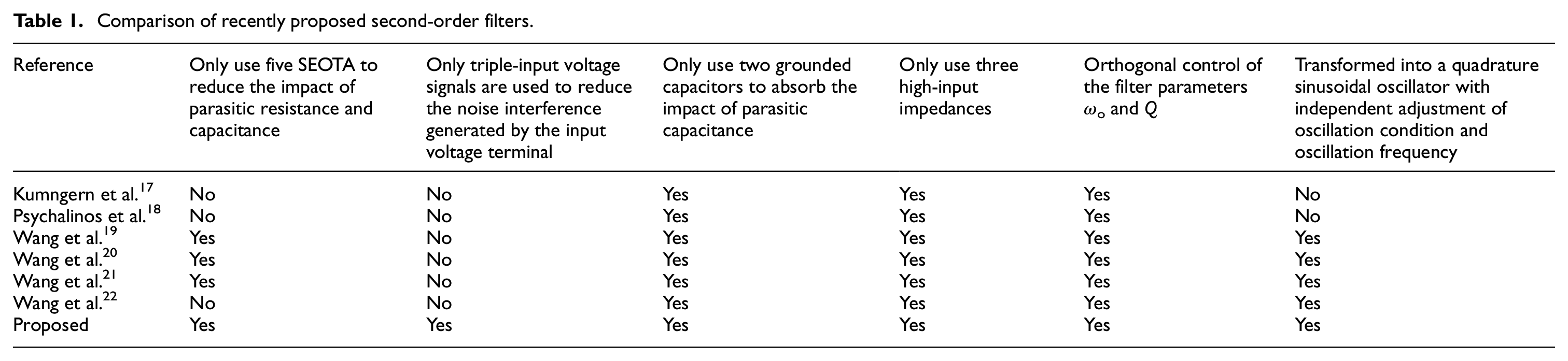
In this study, a new high-input impedance structure with triple inputs and single output for realizing universal VM SEOTA-based second-order filter is proposed. The proposed universal second-order filter architecture uses five SEOTAs and two ground capacitors, which can realize VM second-order NLPF, NHPF, IBPF, NBRF and NAPF voltage responses by appropriately connecting triple-input voltage signals. The proposed universal VM SEOTA-based second-order filter permits orthogonal and electrical controllability of the ωo and Q, and requires no resistors and is suitable to further develop into an IC implementation. The proposed circuit has all advantages in Kumngern et al. 17 and Psychalinos et al. 18 Unlike the reported universal VM SEOTA-based second-order filters in Kumngern et al. 17 and Psychalinos et al., 18 the attractiveness of the proposed universal VM SEOTA-based second-order filter is that it only uses five single-ended OTAs and two grounded capacitors to implement the universal VM SEOTA-based second-order filter and can also be converted into a quadrature oscillator. The advantages of the proposed universal VM SEOTA-based second-order filter are as follows: (i) the proposed filter uses only five SEOTA to reduce the influence of parasitic resistance and capacitance impact at the output terminal, (ii) the proposed filter uses only triple-input voltage signals to reduce the noise interference generated at input voltage terminal and circuit complexity, (iii) the proposed filter uses two grounded capacitors to absorb the influence of parasitic capacitance impact at the output terminal of SEOTA, (iv) the proposed filter has high-input impedance, (v) the proposed filter parameters ωo and Q are orthogonal control, and (vi) the proposed filter can be transformed into an quadrature sinusoidal oscillator with independent adjustable of oscillation condition and oscillation frequency. Table 1 compares the proposed universal VM SEOTA-based second-order filter with previously published researches.17–22 It can be seen that the proposed universal VM SEOTA-based second-order filter can simultaneously achieve all the above imported properties. In addition, filters and oscillators are used in measurement and control system, such as in phase sensitive detection system, 23 wireless sensor network, 24 and the high fidelity 3-way speaker. 25 Compared with the five SEOTAs and two ground capacitors circuits proposed in Wang et al.,19–21 the proposed circuit can realize universal VM second-order NLPF, NHPF, IBPF, NBRF, and NAPF voltage responses by appropriately connecting triple-input voltage signals, which can reduce the noise interference generated at the input voltage terminal and circuit complexity. Compared with the one dual-output OTA, three SEOTAs and two capacitor circuit proposed in Wang et al., 22 the proposed circuit only uses SEOTA active components and does not limit the design of using LT1228 IC. 26 Since the proposed SEOTA-based filter can replace the resistance in other active filter designs, the power consumption of the proposed SEOTA-based filter is lower than other active filters.
Comparison of recently proposed second-order filters.
Proposed universal VM SEOTA-based filter and oscillator
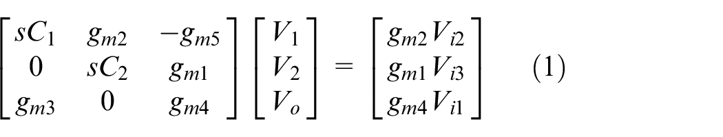
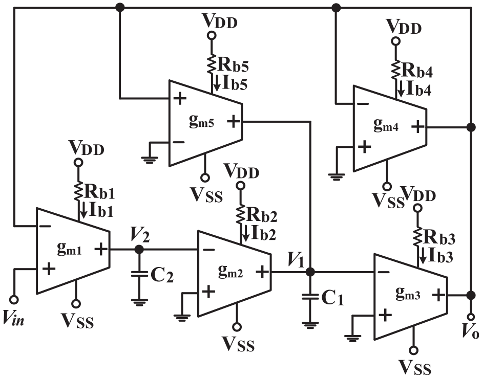
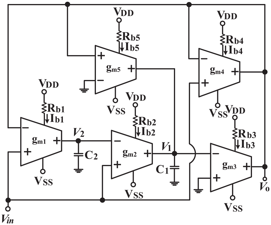
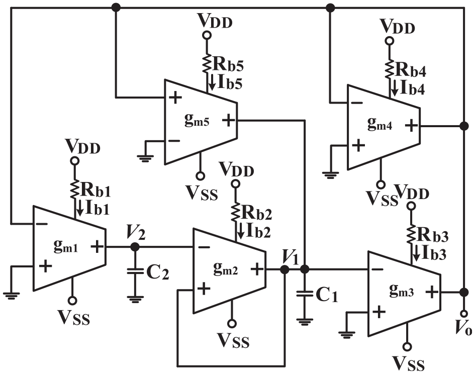
The SEOTA is a differential voltage-controlled current source with trans-conductance gain and its ideal characteristic can be characterized by IO = gm(V+–V−), and its gm can be controlled by external DC Ib signal.17,18 Figure 1 shows the implementation of the universal VM SEOTA-C second-order filter with triple inputs and single output. In Figure 1, it consists of five SEOTA active components and two grounded capacitors, and all input signals are connected to the high impedance input nodes of SEOTA. Hence, the proposed universal VM SEOTA-C second-order filter enjoys the advantage of high-input impedance. The use of only two grounded capacitors and resistorless makes the proposed universal VM SEOTA-C second-order filter suitable for IC implementation. A routine circuit analysis of Figure 1 yields triple inputs and signal output matrix equation as follows.
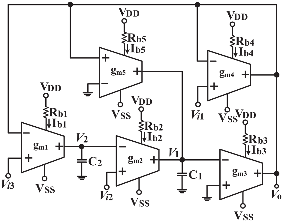
The proposed universal VM SEOTA-C second-order filter with triple inputs and single output.
Based on (1), the universal VM SEOTA-C second-order filter with triple inputs and single output can be realized in (2).
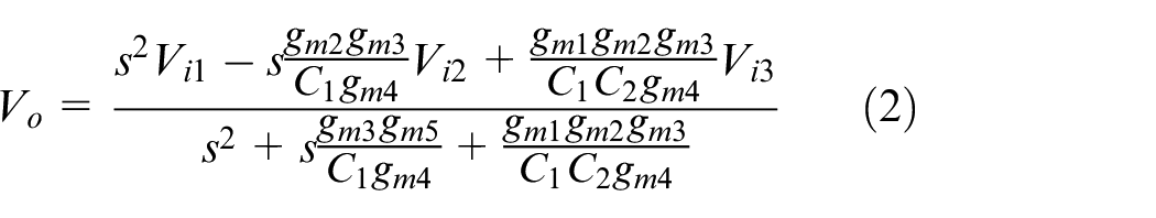
According to the input voltage states of Vi1, Vi2, and Vi3 in the output transfer numerator of (2) and assuming gm2 = gm5, one of the following five filtering transfer functions can be realized:
NLPF: Vi3 = Vin (input signal) and Vi1 = Vi2 = 0 (grounded),
IBPF: Vi2 = Vin (input signal) and Vi1 = Vi3 = 0 (grounded),
NHPF: Vi1 = Vin (input signal) and Vi2 = Vi3 = 0 (grounded),
NBRF: Vi1 = Vi3 = Vin (input signal) and Vi2 = 0 (grounded),
NAPF: Vi1 = Vi2 = Vi3 = Vin (input signal).
Based on (i) to (v), the circuit implementations of NLPF, IBPF, NHPF, NBRF, and NAPF were shown in Figures 2 to 6, respectively.
The circuit implementation of NLPF.
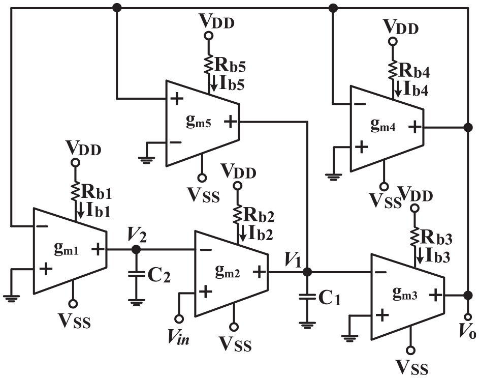
The circuit implementation of IBPF.
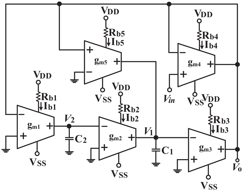
The circuit implementation of NHPF.
The circuit implementation of NBRF.
The circuit implementation of NAPF.
Based on (2), the filter parameters of ωo and Q can be given as follows.
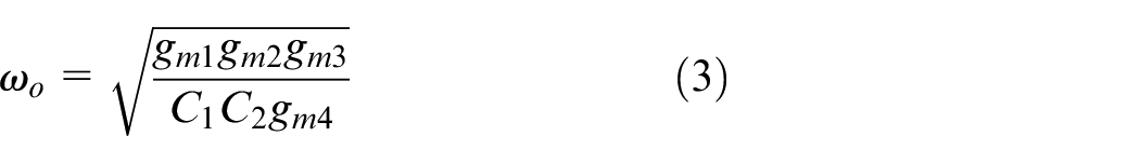
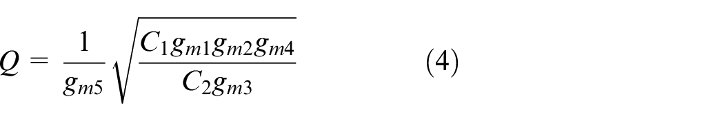
Based on (3) and (4), the Q-value can be electronically by gm5 with affecting the ωo, and therefore the parameters of ωo and Q have orthogonal and electronic controllability.
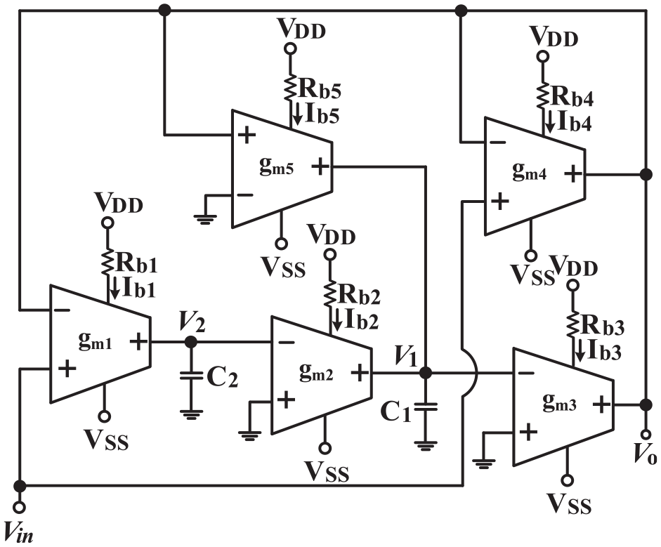
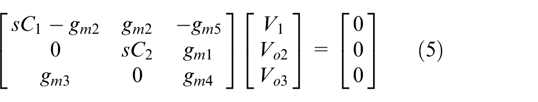
On the other hand, the universal VM SEOTA-C second-order filter of Figure 1 can be converted into a VM SEOTA-C quadrature sinusoidal oscillator by making the input signals Vi1 and Vi3 to grounded and connecting the Vi2 input terminal to V1 terminal of Figure 1. Therefore, a VM SEOTA-C quadrature sinusoidal oscillator with two output sinusoidal voltages is realized in Figure 7. The circuit analysis of the VM SEOTA-C quadrature sinusoidal oscillator of Figure 7 yields a matrix equation as follows.
The proposed VM SEOTA-C quadrature sinusoidal oscillator based on Figure 1.
Based on (5), the characteristic equation of Figure 7 is given by
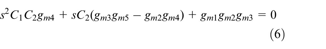
From (6), the condition of oscillator (CO) and the frequency of oscillator (FO) are given by


Based on (7) and (8), the CO can be electronically controlled by gm5 without effecting the FO and the FO can be electronically controlled by gm1 without effecting the CO. Thus, the CO and FO can be electronically and independently controlled. In Figure 7, the relationship between two output voltages Vo2 and Vo3 are related as
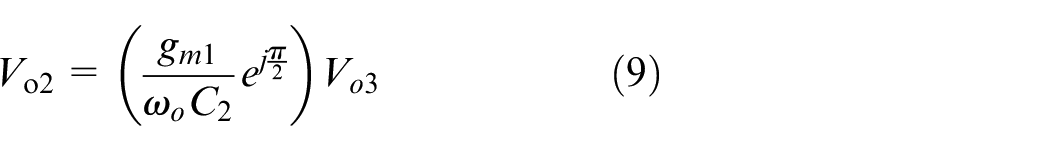
Thus, the proposed VM SEOTA-C quadrature sinusoidal oscillator has two quadrature sinusoidal voltage outputs Vo2 and Vo3. It can be seen that the universal VM SEOTA-C second-order filter of Figure 1 can be converted into a VM SEOTA-C quadrature sinusoidal oscillator with two output sinusoidal voltages.
Simulation and experimental results
The proposed universal VM SEOTA-C second-order filter and VM SEOTA-C quadrature sinusoidal oscillator were simulated and measured by Cadence OrCAD PSpice version 17.2 software, Tektronix DPO 2048B, keysight E5061B-3L5 network analyzer and Keysight-Agilent N9000A CXA signal analyzer. The commercially available LT1228 ICs 26 were chosen for realizing universal VM SEOTA-C second-order filter and VM SEOTA-C quadrature sinusoidal oscillator. According to the datasheet, 26 the gm-value of LT1228 is equal to 10 times the value of DC Ib (i.e. gm = 10Ib). The formula for DC Ib is Ib = (VDD– VSS−2VBE)/Rb, where VDD is positive power supply voltage, VSS is negative power supply voltage, VBE is a bias voltage of bipolar junction transistor, and Rb is bias control resistor used to obtain DC Ib. Figures 8 to 12 show the responses of the gain-frequency and phase-frequency results for the universal second-order NLPF, IBPF, NHPF, NBRF and NAPF responses by selecting triple-input terminals. In Figures 8 to 12, the proposed universal VM SEOTA-C second-order filter is designed for center frequency of 265.26 kHz by choosing C1 = C2 = 1.8 nF and all gm-values are set as 3 mA/V, so that Ib = 300 μA. These results confirm to the previous theoretical analyses. Because the OTA has parasitic resistance and capacitance at the voltage input terminal and the current output terminal, this can explain why the simulation and measurement frequency in Figures 8 to 12 will deviate when the frequency exceeds 1 MHz. Figure 13 shows the time-domain of the IBPF voltage response to test the input dynamic range of the universal VM SEOTA-C second-order filter, where all trans-conductance values as 3 mS, and C1 = C2 = 1.8 nF. In Figure 13, the simulation is repeated for a sinusoidal input signal of fo = 265.26 kHz. Figure 14 shows the two-tone testing of the IBPF voltage response through intermodulation characterization. In Figure 14, two closely spaced tones, f1 = 264 kHz and f2 = 266 kHz, are used with equal input amplitudes of 35 mVp. The measured value of the third-order intermodulation distortion (IMD) point is around −29.72 dBc. The supply voltages were ±15 V. The simulated and measured power dissipation of the VM SEOTA-C second-order filter are 0.86 and 1.35 W, respectively.
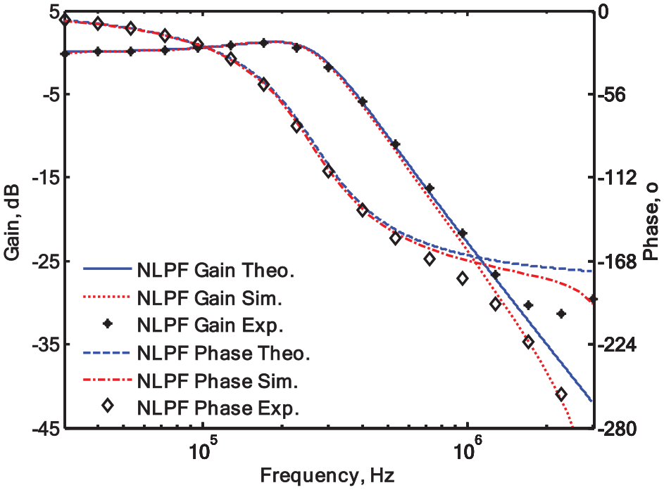
Experimental, simulated and theoretical values of non-inverting low-pass filtering function.
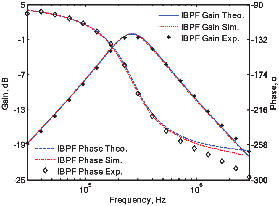
Experimental, simulated and theoretical values of inverting band-pass filtering function.
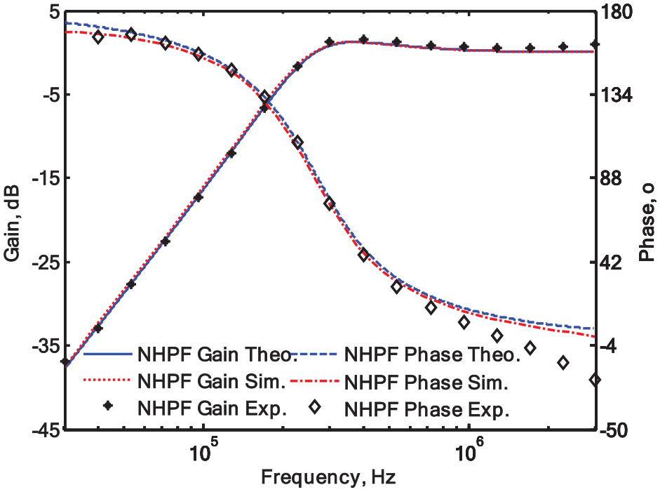
Experimental, simulated and theoretical values of non-inverting high-pass filtering function.
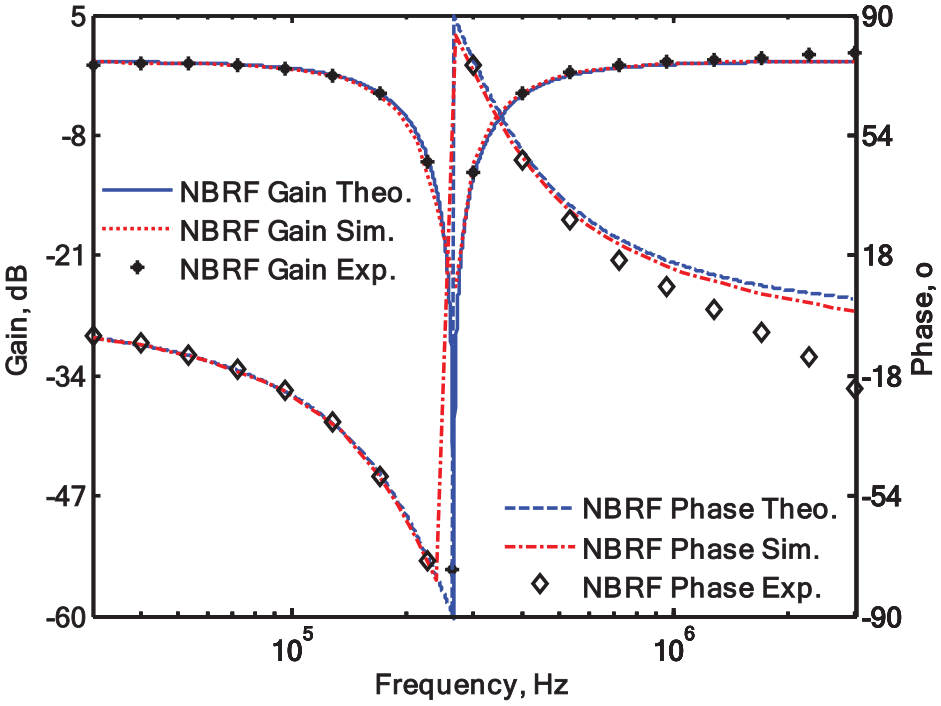
Experimental, simulated and theoretical values of non-inverting band-reject filtering function.
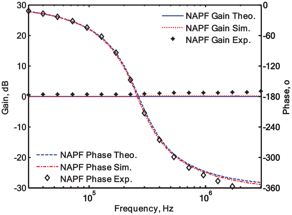
Experimental, simulated and theoretical values of non-inverting all-pass filtering function.
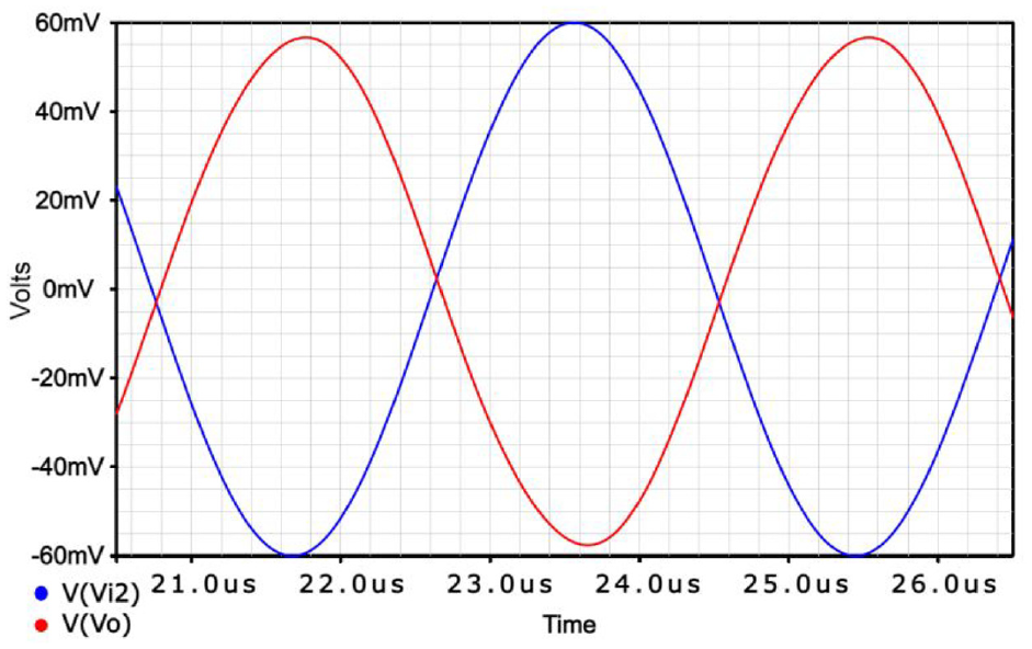
Input (blue line) and output (red line) waveforms of the inverting band-pass filtering function time-domain results.
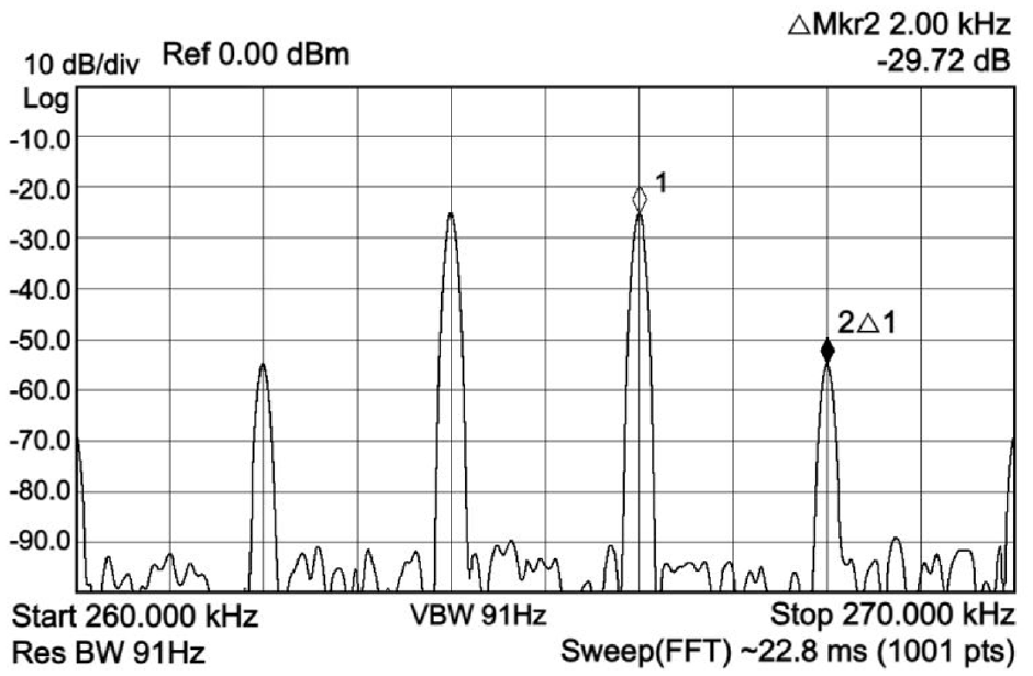
The inverting band-pass response output spectrum for a two-tone intermodulation distortion test.
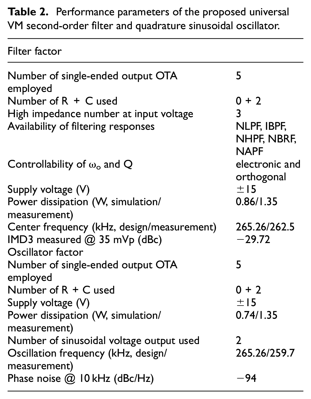
In order to obtain the VM SEOTA-C quadrature sinusoidal output waveform when the oscillation frequency fo is equal to 265.26 kHz in Figure 7, C and C12 are set to 1.8 nF, and all trans-conductance values are 3 mS. However, gm5 is equal to 2.91 mS, which is less than gm4 to ensure that the oscillation starts. As shown in Figure 15, the measured oscillation frequency is 259.7 kHz, which is very close to the theoretical value. Figure 16 shows the experimental results of the Lissajous pattern output by Vo2 and Vo3 in Figure 15. Figure 17 shows the use of Agilent’s phase noise measurement solution to calculate phase noise. The phase noise of the proposed VM SEOTA-based quadrature sinusoidal oscillator is lower than −94 dBc/Hz (at a 10 kHz offset). The simulated and measured power dissipation of the VM quadrature oscillator are 0.74 W and 1.35 W, respectively. Table 2 summarizes the performance of the proposed VM SEOTA-C second-order filter and quadrature sinusoidal oscillator.
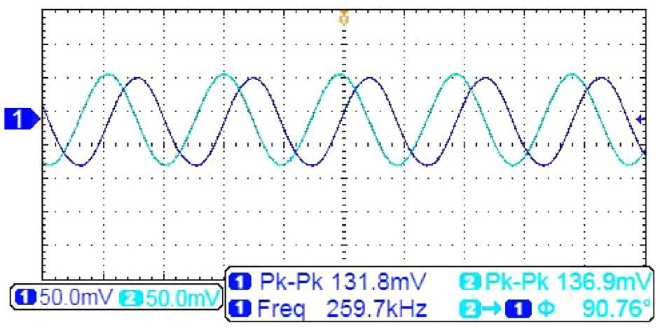
The time-domain experimental results of the steady-state quadrature sinusoidal outputs Vo2 (channel 1) and Vo3 (channel 2).
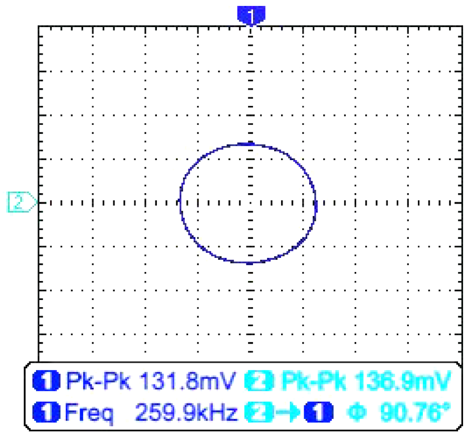
The Lissajous pattern of Vo2 and Vo3 output voltage signals in Figure 15.
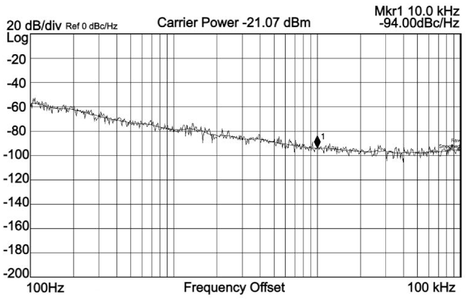
The measured phase noise of the proposed VM SEOTA-based quadrature sinusoidal oscillator.
Performance parameters of the proposed universal VM second-order filter and quadrature sinusoidal oscillator.
Conclusions
This paper proposed a new high-input impedance electronically tunable universal VM SEOTA-C second-order filter with triple inputs and single output. The proposed filter uses five SEOTAs and two grounded capacitors, which is suitable for IC implementation. It has high-input impedance suitable for cascading input terminal, and exhibits orthogonal and electrical controllability of the filter parameters ωo and Q. The proposed circuit provides universal VM second-order NLPF, NHPF, NBRF, NAPF and IBPF voltage responses by appropriately connecting triple-input voltage signals, and has low sensitivity performance. By slightly modifying the proposed VM universal SEOTA-C second-order filter configuration, the VM SEOTA-C quadrature sinusoidal oscillator with two output sinusoidal voltages can be implemented. The FO and CO of the quadrature sinusoidal oscillator can be independently and electronically controlled by adjusting the bias current of two SEOTAs. The simulation and measurement results confirm the VM SEOTA-C second-order filter and oscillator theoretical analysis. Since the proposed SEOTA-based filter can replace the resistance in other active filter designs, the power consumption of the proposed SEOTA-based filter is lower than other active filters.
Footnotes
Declaration of conflicting interests
The author(s) declared no potential conflicts of interest with respect to the research, authorship, and/or publication of this article.
Funding
The author(s) received no financial support for the research, authorship, and/or publication of this article.