
Abstract
This paper presents a robust control methodology for a microelectromechanical systems gyroscope, which named time-varying disturbance observer based on regulating boundary layer thickness sliding mode control First, the micro electromechanical systems gyroscope mathematical model has been analyzed. Second, time-varying disturbance observer (T-V DOBs) was constructed for observing the unwanted signals from inside and outside of the system, which is well known as disturbance and uncertainty estimation. The time-varying disturbance observer has been constructed based on the basic nonlinear disturbance observer, the estimated disturbance has been used to compensate the outside disturbance and inside uncertainty. Third, the proportional integral derivative sliding mode surface was used to construct the equivalent control, afterward the switching control value of sliding mode control was selected following the regulating boundary layer thickness by using the fuzzy logic control to construct the switching boundary thickness. The simulation results has been archived by using MATLAB software. The chattering was significant goes to zero, and disturbance was mostly rejected. The convergence condition was proved based on the Lyapunov law.
Keywords
Introduction
Taking the advantages of small size, low usage energy, low-cost, and easy to install, MEMS system has been widely attracted many engineering fields as automotive industry, navigation. 1 Besides there, the MEMS gyroscope has some disadvantages as temperature changes, parameters varying, and disturbance effects. To solve these problems, many previous published papers has investigated with the MEMS gyroscope as Feng and Fei 2 proposed the supper-twisting sliding mode control for this system based on the radial basic function (RBF) neural network, where the RBF was used to estimate the unknown disturbance and uncertainty. Xu et al. 3 proposed a composite neural network learning based nonsingular terminal sliding mode control for MEMS system. Rahmani et al. 4 proposed a new hybrid robust control of MEMS gyroscope, those paper given tracking error values are still high. Chen and Fei 5 proposed fractional order adaptive sliding mode control method for micro gyroscope. Fei et al. 6 proposed an adaptive nonsingular terminal sliding mode control for MEMS system. The reaching time of their papers were shown not very good. Zhang et al. 7 proposed the SMC composite learning to MEMS, their paper distance tracking error was shown not very small. The springs on the MEMS was considered as the nonlinear springs. Fang et al. 8 proposed an adaptive control for the MEMS system by considering the system is a Takagi-Sugano model. According to the best author knowledge, no previous published paper has investigated to time-varying disturbance observer for the MEMS system, the time varying disturbance means the first derivative of disturbance is different to zero. There is Bagher et al. 9 proposed the disturbance observer for MEMS system, the lumped uncertainty was needed assumption be bounded. In fact, the disturbance and uncertainty variation rates are unknown. These terms are very difficult rejected by apply the basic nonlinear with an assumption the first derivative of disturbance equaled to zero. Since this weak point, this paper proposed a new technology for estimating the unknown disturbance and uncertainty, if the disturbance and uncertainty exist first derivative value is different to zero.
The nonlinear disturbance observer is a special case of unknown input observer. It was introduced in the 1980s by Ohishi. 10 Since the time the nonlinear disturbance was introduced, the application of this method has been applied into many areas as Chen 11 presented a general nonlinear disturbance observer for nonlinear system. Chen et al. 12 proposed disturbance observer for the ball mill grinding circuits based on the multi-variable control method. Recent years, the nonlinear disturbance observer is still very hot topic for industrial application. Some published papers as Tsai et al., 13 Mohammadi et al., 14 Liu et al. 15 Mohammadi et al. 16 and Huang et al. 17 Some advanced disturbance and uncertainty rejection were investigated as Pan et al. 18 proposed the adaptive tracking control for nonlinear suspension system. Those paper proposed an uncertainty estimation, which fulfilled the Lyapunov to obtain the disturbance and uncertainty values. On the same problem of suspension system, Pan et al. 19,20 proposed a finite disturbance observer to compensate the disturbance and uncertainty for the system and adaptive fault-tolerant compensation control, which took advantage of adaptive state feedback to compensate actuator faults. Those paper achieved good results, but very difficult to obtain exactly disturbance and uncertainty compensation values. Basically, a specific disturbance observer can obtain the disturbance and uncertainty rejection precisely. However, disturbance observer in paper 11 somehow needs an assumption that the first derivative disturbance is equaled to zero. In fact, the knowledge of disturbances effect to the physical system are unknown. The convergence rate of disturbance estimation of paper 11 depends on the frequency of the disturbance, which means low frequency disturbance can easier to be obtained but high frequency disturbance does not. Since this weaken point, this paper used the previous published nonlinear disturbance observer concepts 11 to construct the new time-varying disturbance observer, the newly estimated disturbance was used to compensate the disturbance and uncertainty of the system. Previous paper’ disturbance observer mathematical model is subset of this paper disturbance observer. The compensation leads system to archive better performances, where the distance tracking error values are quite small, steady-state very stable, and system perturbations were completely rejected. Basically, the compensator needs working based on a background controller. This paper proposed a new sliding mode controller to control the MEMS gyroscope states converge and stable on the predefined proportional integral derivative sliding mode surface, the saturation with a flexible boundary layer thickness took place of the sign function. The boundary layer thicknesses were regulated by the saturation of fuzzy outputs.
SMC is a nonlinear control method, which consists of switching control and equivalent control. These control values are used to force system state tends to convergence and stable on the predefined manifold, respectively. The sliding mode control was revealed in the mid of the 1950s 21 SMC is one kind of variable structure control. 22 The sliding mode control has a shortcoming of chattering phenomenon, 23 which occurs from the boundary layer thickness and switching control gain. The witching control gain is larger leads the speed of the convergence is faster, vice visa. The convergence speed is main reason of chattering problem. Many papers has dealt with this problem as Su, 24 Fang et al. 25 Saghafinia et al. 26 and Igor. 27 This paper proposed a proportional integral derivative of tracking error values to design the sliding mode surface. To regulate the boundary layer thickness, a fuzzy logic control with single input and single output has been implemented to find an optimal boundary values.
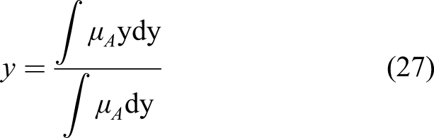
Fuzzy logic control is heuristic approach where the fuzzification, inference engine, and defuzzification are included in the fuzzy logic control process. 28 The fuzzification uses the input to determine the fuzzy sets, the inference engine takes in charge of the determination input variables and fuzzy rules. Finally, defuzzification takes in charge of conversion for the fuzzy crisp of inference engine to output variables. This paper used the Mamdani fuzzy logic control with single input and single output if-then rules, due to its precious properties to nonlinear control design, intuitive for designer. This is a simple fuzzy control method, easy to covert the mathematical ideas to fuzzy rules, and can apply for single input single output system.
Motivated by previous discussion for disturbance observer and sliding mode control, this paper focuses on design a new disturbance observer based on sliding mode controller for MEMS system. A flexible boundary layer thickness of saturation function in the switching control value of the sliding mode control was proposed. The changing of the distance tracking error can be decreased by a variable boundary layer value. Not like conventional sliding mode control with a fixed boundary value. The variable thickness can be applied to the MEMS system to get better outcome. Which could be understood as an adaptive ability of the saturation function. Otherwise, under the harsh working environments the MEMS system should equipped more disturbance observer to cancel to disturbance from outside and system parameters’ variation from inside of the system. A new disturbance observer was introduced to the MEMS system to obtain the goals.
Contributions and novelty of this paper are as following. 1. The time-vary disturbance observer was proposed to the MEMS system, where the unknown disturbance was deleted completely with an exponential convergent speed. The originality of the proposed method is no need assumption for the first derivative disturbance goes to zero when time going to infinity. 2. A proportion-integral-derivative sliding mode surface was designed to control MEMS system with the flexible boundary layer thickness of saturation function. The chattering of the system was cancelled mostly with this new control technique. 3. The conditions of stability was given following the Lyapunov law. There are conditions of boundary layer thickness sliding mode control gains are clearly given.
The paper is organized as follows; (i) Introduction was given in the first part. (ii) The MEMS mathematical model is given in section 2, which together with problem formulation. (iii) Proposed methodology will be given in the third section. (iv) Illustrative example is located in the fourth section of the paper. (v) The conclusion is last given in fifth section.
Mathematical modeling of MEMS Gyroscope and problem formulation
Following Feng and Fei
2
the system mathematical model was given as following equation
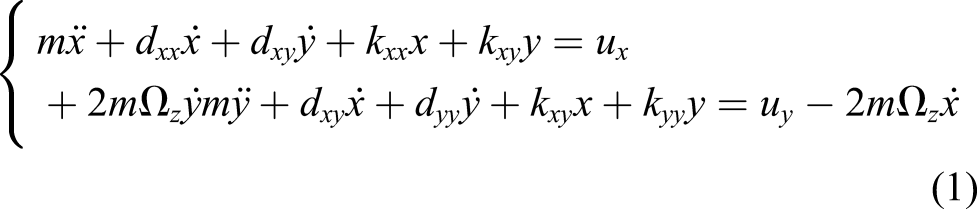
By grouping the equation (2) to general equation as

In fact, the system mathematical could be described as the following equation


Disturbance and uncertainty of MEMS system needs be bounded as The assumption 1 is given differ with a few previous papers,
9,11,14
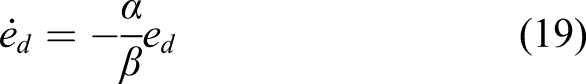
those papers assumed that the first derivative of disturbance go to zero when time going to infinity. The system in equation (4) can be written as The geometry structure of the MEMS gyroscope can be shown in the following Figure 1 below. The previous published papers needed an assumption that the lump uncertainty and disturbance and its first derivative values need be bounded and equal to zero, respectively. In fact, if the perturbations of the system is time varying term, it leads the first derivative these perturbations is different to zero. To solve the limitation of previous nonlinear disturbance observer, this paper proposed new disturbance observer for the MEMS gyroscope by using the basic nonlinear disturbance observer proposed by Chen
11
to construct the new feedback disturbance term, this performance will be appeared in next section. The basic nonlinear disturbance observer can be considered as a subset of our new disturbance observer. Basically, the disturbance observer is well known as the black box. Which uses the control input and system output signals to compensate the perturbation values. Since this point, the control design is request to meet the goals. To construct the controller for the MEMS system, this paper used the sliding mode control with a proportional-integral-derivative sliding mode surface to find the equivalent control value and the sliding mode surface. Sliding mode control are well known consists of equivalent control and switching control. The switching control could be consider as the discontinuous control value. Conventional sliding mode control uses sign function to repent the idea. Some recently papers used the saturation function to get better result of chattering cancellation. The saturation somehow well-known as a fixed boundary layer thickness, where the chattering is still existed definitely. The switching control gain is main portion of chattering source. To solve the problem of chattering, the adaptive switching gain or adaptive boundary layer thickness could be introduced perfectly. The adaptive law can build by applying the mathematical model or support of fuzzy logic control. In this paper the boundary layer thickness was regulated by a fuzzy logic control.

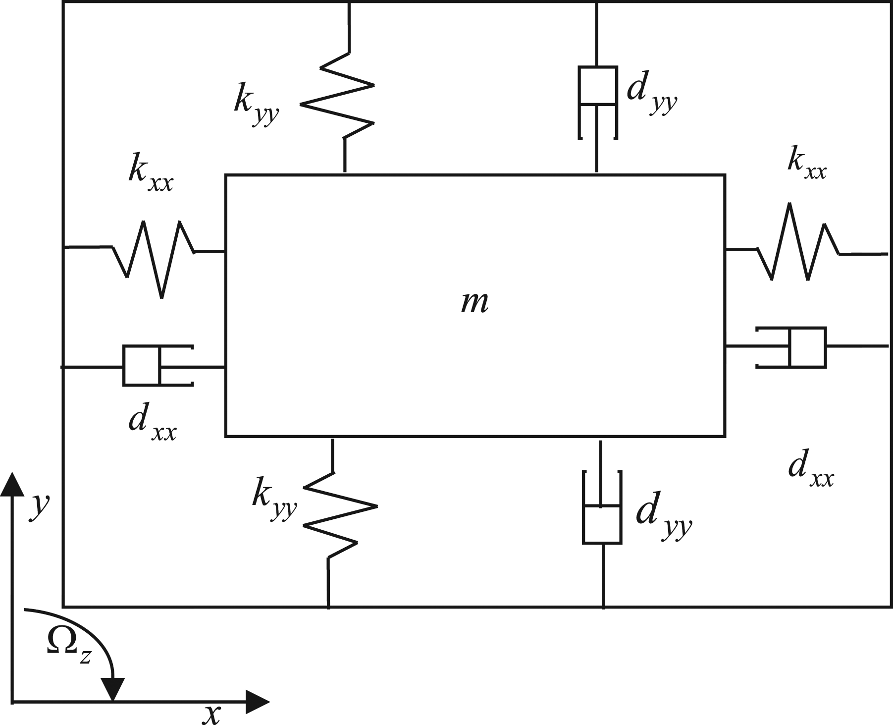
MEMS geometry shape.
Proposed approach
Time-varying disturbance observer
This paper used the basic nonlinear disturbance was proposed by Chen
11
to construct a new time-varying disturbance observer. By referring

Taking the derivative of the equation (9) with both side yields
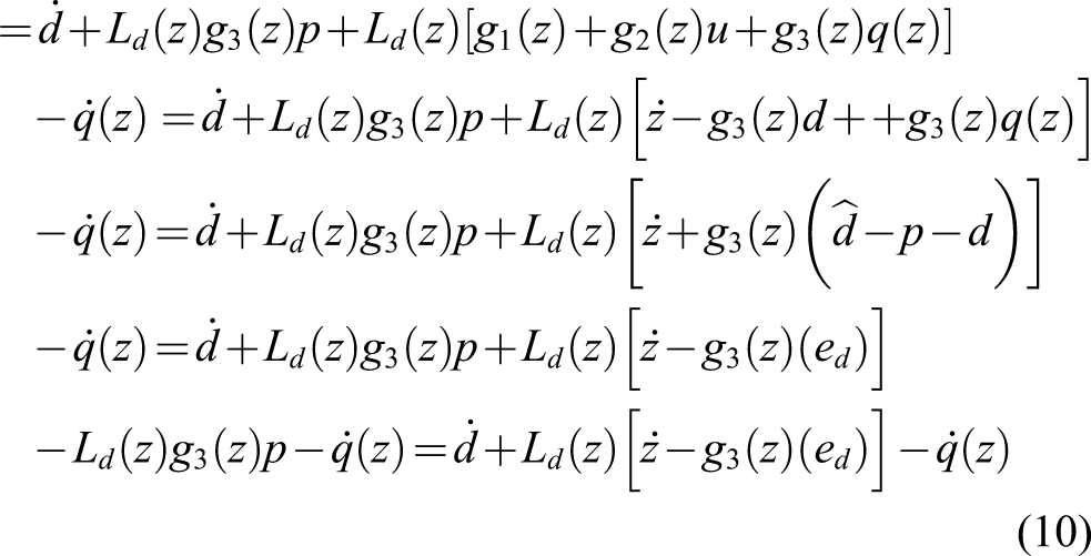
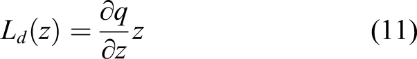
By applying the nonlinear disturbance gain

The equation (10) can be modified as following

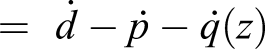
Many previous published papers assumed that the first derivative disturbance is somehow equaled to zero. This paper proposed a new method to deal with the time-varying disturbance where first derivative disturbance value is unknown. The proposed observer is presented as following equation (14) below

From the equation (8)
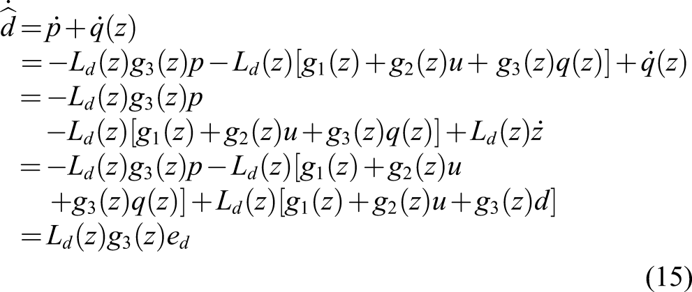
By applying the

By subtracting both side of above equation (16) by the first derivative of disturbance value yields


Regulating boundary layer thickness sliding mode control
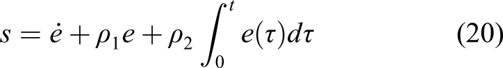
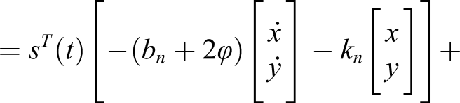
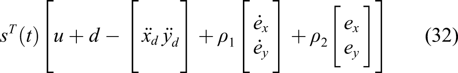
To force the system states stay and converge to the desired manifold, this paper proposed the sliding mode control method with a regulating boundary layer thickness in the switching control part. By referring the distance tracking error values as

Substituting equations (5) in to (21) leads to

By ignoring the effects of disturbance and uncertainty to calculate the equivalent control value

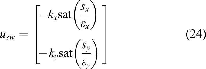
The switching control value is proposed as following equation
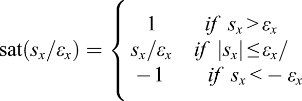
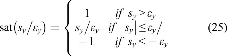
As Gandikota and Das, 29 Giap and Huang 30 mentioned the effectiveness of the boundary layer thickness, therein the boundary layer thickness was regulated by regulating the control value. This paper proposed a new term of regulating the boundary layer, which was guaranteed by fuzzy logic control.
Fuzzy logic control
The general form of the If-Then fuzzy logic control was represented as following

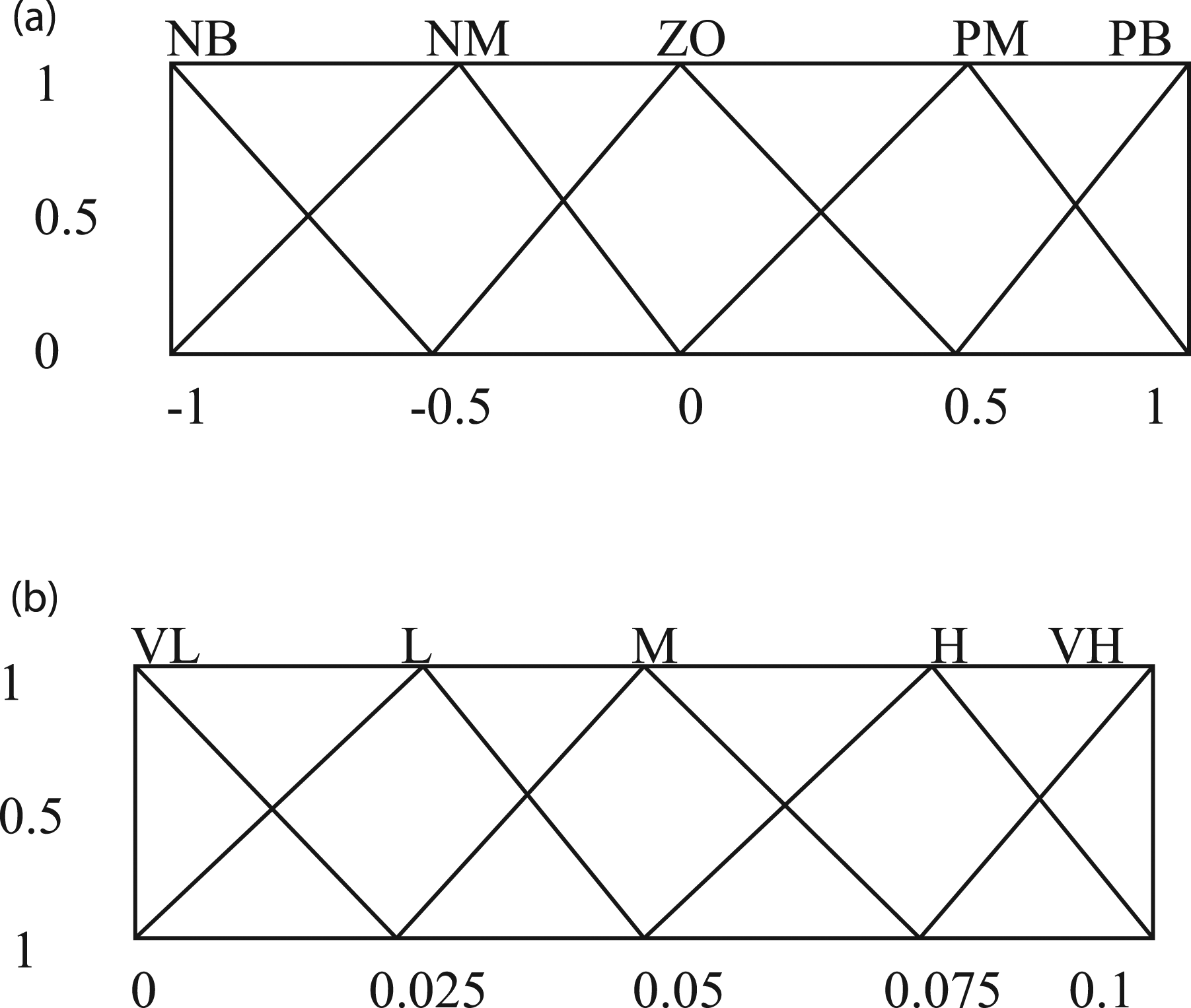
The proposed fuzzy rules for boundary layer thickness of x-axis as following.
If
If
If
If
The fuzzy rules are shown in Figure 2 below. Fuzzy logic inputs and output membership functions: (a) membership function for inputs 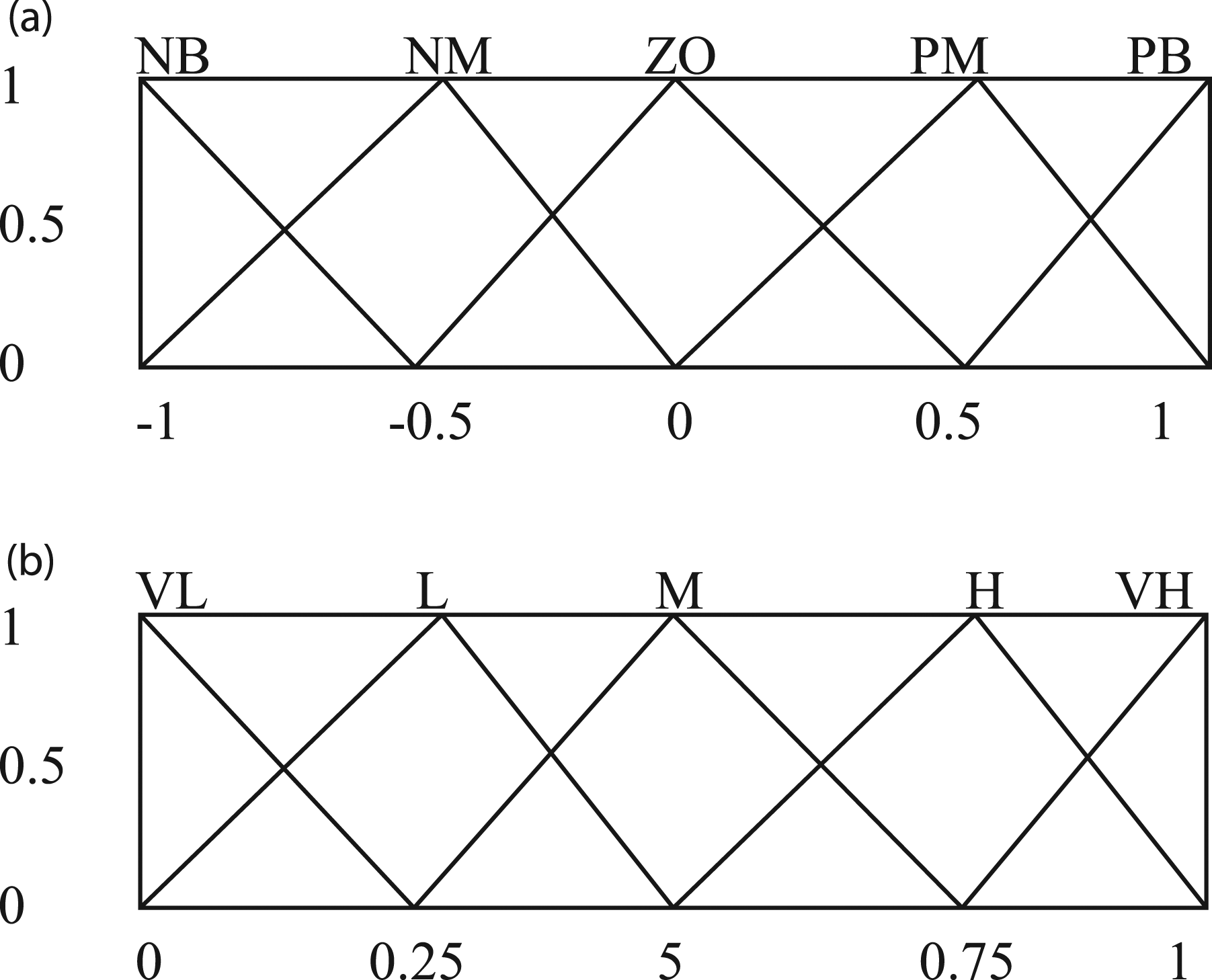
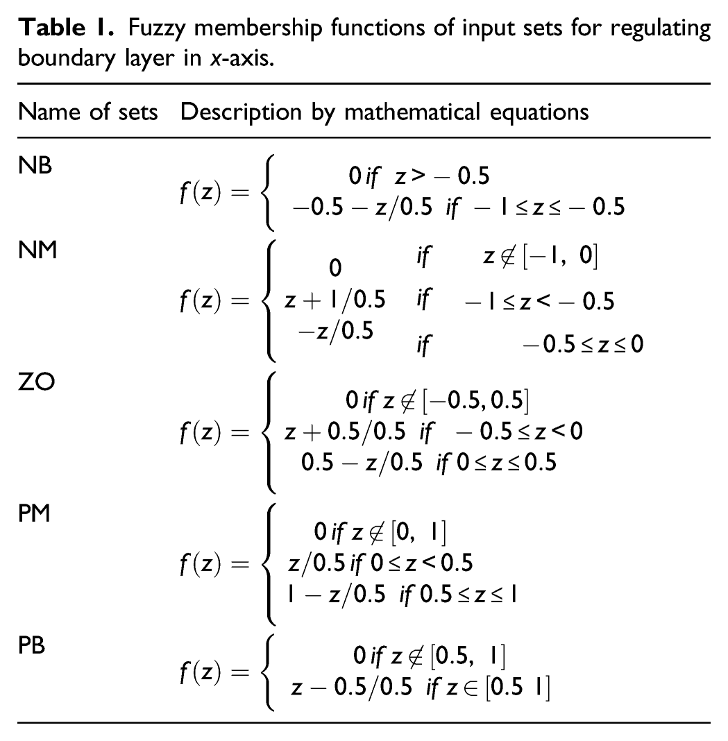
Fuzzy membership functions of input sets for regulating boundary layer in x-axis.
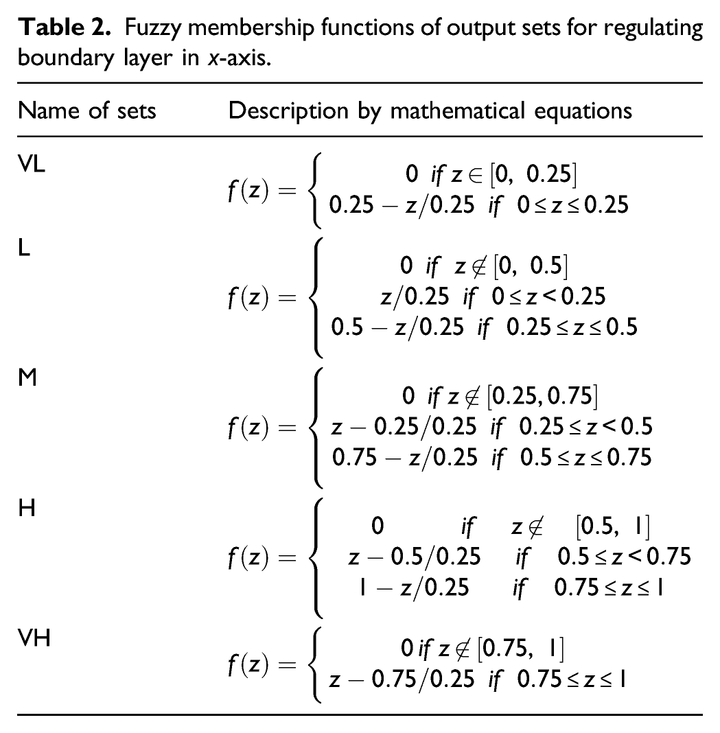
Fuzzy membership functions of output sets for regulating boundary layer in x-axis.
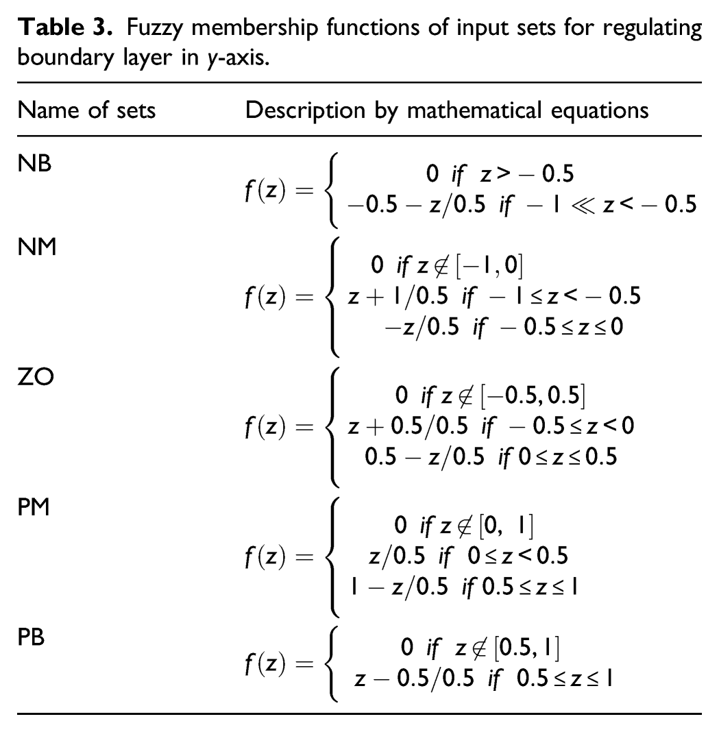
Fuzzy membership functions of input sets for regulating boundary layer in y-axis.
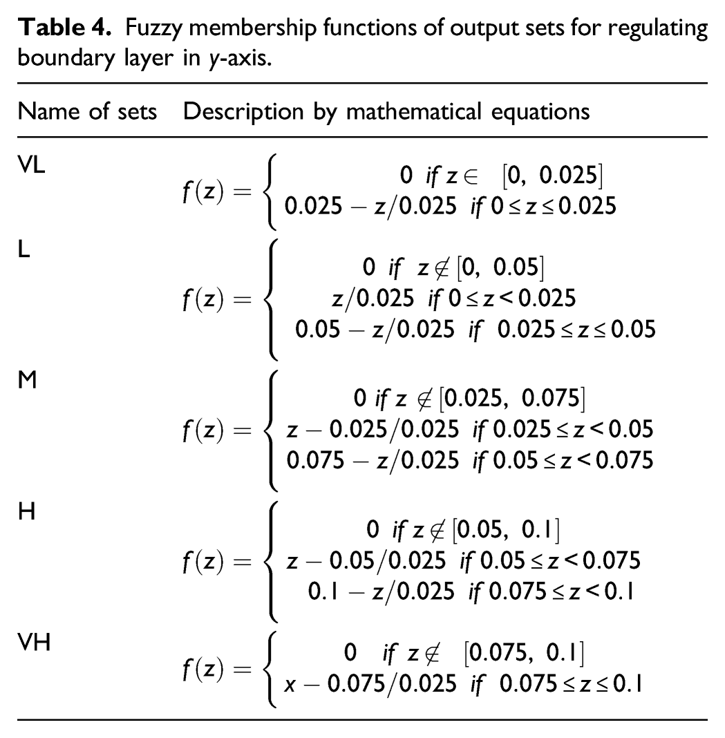
Fuzzy membership functions of output sets for regulating boundary layer in y-axis.
The fuzzy rules for the boundary layer thickness in the y-axis are as following.
If
If
If
If
If
The fuzzy rules can represented as following Figure 3 below.where z term is used to represent the membership functions’ value. This paper proposed the regulating boundary layer thickness sliding mode control with the new switching law as Fuzzy logic inputs and output membership functions: (a) membership function for inputs 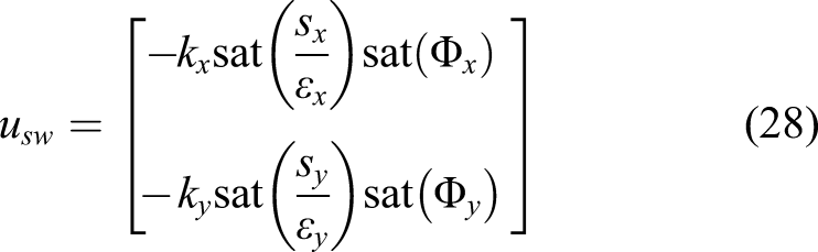
The stability is given in the next section.
Stability condition
The stability candidate was selected as following equation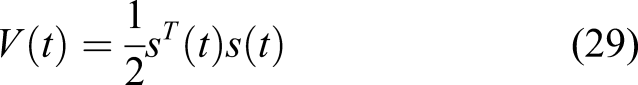
Taking derivative the stability function yields
The sliding mode control is vector values, then equation (30) can be written as follows
Combining the equations (23), (24) and (32) leads to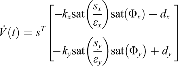
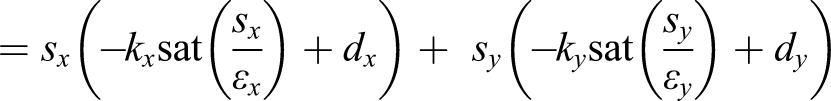

The inequality. (33) is satisfied when
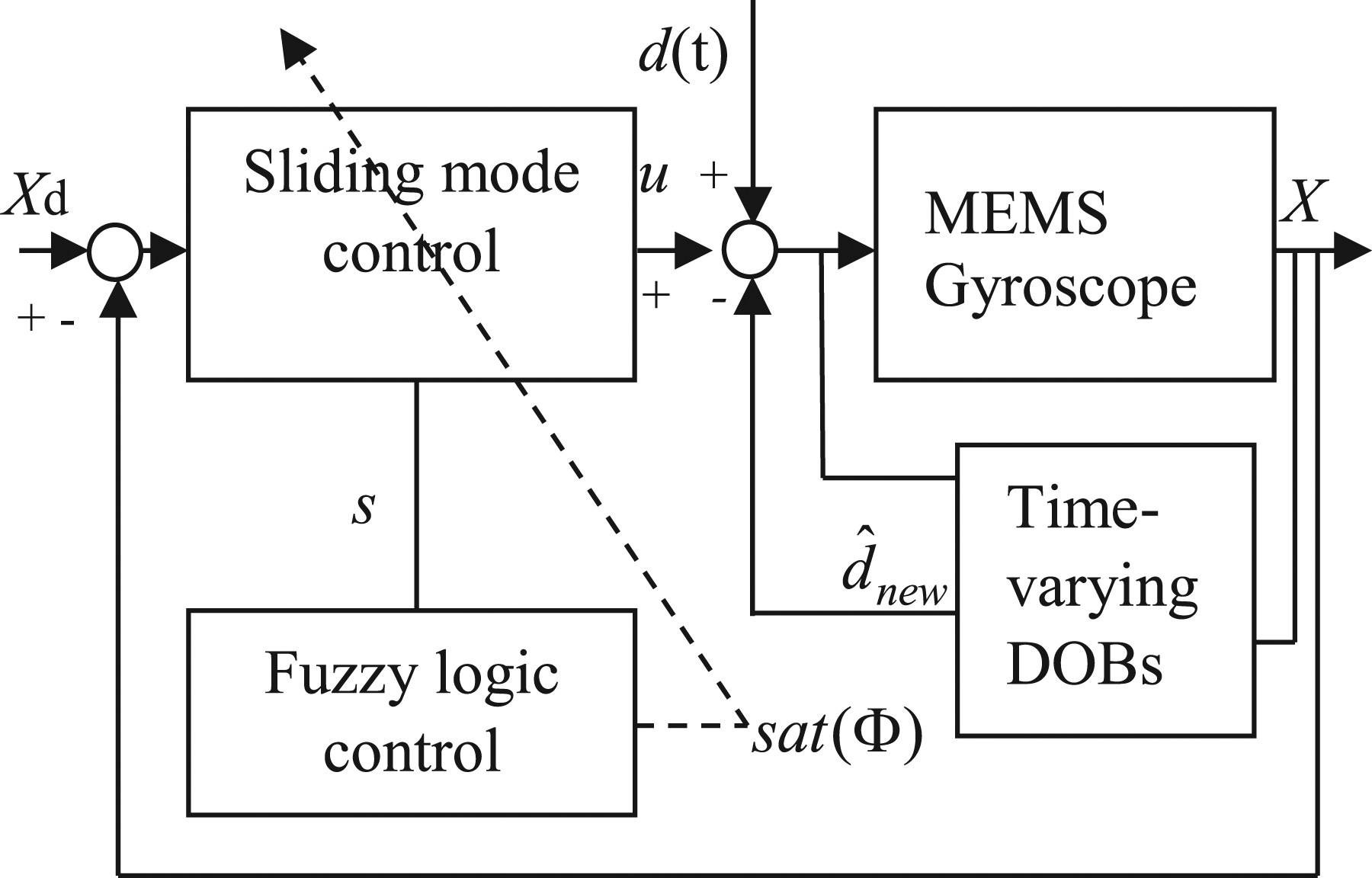
By combining the time varying disturbance observer into the control system, the condition of switching gain slightly flexible as Proposed control system.
The system parameters are as follows:
An illustrative example
This section presents three kinds of control method to emphasize that the proposed method is effected to the disturbance and uncertainty also sensitive to the chattering value rejection.
The first case is named proportional integral derivative sliding mode control, where the tested disturbance to the system strongly effected to the performance of the distance tracking response signals. In this scenario, the controller has been constructed simply by sliding mode control, where a boundary layer thickness was predefined constantly.
The second case is given with a constructed controller in the first case with same parameters, which named time varying disturbance observer based on sliding mode control system. In this scenario, the effected disturbance and uncertainty from outside and inside of the system mostly rejected by a time varying disturbance observer. However, the chattering of the system still exist due to the sliding mode boundary layer thickness was selected by a fixed constant. To solve the problem of chatting value for MEMS system, the boundary layer thickness of sliding mode control can be chose by a regulating value.
The third case is given with the fully controller, where combination of case 2 and two fuzzy logic control in section three.3 are executed. The fuzzy logic controllers were applied to adapt the change of chattering effects.
All cases were tested with same controller parameters and disturbance values where
Case 1The system control without using time varying disturbance observer disturbance observer and the boundary layer of sliding mode control was chosen as a fixed value. The control input is shown as following equation In this case the disturbance effect to the system is maintained, the given results are as following Figure 5 below.
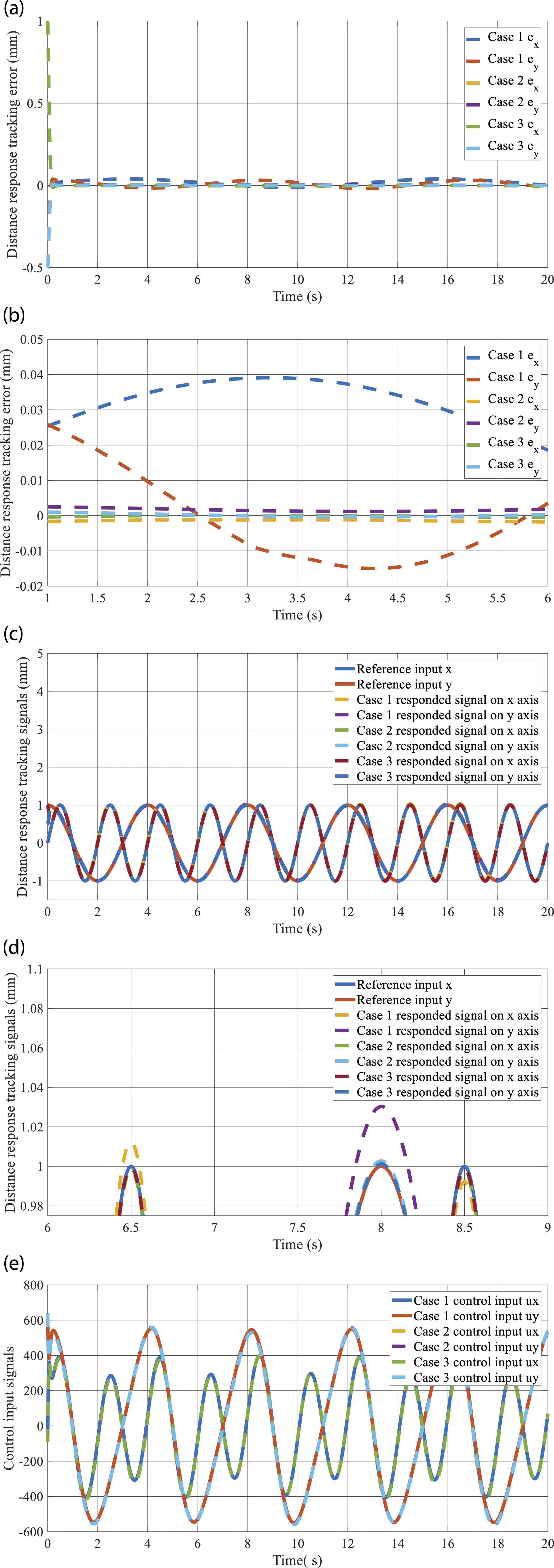
Proposed control method output signals of case 1, case 2 and case 3:
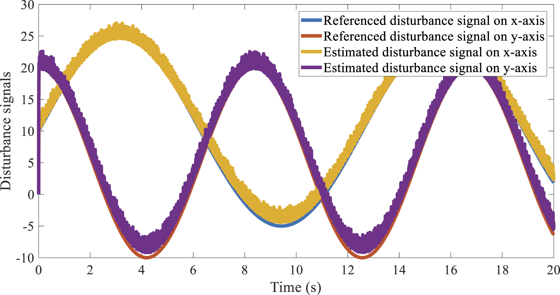
The control signal of this case is calculating by equation (35) minus the estimated disturbance value, and it could be shown as follows Effects of the disturbance and uncertainty values were cancelled completely. The estimated disturbance and uncertainty values are shown on the Figure 6 below.
This section presents all power full of the time-varying disturbance observer based on sliding mode control for MEMS system. The control signal value is given as follows The given results of three cases are shown in the same figure for easy to do analysis. In the first figure, the distance tracking error values were given. The next following figure is given the signal from 1 to 6 s to get more precise comprehension. Subsequently, the distance tracking responded signals, control input signal and disturbance responses are given. The given results are shown as following.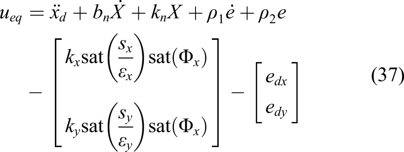
distance tracking error values are
Case 2distance tracking error values are
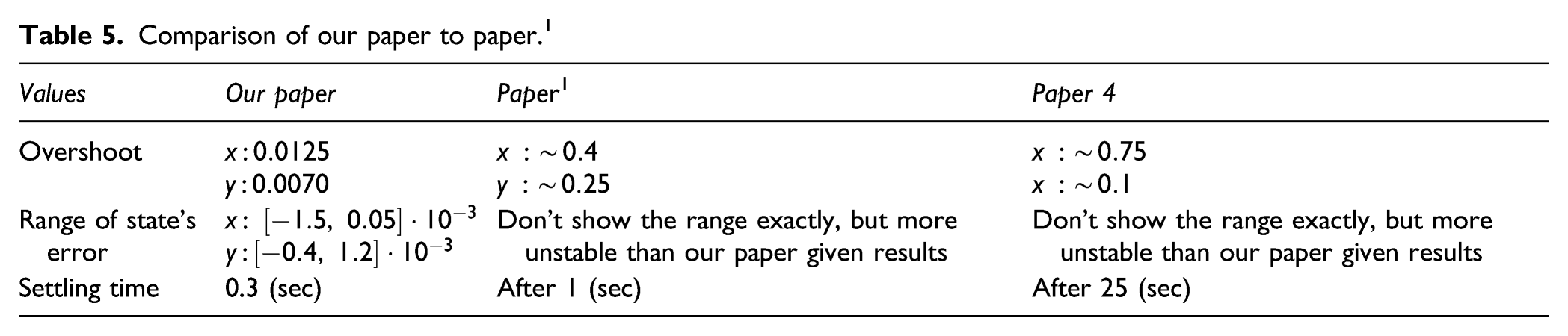
Case 3of study distance tracking error values are The results in Figure 5 are aimed to show that the proposed control method good at tracking the time varying input trajectories and very powerful at rejecting the time-varying disturbance values. More details, the third case reused to emphasize the effectiveness of the regulating boundary layer thickness sliding mode control. The Figure 6 below show the output distance tracking values of the x and y axis with the second case by using fully time varying disturbance observer and regulating boundary layer thickness sliding mode control, and the other case without using the regulating boundary layer thickness. The results are shown as following. By using the regulating boundary layer thickness leads system outputs are better the case of using fixed boundary layer thickness. The reaching times are shorter, steady-states are smaller and stable. The time-varying disturbance observer based on regulating boundary layer thickness sliding mode control can be applied to control many physical system as long as the requirement of system mathematical model is fulfilled as equation (6). There are many papers dealt with control of MEMS. To show advantages and effectiveness of the proposed time-varying disturbance observer based regulating boundary layer thickness sliding mode control to MEMS, this section show the comparison of our proposed method achievements to paper1 and 4. The comparisons are shown in following Table 5 below. The range of state’s error in paper1 and 4 were not shown. However, it were show by plot on Figure 6 of paper
1
and Figure
7
of paper
4
and these outcome can be found on the Figure 7(a) of our paper. Since this comparisons, the proposed time-varying disturbance observer based regulating boundary layer thickness sliding mode control was proposed suitably for MEMS. It achieved good tracking performances.
Comparison of our paper to paper. 1
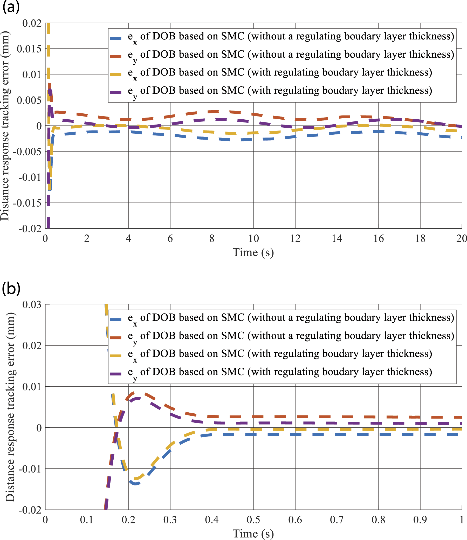
The distance tracking error values of case 2 by using and without using the regulating boundary layer thickness, (a) the distance tracking error values in the first 20(s), (b) the distance tracking error by zooming in the first 1(s).
Conclusion
The control method named time-varying disturbance observer based regulating boundary layer thickness sliding mode control was perfectly constructed for MEMS gyroscope. The archived distance tracking error values completely closed to zero. The disturbances were mostly rejected by a time-varying disturbance observer, which lead the disturbance errors were exponentially converged to zero. The regulating boundary layer thickness was shown effectively for constructing the proportional integral derivative sliding mode control. This is a suggestion for our future work, where the nonlinear spring model of the MEMS system can be considered. Next our’ research will be a control design for Takagi-Sugeno fuzzy model of MEMS system.
Footnotes
Declaration of conflicting interests
The author(s) declared no potential conflicts of interest with respect to the research, authorship, and/or publication of this article.
Funding
The author(s) disclosed receipt of the following financial support for the research, authorship, and/or publication of this article: The authors acknowledge and thank the Ministry of Science and Technology of the Republic of China for their partial financial support of this study under Contract Number MOST 108–2221-E−992–028.