
Abstract
Magnetostrictive transducer, as a kind of high-efficiency transducer, has a broad application in the field of energy harvesting and sensor. However, the voltage generating performance of the transducer limits its application. This paper will endeavor to quantify the load-induced voltage of magnetostrictive transducer by developing a holistic theoretical model and deriving the corresponding analytical solution. On this basis, this paper proposed the concept of voltage sensitivity in transducer optimization, which could quantitatively analyze the normalized voltage generated by a unit excitation. Based on the theoretical simulation and experimental validation, the voltage sensitivities of magnetostrictive transducer under different mechanical loads are investigated. The parametric analysis will be conducted to further optimize the transducer structure to enhance its open-circuit and load voltage. The works of this paper could be instructive to guide magnetostrictive transducer design in sensing and energy harvesting applications.
Introduction
Based on the property of energy conversion materials, a large variety of compact transducers with high performance are supposed to be widely applied in intelligent manufacturing, intelligent medical, intelligent transportation, and other fields in the future.1–6 Among all kinds of energy conversion materials, giant magnetostrictive material (GMM), as an efficient magneto-mechanical energy conversion material, provides a new choice for transducers operating under various harsh conditions.7,8 The material has many advantages such as a wide working frequency range, stable mechanical properties, and more sensitivity to mechanical shock.9,10
Base on the Villari effect of magnetostrictive material, researchers have made many meaningful explorations. For energy harvester, Hasegawa et al. 11 propose a simple magnetostrictive transducer which could harvest electrical energy from low-speed wind. Instead of working efficiently in large-scale applications, the proposed transducer can operate in much smaller regions. Ueno and Yamada 12 utilize a micro magnetostrictive transducer to collect ambient vibration energy. This transducer could generate electricity with a low mechanical force. For sensor, Jia et al. 13 present a magnetostrictive transducer that can realize static force measuring. On this basis, Li et al. 14 develop a tactile sensor based on magnetostrictive material. This transducer is designed to detect force and stiffness. Additionally, Karafi and Ehteshami 15 create a new configuration, which can measure and detect the axial force and torque applied on the magnetostrictive material simultaneously. Comparing with other applications, magnetostrictive transducers used as sensors and energy harvesters seem to be slightly different. The output voltage is often regarded as the most significant index to measure the transducer output performance.16–20 However, the current voltage generating performance limits its promotion and application to a certain extent.
Meanwhile, how to optimize the transducer structure is of paramount importance to researchers. By studying the energy conversion mechanism of a magnetostrictive transducer, the theoretical model can effectively guide the structural design and optimization. Reference21–23 based on the magnetostrictive constitutive equations develop some energy conversion models, which can accurately predict the output performance under different mechanical loads. Furthermore, so far, some literature have made some meaningful explorations to optimize the structure of transducer and obtained some useful conclusions. But most explorations pay attention to optimize the whole structure of transducer, rarely investigate the influence of internal dimensional parameters on the output performance.14,24,25
Given the above problems, this paper will establish the holistic theoretical model through the magnetostrictive constitutive equations,26,27 and deduce the corresponding analytical solutions. Thus, the established model will provide theoretical support for the quantitative analysis of transducer output performance. According to the theoretical model, in this paper, the concept of voltage sensitivity is proposed in transducer optimization. So the normalized voltage generated by a unit concept would be quantitatively analyzed by introducing the concept. Although a high voltage sensitivity magnitude of transducer may not mean a larger output power, the optimization oriented toward voltage sensitivity may improve the output performance of capturing faint excitation signals, which would extend the application of transducer in various low excitation conditions. On this basis, the influence of internal dimensional parameters on the output voltage sensitivity with different excitation levels will be investigated. The parameter analysis explores the way to further improve the output voltage of the transducer, which sets a solid foundation for structural optimization in the next stage.
The rest of this paper is outlined as follows: Section 2 introduces the basic structure and working principle of magnetostrictive transducer; Section 3 establishes the holistic theoretical model to predict the output performance; the transducer prototype and experimental setup are introduced in Section 4; Section 5 compares analytical solutions, simulation, and experimental results, furthermore, the voltage sensitivity and the amplitude-frequency characteristics of transducers with different excitation levels are discussed; Section 6 analyzes the relevant parameters that affect the transducer voltage sensitivity; in Section 7, some conclusions are provided concerning the optimal choice of the magnetostrictive transducer design.
Structure and principle
When the external excitation is applied to transducer, the stress applied by the external excitation will be transmitted to the GMM rod through the ejector rod. Based on the Villari effect (inverse-magnetostrictive effect) of the magnetostrictive material, under the action of external excitation, the magnetic domains in the material will deflect in the easy magnetization direction perpendicular to the rod axis, thus changing the internal magnetic flux density. 28 The generated magnetic induction intensity will be guided to the device shell through the iron rod, and form a completely closed magnetic path with the iron rod, GMM rod, and ejector rod, as shown in Figure 1. Furthermore, the coil outside the GMM rod will induce the change of magnetic flux density, and then generate the induced voltage, thus realizing the conversion and collection of external input energy.
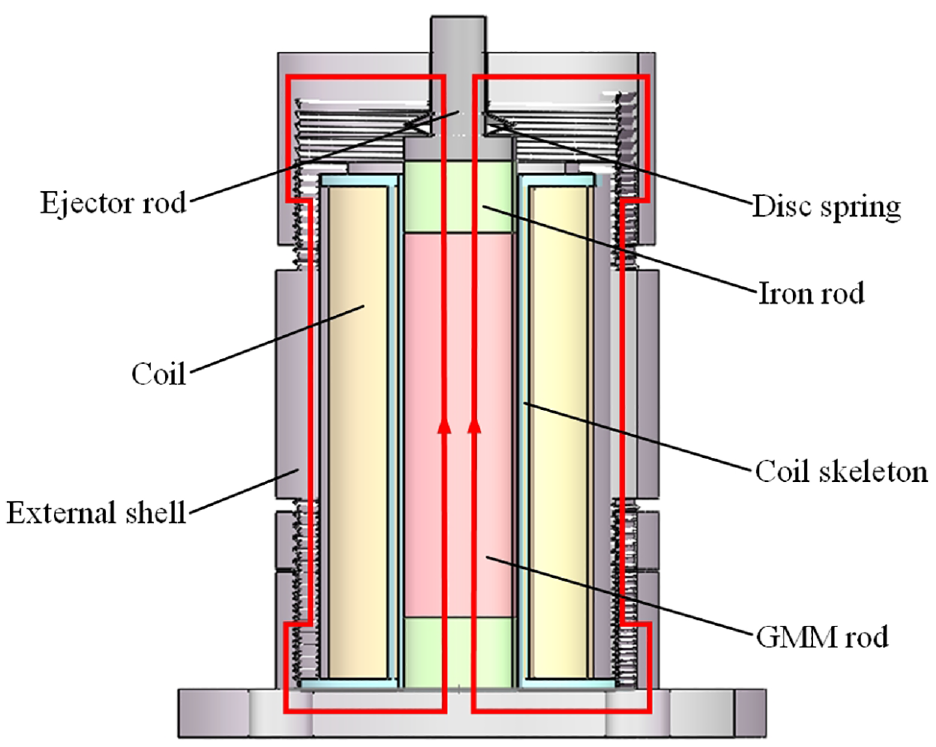
Internal structure and closed magnetic circuit of magnetostrictive transducer.
Modeling
The modeling and simulation are of great significance for the study of the energy conversion characteristics of the device and the establishment of the relationship between the external excitation and the output voltage. 29 In this section, the holistic theoretical model of transducer is established by using the magnetostrictive constitutive equations, and the concise analytical solution under different load conditions is derived.
According to the working process of GMM, the holistic theoretical model can be divided into three parts: mechanical model, electrical model, and magnetization model. To further simplify the model, the following assumptions will be followed in the modeling process.
When the external excitation acts on transducer, it is assumed that all the stress can be transferred to the GMM, and only the axial strain caused by stress is considered;
Assuming that the compressive stress and magnetostrictive strain generated by external excitation are uniformly distributed on the GMM rod, the whole transducer can be equivalent to a single-degree-of-freedom second-order linear steady system.
Mechanical model
As shown in Figure 2, magnetostrictive transducer can be equivalent to a second-order linear steady system with a single degree of freedom. Under the action of preload, the center position of the GMM rod in the equilibrium state is taken as the origin of coordinate, and the vertically downward direction along the X-axis is set as the positive direction.
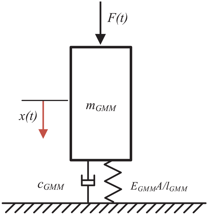
Equivalent dynamic model of magnetostrictive transducer.
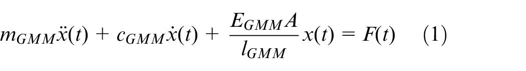
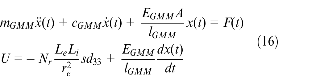
Where F(t) is the external excitation, and mGMM, cGMM, and EGMMA/lGMM are the equivalent mass, equivalent damping, and equivalent stiffness of the GMM rod respectively, x(t) is the relative displacement of GMM under external excitation, where mGMM is 1/3 of the actual mass, A and lGMM are the cross-sectional area and axial length of GMM respectively, and EGMM is the elastic modulus of GMM.
Under the action of external excitation, the solution of the differential equation can be divided into two parts: transient response and steady-state response. The transient response refers to the free vibration of the system. Due to the existence of damping, this kind of vibration only occurs in a period after the beginning of the vibration, and its amplitude will gradually decrease. The steady-state response is the forced vibration caused by external excitation. Since transducer usually works in an environment with periodic excitation, the forced vibration generated by external excitation can be approximately regarded as a kind of constant amplitude vibration. The theoretical model will focus on the output characteristics of transducer in the steady-state response phase.
When the external excitation acts on the magnetostrictive material, the total strain ε is
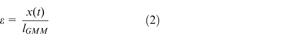
According to the characteristics of GMM, the total strain ε consists of the elastic deformation σ/EGMM caused by the stress σ and the magnetic strain d33H caused by the external magnetic field intensity H. Therefore, according to the magnetostrictive constitutive equations, the total strain ε of the GMM rod can be obtained as by the following equation.
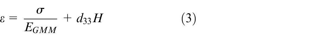
Where d33 is the magnetostrictive coefficient.
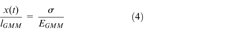
The holistic theoretical model established in this paper mainly describes the output voltage of the transducer, and the external magnetic field intensity H produced by the induced current in the coil can be neglected. 30 Therefore, the relationship between the vibration displacement x(t) and the stress σ can be obtained by further simplifying equations (2) and (3)
Electrical model
The structure and dimensions of the energy converting coil module in transducer are shown in Figure 3. Where Lcoil is the length of the coil skeleton, Le and Li are respectively the equivalent length and thickness of the coil. Consistent with the coil dimension, R1 and R2 represent the inner radius and outer radius, respectively. Then the equivalent thickness of the coil Li can be derived as

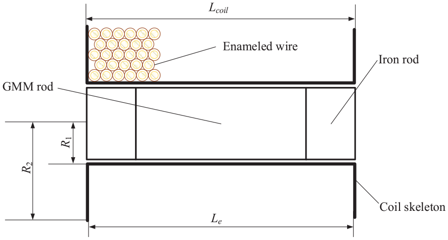
Dimension of the energy converting coil.
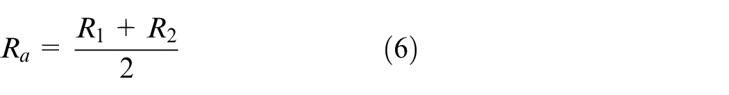
It can be inferred that the equivalent diameter Ra can be represented by
The output voltage of the coil could be obtained based on the dimension of the enameled wire. As shown in Figure 4, r
e
and ri are the outer diameter of the enameled wire and the copper wire inside the enameled wire, respectively, and the vertical distance between the centers of adjacent enameled wires is
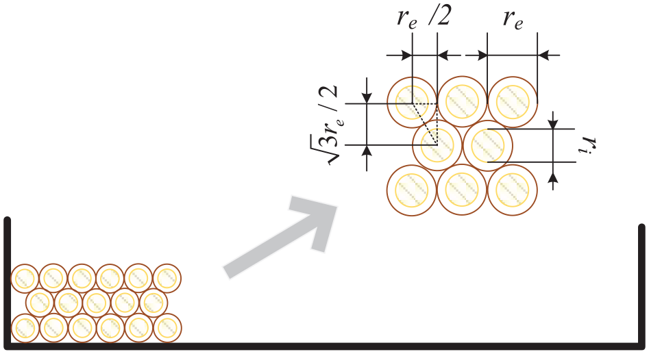
Relationship between the energy converting coil dimensions and the enameled wire dimensions.
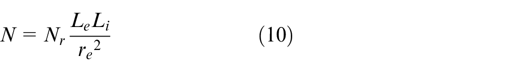
When the dimension of the coil skeleton are fixed, the number of coil turns largely depends on the diameter of the enameled wire, and the maximum number of coil turns in the horizontal and vertical directions is shown as follows:
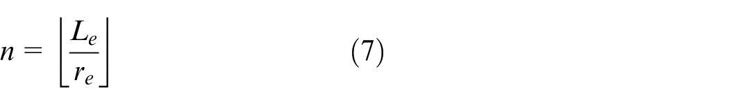
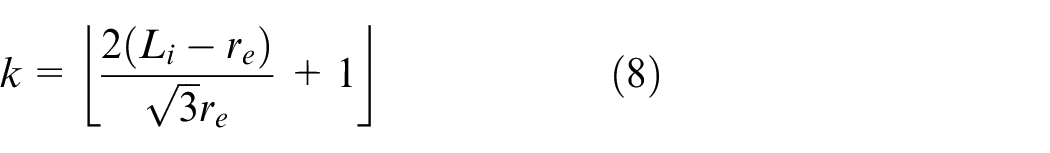
where ⌊⌋ represents rounding down to the nearest integer.
During the winding process, as is presented in Figure 5, there will be a coil gap between the coil and the coil skeleton, which could not be avoided. According to equations (7) and (8), the total number of turns of the coil can be derived as
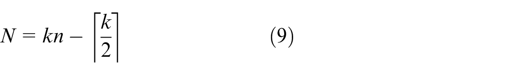
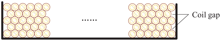
Coil gap of the coil.
Where ⌈⌉ represents rounding up to the nearest integer.
When considering the error caused by winding the coil, the model introduces a modification factor Nr, and get the expression of the modified coil turns can be simplified as
Nr is empirically determined from fabricating the coils.
Magnetization model
The magnetic induction intensity in magnetostrictive material is contributed by the stress induction and the magnetic field intensity. Under constant temperature, the magnetic induction B can be obtained from the magnetostrictive constitutive equations. 31

The permeability μ could be expressed as

μr and μ0 are the relative permeability and vacuum permeability of GMM respectively.
When the influence of the applied magnetic field H on the magnetic induction B is neglected, the magnetic induction B can be simplified as

Following Faraday’s law of electromagnetic induction, the induced voltage U is
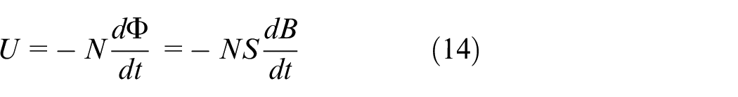
Where S is the equivalent radial cross-sectional area of the energy converting coil.
Substituting equations (4) and (11) into equation (14) gives
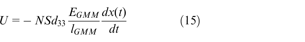
It can be seen from equation (15) that the output voltage of the transducer is proportional to the changing rate of the GMM deformation. Based on the above equations, the relationship between the external excitation F(t) and the output voltage U is finally established by rearranging equations (1) and (15).
Analytical solution
Since transducer usually works in an environment with periodic excitation, the periodic signal could be transformed into the superposition of multiple periodic harmonic signals through Fourier transform. Therefore, harmonic excitation is selected as the external excitation in this paper, and its corresponding expression is as follows:

Where F1 and ω are the amplitude and frequency of harmonic excitation respectively.
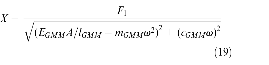
Then the response of GMM under the harmonic excitation is derived as follows:

The amplitude X and phase of displacement response φ are
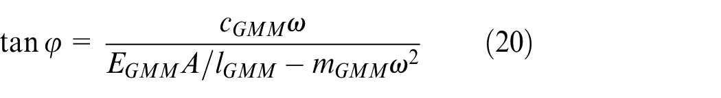
substituting equations (18) into (16) indicates that when the external excitation is harmonic, the output voltage and the phase can be derived below as
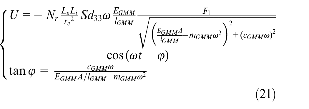
It can be seen from the analytical solution equation (21) that, under the action of harmonic excitation, the output voltage is linearly related to the amplitude of external excitation; when the material characteristic parameters of GMM are fixed, the phase of the output voltage will change with the change of external excitation frequency.
From equation (21), the voltage sensitivity is defined as
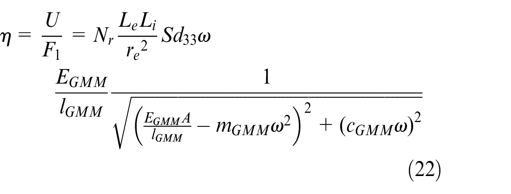
According to the above formula, the normalized voltage generated by a unit excitation could be quantified. It can be seen from equation (22) that voltage sensitivity varies with the frequency of external excitation and the internal dimensional parameters of the transducer. When exploring the influence of relevant parameters, firstly, the general trend of transducer voltage sensitivity change under different frequencies should be analyzed. On this basis, the internal dimensional parameters of the transducer are analyzed, and the influence of different dimensional parameters on the voltage sensitivity in different frequency range is discussed.
Experimentation
In this section, an experimental prototype is designed and fabricated, and a test rig is built based on the input and output characteristics of magnetostrictive transducer. On this basis, the dynamic response of the designed transducer under different mechanical loads is measured by the test rig, which is helpful to further explore the GMM characteristics and verify the accuracy of the holistic theoretical model describing the output performance. Since typical external excitations are usually distributed in the low-frequency range, this section will focus on measuring the output performance of the transducer under low-frequency excitation (f < 250 Hz). 32
The cross-sectional view of the designed transducer is shown in Figure 6. Transducer can be divided into four modules: external shell, preload adjustment structure, energy converting coil module, and energy conversion module. The shell of the transducer consists of a top cover, a middle cylinder, and a base, with threaded connections between the parts and fastened by a retaining ring. The top cover, disc spring, and ejector rod together constitute the preload adjustment structure, and the best output amplitude can be achieved by adjusting the top cover thread. The external excitation is transmitted through the ejector rod to the energy conversion module composed of a GMM rod and an iron rod. A piezoelectric sensor measures the mechanical load in real-time. The energy converting coil is composed of a 3D printed PLA coil skeleton and enameled wire coil. Relevant dimensional parameters for transducer are provided in Table 1.
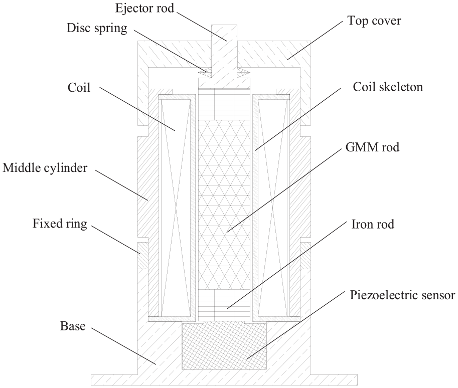
Sectional view of magnetostrictive transducer.
Properties and dimensions of the fabricated magnetostrictive transducer.
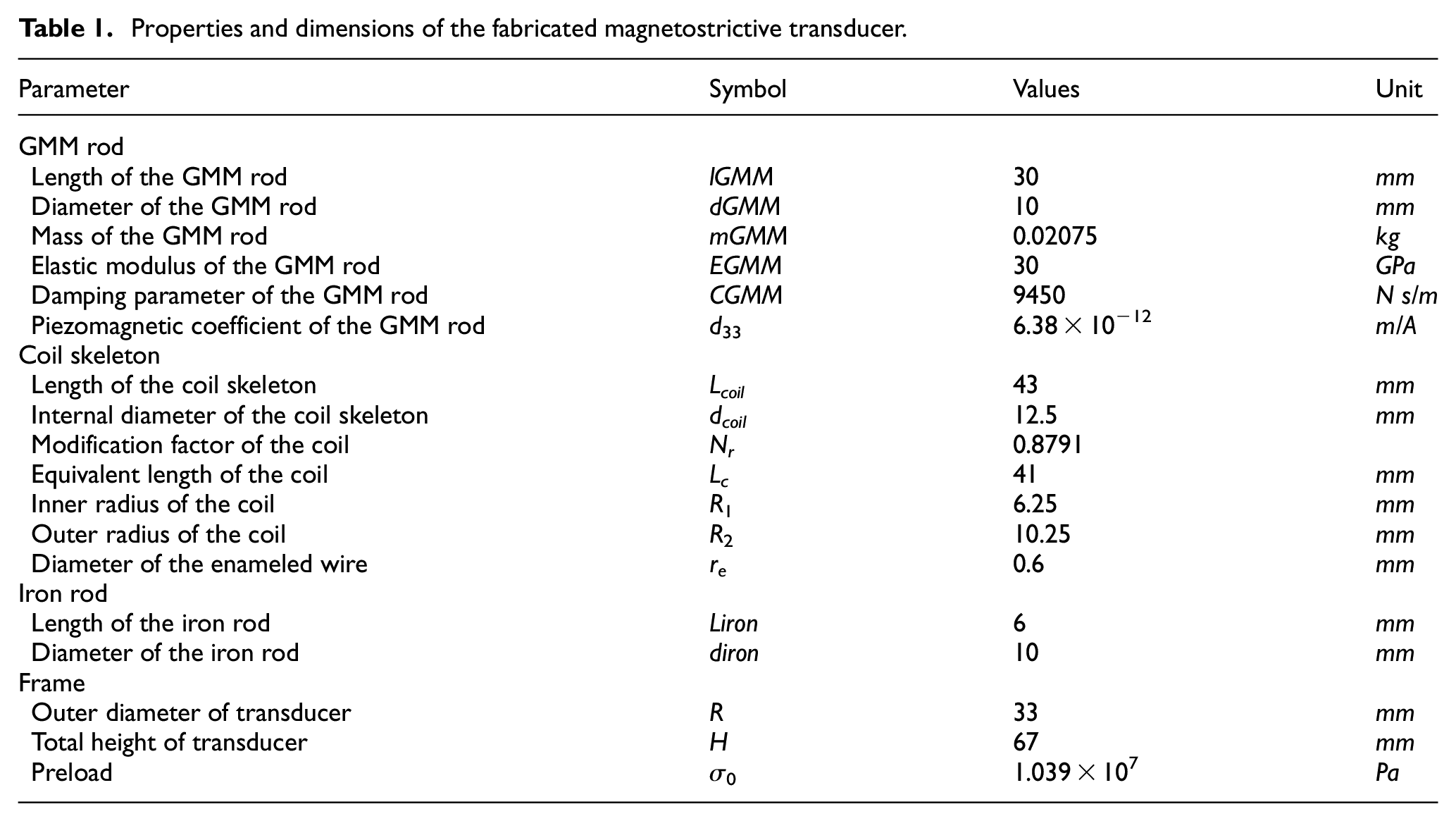
Figure 7 shows the test rig constructed to measure the transducer output performance. Rigol-DM3068 digital multimeter will be used to measure coil conductivity, resistance, and other parameters for the experiment. Rigol-DG1022U signal generator will be used to generate harmonic excitation signal, and YX5872 power amplifier will amplify the signal and drive the vibration shaker to work. The exciter, as the source of external excitation, will directly exert on magnetostrictive transducer(MT). Meanwhile, the coil will induce the change of magnetic induction intensity, and generate the induced voltage. At the same time, SA-1600 data acquisition system will collect the output voltage signal of the coil and piezoelectric sensor, and the experimental data will be measured and stored in real-time by the experimental test software.
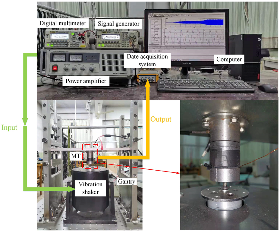
Experimental setup for testing the dynamic response of the proposed transducer.
Validation
In this section, the theoretical model simulation results of Section 3 are compared with the experimental results of Section 4. By analyzing the voltage sensitivity and phase characteristics under different mechanical loads, the accuracy of the holistic theoretical model in predicting output performance is verified.
Numerical verification
Figure 8 exhibits the voltage sensitivity characteristic curve of transducer with the mechanical load of fixed amplitude and different frequencies. It can be seen from the curve that the increase of frequency will significantly improve the voltage sensitivity of the transducer in the low-frequency range. The voltage sensitivity data collected from the experiment are evenly distributed along the simulation curve, and the overall trend has quasi-linear characteristics, with an average deviation of 3.18%. The actual output voltage of the transducer basically consistent with the theoretical calculation and simulation results.
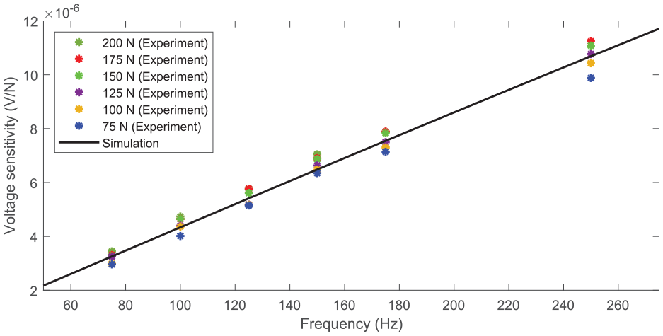
Voltage sensitivity versus frequency of external excitation.
The response curves of transducer phase characteristics at different exciting frequencies are revealed in Figure 9. The phase data collected from the experiment decrease with the enhancement of the exciting frequency, which is consistent with the simulation results, and the average deviation is 3.57%. It is further proved that the established model can accurately predict the output characteristics of the transducer. The curve shows clearly that the phase increases with the increase of exciting frequency, but does not change with the increase of exciting amplitude. It is proved from the side that the phase is independent of exciting amplitude.
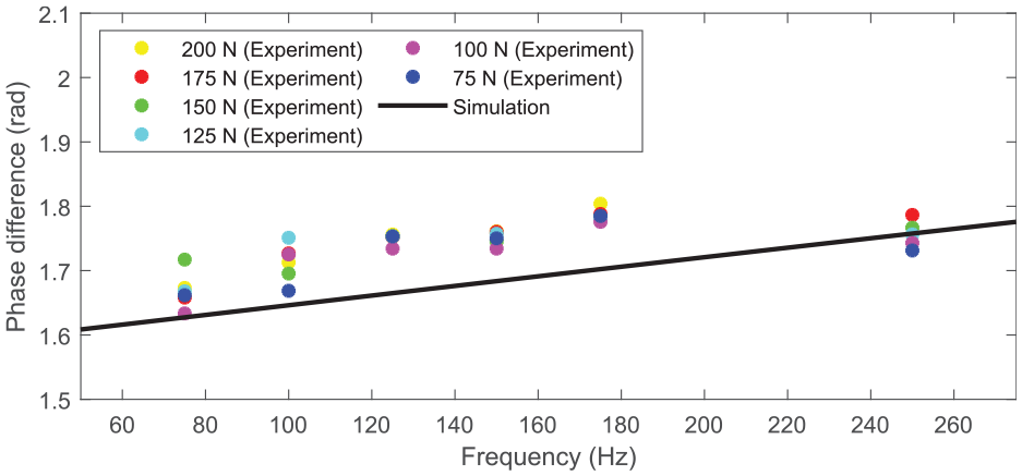
Phase versus frequency of external excitation.
Waveform verification
Figure 10 shows the experiment results and simulation results of transducer driven by harmonic excitation of 200 N amplitude and different frequencies. It can be observed that when external excitation is simple harmonic excitation, the response curve is also a quasi-simple harmonic curve, which keeps the same frequency as the external excitation. Under the condition of fixed exciting amplitude, the output amplitude increases with the increasing external excitation frequency. The output curve of the transducer is consistent with the modeling conclusion and simulation results, which verifies the accuracy of the holistic theoretical model in predicting the output performance.
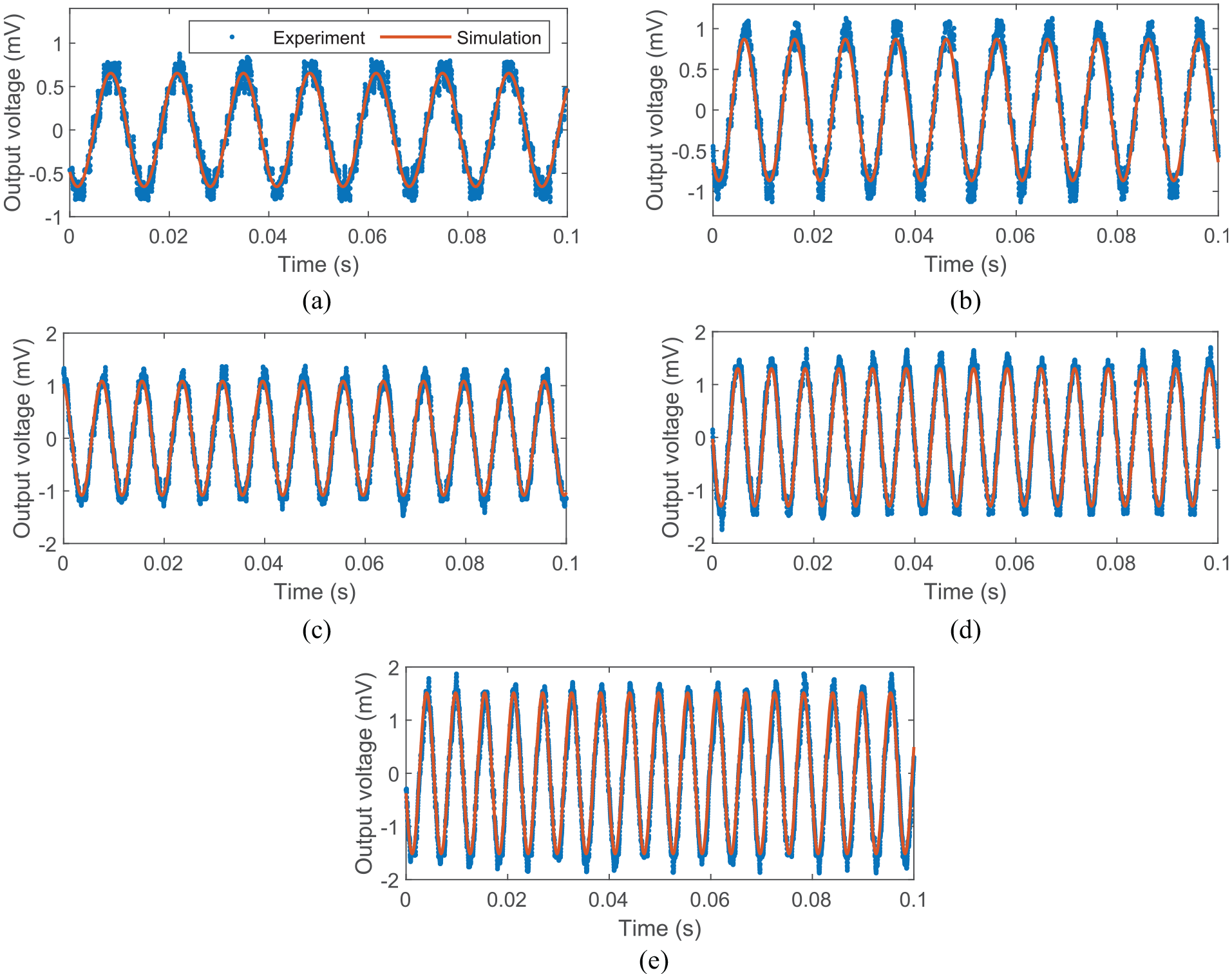
Open-circuit voltage obtained from simulation and experiment: (a) 200 N and 75 Hz, (b) 200 N and 100 Hz, (c) 200 N and 125 Hz, (d) 200 N and 150 Hz, and (e) 200 N and 175 Hz.
In order to verify the accuracy of the established model in predicting the output phase of the transducer, the maximum relative error of the phase (125 N, 100 Hz) is selected for analysis. As exposed in Figure 11(a), the output voltage curve obviously lags behind the curve of external excitation. Based on the established theoretical model, the phase between input and output curves mainly consists of the following two parts: Firstly, the first part of the phase is the inherent phase φ1 between the external excitation and the steady-state response displacement; Secondly, It can be seen from the equation (15) that the output amplitude of the transducer is inverse to the displacement change rate under the steady-state response of GMM, as shown in Figure 11(b), resulting in another part of the phase φ2 = π/2.
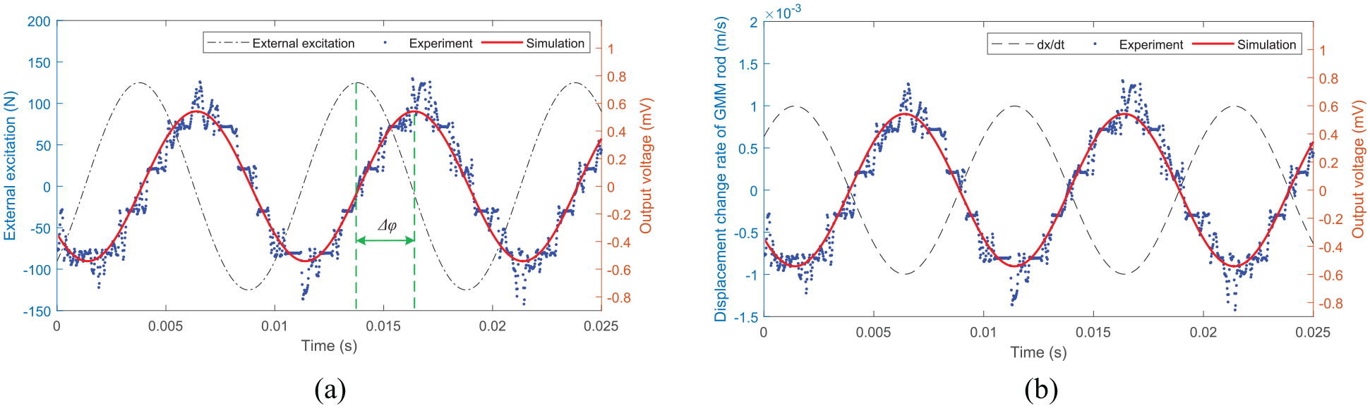
Phase between external excitation and output voltage: (a) Phase of external excitation and output voltage (125 N, 100 Hz), and (b) Phase of GMM rod displacement response rate and output voltage (125 N, 100 Hz).
Parametrical optimization
This paper proposed voltage sensitivity in transducer optimization. Voltage sensitivity is an important indicator to measure the energy conversion efficiency of the transducer. By analyzing transducer internal dimension parameters under different mechanical loads, the influence of mechanical load on voltage sensitivity is discussed. On this basis, the method to further improve voltage sensitivity is provided by optimizing relevant structural parameters.
Based on the theoretical analysis and experimental verification, this section will use the above theoretical models to discuss the influence of exciting frequency and internal structural dimensions on voltage sensitivity. The conclusion of parameter analysis will guide the optimized design of magnetostrictive transducer with higher performance.
Critical frequency for a quasi-linear range of the voltage sensitivity
The change of external excitation frequency will rapidly vary the voltage sensitivity of the transducer. Therefore, the analysis of voltage sensitivity trend under different exciting frequencies will provide a basic reference for the analysis of other parameters. Under different exciting frequencies, the voltage sensitivity is exposed as Figure 12. In the lower frequency range, the voltage sensitivity of the transducer increases uniformly with the increase of the frequency, showing a good approximate linear relationship; with the continuous improvement of exciting frequencies, the voltage sensitivity of the transducer reaches stable, and then decrease gradually.
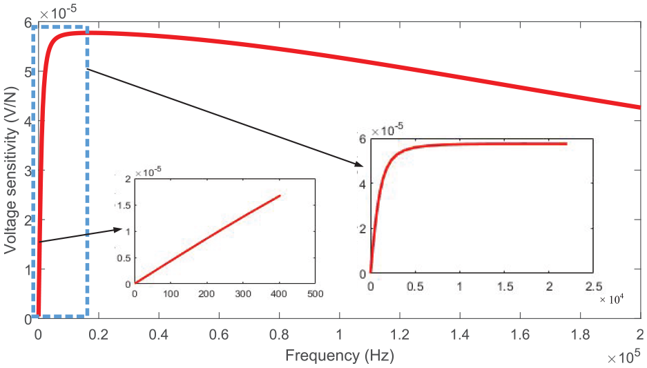
Voltage sensitivity under different exciting frequencies.
The reason for this phenomenon could be illustrated via equation (22), which reveals the relationship between the exciting frequency and transducer voltage sensitivity. When adjusting the frequencies in Eq. (22) to the denominator, we can see that, in the lower frequency range, the term
On the other hand, if designers are seeking a higher resolution for driving frequencies, they can intentionally tune the critical frequency toward the lower frequency range.
Effect of GMM rod dimensional parameters on transducer voltage sensitivity
As the core component of transducer energy conversion, the dimension change of GMM will have a serious impact on the output performance of transducer.33,34 The following figure details the effect of GMM rods of different lengths and diameters on voltage sensitivity.
In terms of length, Figure 13 shows that the peak voltage sensitivity decreases with the increasing length of GMM rod, and the difference between voltage sensitivity of adjacent lengths decreases, but the voltage sensitivity tends to be consistent with increasing frequency. The main reason for this phenomenon is that under the same stress conditions, shorter GMM rods will produce larger strains, which can be obtained from equation (4), and the change rate of strain will directly determine the output amplitude of the transducer, so shorter GMM rods will process higher voltage sensitivity.
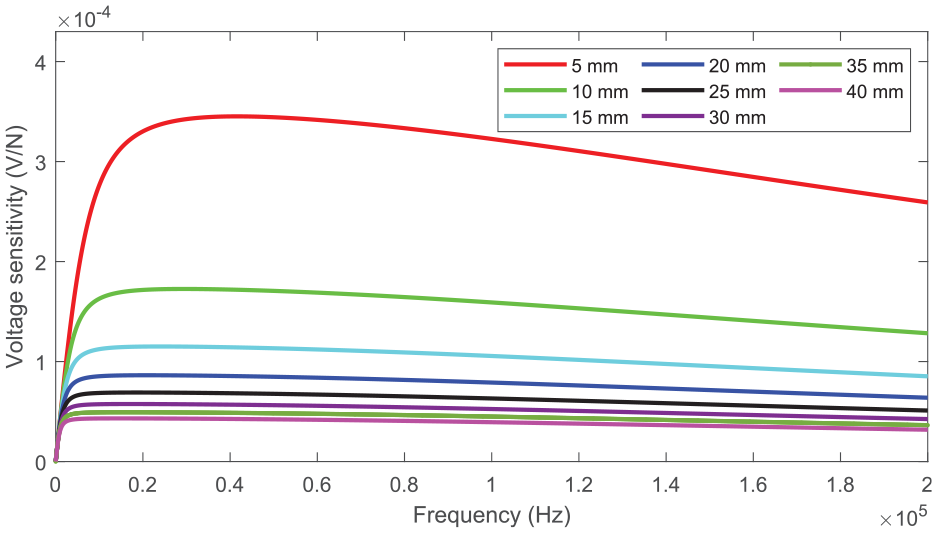
Voltage sensitivity versus length of GMM rod under different exciting frequencies.
As is presented in Figure 14, the transducer using GMM rod with a smaller diameter can achieve the peak value of voltage sensitivity at a lower frequency range. Combining equations (4) and (15), it is illustrated that the stress change rate is linearly related to the output amplitude of the transducer, and under the same exciting amplitude, the smaller cross-sectional area is more sensitive to the change of exciting stress, so the GMM rod with a smaller diameter will realize the maximum voltage sensitivity faster.
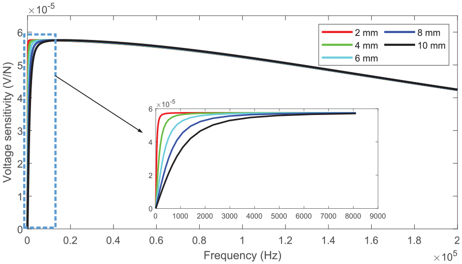
Voltage sensitivity versus diameter of GMM rod under different exciting frequencies.
Under the action harmonic excitation of 16.96 kHz, Figure 15 shows the voltage sensitivity of transducer with different GMM dimensions. It can be seen from the figure that the voltage sensitivity increases with the decrease of GMM rod dimension, but the influence of GMM rod length on the voltage sensitivity is more obvious, and the maximum voltage sensitivity is 8.6297 ×10⁻⁴ V/N. However, we can also note that under the same mechanical load, choosing a smaller GMM will help to obtain a higher voltage sensitivity in a lower frequency range, but the smaller GMM will not only affect the overall strength of the material but also increase the difficulty and cost of manufacturing. Therefore, we should determine the dimension of the GMM rod according to the actual exciting excitation characteristics of the transducer.
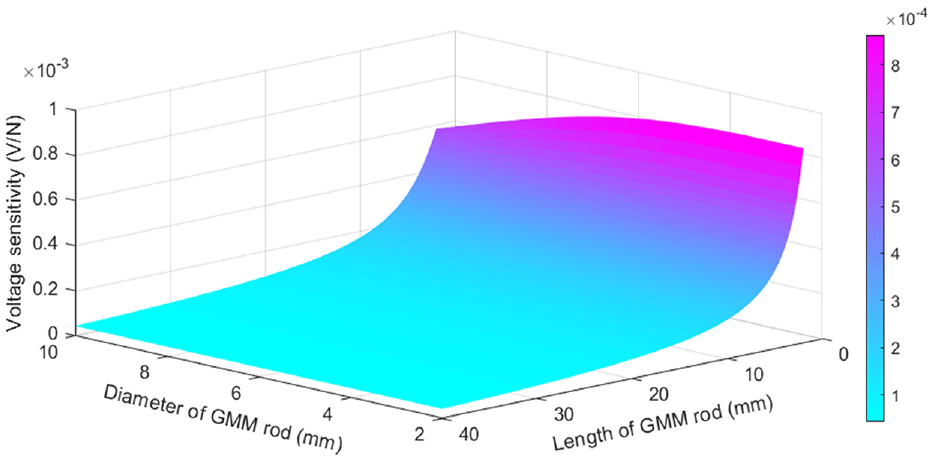
Voltage sensitivity with different GMM rods dimensions.
Effect of coil dimension on transducer voltage sensitivity
Under the action of external excitation, the coil will collect the change of magnetic induction intensity inside GMM, and finally complete the conversion of exciting mechanical energy to electrical energy.25,35 The following figure simulates the influence of coils with different dimensions on voltage sensitivity.
As shown in Figure 16, when the equivalent coil width is constant, the voltage sensitivity of the transducer increases uniformly with the increase of coil length. The main reason is that, as shown in equation (14), there is a linear relationship between the number of turns of the coil and the final output amplitude of the transducer, so that the voltage sensitivity of the transducer increases uniformly with the increase of the total coil length.
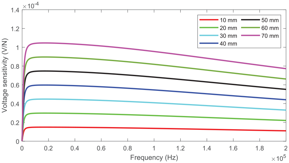
Voltage sensitivity versus length of the coil at different Frequence.
Figure 17 shows that increasing the coil width will significantly improve the voltage sensitivity of the transducer. When the equivalent length of the coil is fixed, the increase of the equivalent width of the coil will lead to the increase of the coil and average winding diameter, thus promoting the improvement of the transducer voltage sensitivity.
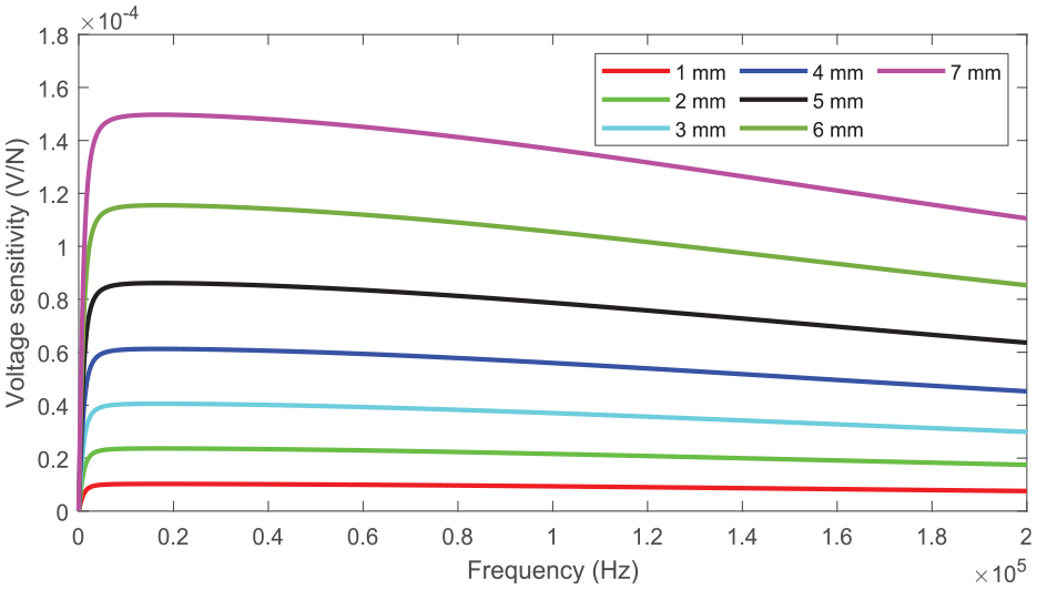
Voltage sensitivity versus width of the coil at different Frequence.
Figure 18 exhibits the voltage sensitivity of transducers with coils of different lengths and widths under the harmonic excitation of 16.96 kHz. In the figure, we can see that the coil dimension will significantly amplify the voltage sensitivity of the transducer within a specific range. Compared with changing the equivalent length, Increasing the equivalent width of the coil will lead to more significant enhancement. However, while increasing the equivalent width, the air gap between the outer coil and GMM rod will inevitably lead to leakage of magnetic flux in the magnetic circuit. Therefore, in practical application, the coil diameter should be avoided.
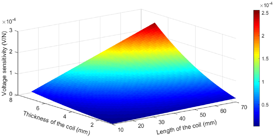
Voltage sensitivity with different coil dimensions.
Usually, the power performance of an energy harvester is evaluated with an optimal load resistor (i.e. the impedance between the harvester and the load resistance is perfectly matched). Nevertheless, the voltage amplitude across the load resistance, when the impedance is fully matched, may be much smaller than its open-circuit condition. Here, a conflict is an encounter that only a very small voltage sensitivity magnitude could be achieved when the maximum instant power is reached. Moreover, to calculate the optimal output power of magnetostrictive transducer calls for a more comprehensive and complicated impedance model of the coils and the GMM rod, which is beyond the scope of this paper. Thus, we decide not to include the power generation contents in this paper.
Conclusion
This paper provides a general dynamic modeling and analysis method for magnetostrictive transducer, and attempts to explore the influence of relevant parameters on voltage sensitivity. Theoretical analysis and experimental work lay an important foundation for the optimization and application of transducers in the next stage. The major conclusions are as follows.
A holistic theoretical model is established to quantify the voltage output performance, which provides theoretical support for quantitative analysis of transducer output performance;
This paper proposed the concept of voltage sensitivity in transducer optimization to quantify the normalized voltage generated by a unit excitation;
A prototype of transducer is fabricated, and harmonic experiments are conducted under different mechanical loads, which verifies the theoretical model and voltage sensitivity of magnetostrictive transducer;
According to theoretical simulation and experimental verification, the influence of internal dimensional parameters on voltage sensitivity with different excitation levels is investigated. The trend of voltage sensitivity is determined by the exciting frequency of external excitation and the internal dimensional parameter;
Based on the dimensional parameter analysis, compared to the diameter of GMM rod, the reduction of length exhibits a specific capacity of improving the voltage sensitivity under different mechanical loads, while the magnetostrictive material with smaller diameters will obtain the maximum voltage at lower frequencies. For the coil dimension, increasing the effective thickness can cachieve a greater voltage sensitivity improvement than the effective length.
Footnotes
Declaration of conflicting interests
The author(s) declared no potential conflicts of interest with respect to the research, authorship, and/or publication of this article.
Funding
The author(s) disclosed receipt of the following financial support for the research, authorship, and/or publication of this article: This work is supported by the National Science Foundation of China (Project No.51275525).