
Abstract
This paper presents control design based on an Interval Type-2 Fuzzy Logic (IT2FL) for the trajectory tracking of 3-RRR (3-Revolute-Revolute-Revolute) planar parallel robot. The design of Type-1 Fuzzy Logic Controller (T1FLC) is also considered for the purpose of comparison with the IT2FLC in terms of robustness and trajectory tracking characteristics. The scaling factors in the output and input of T1FL and IT2FL controllers play a vital role in improving the performance of the closed-loop system. However, using trial-and-error procedure for tuning these design parameters is exhaustive and hence an optimization technique is applied to achieve their optimal values and to reach an improved performance. In this study, Social Spider Optimization (SSO) algorithm is proposed as a useful tool to tune the parameters of proportional-derivative (PD) versions of both IT2FLC and T1FLC. Two scenarios, based on two square desired trajectories (with and without disturbance), have been tested to evaluate the tracking performance and robustness characteristics of proposed controllers. The effectiveness of controllers have been verified via numerical simulations based on MATLAB/SIMULINK programming software, which showed the superior of IT2FLC in terms of robustness and tracking errors.
Introduction
The parallel robots are mechanisms with two or more kinematic chains linked to their end-effectors. They are better known because of the good performance when it takes care of acceleration, precision, stiffness, and capacity to carry heavy loads. The parallel robots are adequate instruments for applications in different fields such as in machining, welding, handling, flight simulators, and telescopes pointing. They have also advantages related to their sensitivity, which make them very suitable for applications in medicine, like endoscopy and other procedures that should be minimum invasive.1–3
The parallel manipulators have many positive features. Their actuators are fixed to the base, which decreases the mass and allows high acceleration; due to the parallel action, these actuators provide high stiffness and efficient load capacity. Theoretically, when compared to serial manipulators, their accuracy is better. The good precision is a result of the fact that parallel manipulators have errors in the position given by average errors of individual chains. Their repeatability is also high, which is due to kinematic chains that are closed. However, the parallel manipulators have some drawbacks: the workspace is limited and the behavior of singularities is more complicated than in serial manipulators.1–6
Parallel mechanisms can be used in humanoid robots in order to improve their structure and operation performance as inspired by human anatomy. In recent years significant advances have been made in Human-Robot Interaction (HRI). 7 Hand gestures have been investigated as the most natural tools of interaction for human beings, and particularly for disabled persons. 8 Some parallel mechanisms are utilized to mimicking human neck, 9 others are used to improve the imitation skill and children with autism. 10 Other parallel mechanisms are utilized for manufacturing anthropomorphic exoskeletons which matching and mimicking the real motions of some body parts, such as lower and upper limb exoskeletons, to be worn by elderly and disable persons. 11
The redundant manipulators offer a safe physical collaborative flexible workspace for nurse or surgeon (assisting physicians, patient support) undergoing surgery. During the past decades, the development of surgical robot systems and teleoperated surgery, which mostly involve articulated (serial and parallel) robot configurations, has witnessed rapid growth due to the advancements in computing and sensor technologies.12,13 In the tele-operated surgery, the surgical robots have to show both safe and flexible manipulation. On the contrary of serial robot manipulator, which are featured by flexible motion, the parallel robots suffers from limitation in workspace. However, the surgical parallel robots are characterized by higher accuracy and less vibration than serial counterparts. This makes them candidates for such medical applications that require high precision and safe operation.14,15
In this study, a planar parallel robot of the kind 3-Revolute–Revolute–Revolute (3-RRR) with 2-Degrees-Of-Freedom (DOF) will be considered. Many researchers have conducted their control design for tracking control of 2-DOF planar redundant parallel robot. Zhang et al. proposed an augmented PD controller with forward dynamic compensation for a redundant planar 2-DOF parallel manipulator. Better Accuracy has been achieved with the compensation of active joint friction and the proposed controller is easy to implement and it requires shorter sampling period and it shows better performance than simple PD controller. 16 Chen et al. proposed a simple scheme for computing the inverse dynamics of 2-DOF planar redundant parallel manipulator. The study developed four control algorithms, represented by two PD controls, an augmented PD control, and a computed-torque control scheme for control purpose. The experimental results showed that the model-based controllers have better than PD controllers. 17 Yu et al. have presented a novel Udwadia–Kalaba approach or 2-degrees of freedom redundant parallel manipulator. This approach can represent the direct and inverse dynamical models of the robot precisely and explicitly. 18 Sariyildiz et al. 19 applied a new Artificial Intelligent-based inverse kinematic solution method for the planar redundant robot manipulator using support vector machine method (SVM). Al-Mayyahi proposed fractional order proportional integral derivative (FOPID) controller for the path tracking control of the center of the 3-RRR planar parallel robot. The design parameters FOPID controller is optimized using the bat optimization algorithm for better improvement of controller’s performance. 20 Liu focused on the solution of the singularity problem in Redundant Parallel Manipulator. Three kinds of redundant methods are developed and discussed. The kinematic and dynamic control methods are applied for trajectory tracking of redundantly actuated parallel mechanisms. 21 Shang and Cong applied a new robust nonlinear controller to a planar 2-DOF parallel manipulator. The controller combines nonlinear PD control with the robust dynamic compensation. The NPD control is used to compensate disturbances, unmodeled dynamics, and friction, while the robust control part is used to compensate the model uncertainties of the robot. The proposed controller showed better trajectory tracking accuracy as compared to augmented PD controller. 22 Sheng and Li have proposed optimized PID control design for trajectory tracking control of 3-RRR parallel robot. The Genetic Algorithm (GA) is applied for tuning the design parameters of PID controller in order to improve the robustness of controller and precision of trajectory tracking. 23 Moezi et al. presented robust optimal fuzzy logic controller for trajectory tracking of 3-RRR parallel robot based on PWM technique. The modified Cuckoo Optimization Technique has been applied for tuning the parameters of FL controller. The proposed control scheme showed better robustness characteristics and tracking performance when compared to optimal PID controller. 24 Noshadi et al. presented active force control (AFC) for 3-RRR planar parallel manipulator. The AFC has showed better robustness characteristics and better disturbance rejection capability as compared to conventional PID controller. 25
Taking advantage of the fact that, compared with conventional controllers, the Fuzzy Logic Controllers (FLC) can be considered to be more robust and less sensitive to variations in parameters. 26 There are many researchers who have used and proved the efficacy of FLC in various applications like cruise control systems, cyber defense mechanism, and parallel robots.27–29
In the past few years, fuzzy control has been a topic of great interest in the area of robot control. In Moezi et al., 24 the Cuckoo Optimization Technique has been used for tuning the design parameters of FLC to improve its tracking performance and robustness against variation of parameters. A fuzzy-based controller was proposed by Stanet et al. for an application in medicine with a 3-DOF parallel robot. 28 The fuzzy controller provided more accurate results than a classical proportional-integral-derivative controller. In Noshadi et al., 30 Noshadi et al. designed two level fuzzy tuning resolved acceleration control (FLRAC) for trajectory tracking of 3-RRR planar parallel robot. The first level of FLC is used for acquiring the gains of PD controller. The second level is used for tuning the parameters of fuzzy controller to improve the performance. The FLRAC is combined with AFC to enhance the robustness and accuracy. Lu et al. have proposed an optimization procedure to design and tune Interval Type-2 Fuzzy Logic Controller (IT2FLC) and PID IT2FLC for the tracking control of Delta parallel robot.31,32 The aim was to improve the robot control accuracy; however, it was also considered that a good control program must-have characteristic such as simplicity, applicability, robustness, and stability.
The theory of fuzzy sets, proposed by Lotfi Zadeh in 1965, originated the Type-1 FLC (T1FLC), which was extended by Zadeh in 1975, originating the Type-2 FLC (T2FLC).33,34 In T1FLC, the uncertainties related to the membership functions can be described in just two dimensions, whilst T2FLC can properly deal with them in three dimensions, which make it able to handle numerical uncertainties and also nonlinearities. So, T2FLC can replace T1FLC in problems with complex nonlinear systems.35–37
To improve the dynamic response of the closed-loop system, FLCs must have PI-type or PD-type control structures. Here in this work, a PD-like FLC structure is considered. Although, as in the classical PID controllers, the selection of the PD gain parameters using a trial and error procedure does not give an optimal solution. So, optimization techniques can be applied to tune these parameters.38–41
In the present work, the Social Spider Optimization (SSO) algorithm is applied to tune the scaling factors in the output and input of an Interval Type-2 PD-Like Fuzzy Logic Controller (IT2PDFLC) for the position control of parallel manipulator. So, the goal is to obtain optimal values toward the minimum value of the cost function and hence to improve the closed-loop system dynamics. It is also presented in this paper the design of a Type-1 PD-Like Fuzzy Logic Controller (T2PDFLC) for the position control of the 3-RRR parallel robot, was the SSO algorithm is also used to tune the design parameters. Therefore, the scope of this work can be summarized by:
□ Design of IT2PDFLC for a 2-DOF planar 3-RRR parallel robot.
□ Dynamic performance improvement of T1PDFLC and IT2PDFLC using SSO.
□ Comparative analysis between T1PDFLC and IT2PDFLC controllers in terms of dynamic performance and robustness.
The model of planar 3-RRR parallel robot
In this section, the mathematical model of the planar 3-RRR parallel manipulator will be analyzed. For this kind of parallel robot, the solution is not unique for neither Direct Kinematics nor to Inverse Dynamics. So, there are discussed just Inverse Kinematic Model (IKM), Forward Kinematic Model (FKM), and Direct Dynamic Model (DDM).
Forward kinematic of (planar 3-RRR) parallel robot
The setup of 3-RRR parallel robot consists of three actuators (redundantly actuated) with tip point connected to three identical branches, being each branch planar with 2-DOF (translation along x-y) as shown in Figure 1. In such a system, the acceleration of the end-effector ranges between (7.2–15)
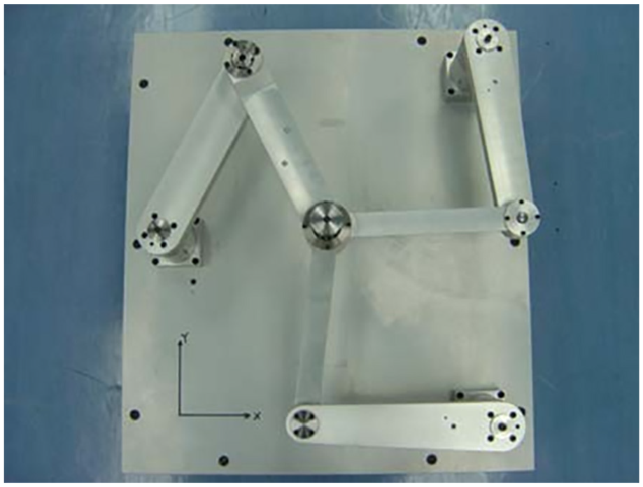
Mechanisms of the 3-RRR.
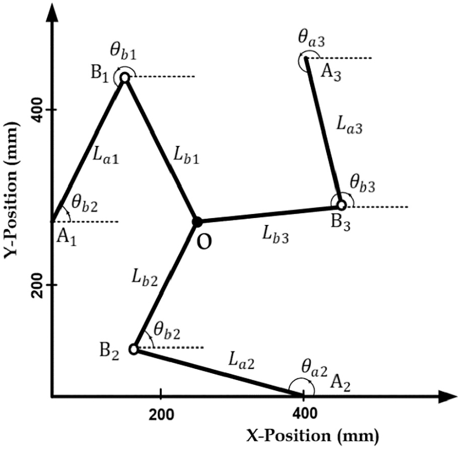
Scheme of a planar 3-RRR parallel robot.
The problem of forward kinematic is related to the computation of the position in the Cartesian frame of the end point
where
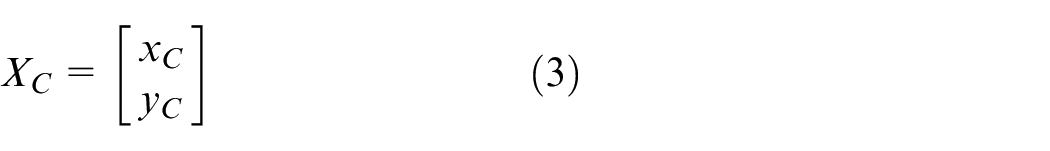
The point C describes the position of the end-effector, which is determined by:
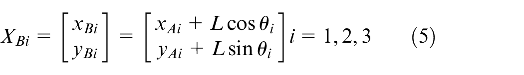
From Figure 2, one can have

Equation (2) can be written as
Taking equations (3) and (5) and finding a solution for
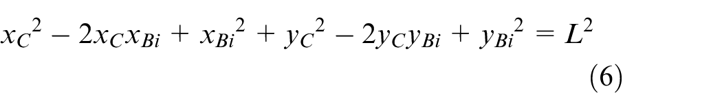
Using equation (5), the norm of

The substitution of equation (7) into equation (6) provides the equations of links (1), (2), and (3);


Taking equation (8) and subtracting equations (9) and (10), respectively, gives:

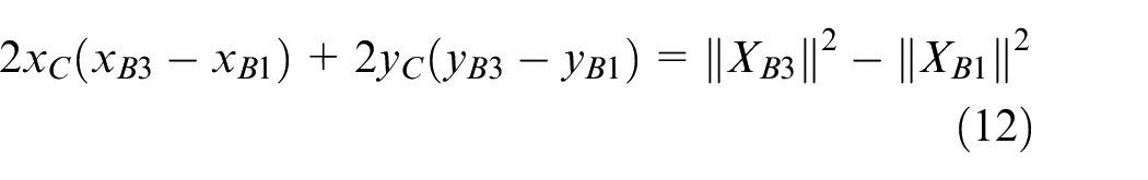
Using a matrix notation, equations (11) and (12) can be written together as:
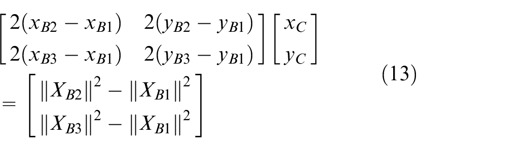
It can be easy shown that
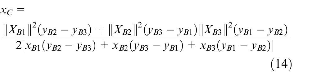
Using equation (13) and follow the same analysis as above, one can find the
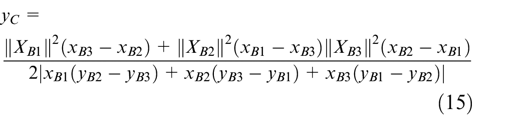
It is worthy to note that without the third leg, it is possible to find solutions to any two-leg planar manipulator considering the forward kinematic. These constraints lead to a unique solution of the forward kinematic problem.
Inverse kinematic
The problem of the inverse kinematic can be characterized by the computation of the actuator joint angles

where,
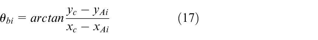
Hence
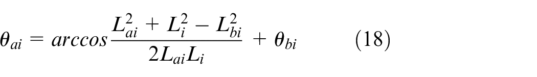
There are two solutions related to equation (18), which result from the “arc cos” function. As there are two solutions for each leg, it means that the manipulator has eight solutions. It is also important to notice that the actuated joints are placed on the vertices of a triangle.
Direct dynamic model
In this work, the Euler-Lagrange equation is considered for the development of the dynamic model of the 3-RRR parallel manipulator. The general motion of the 3-RRR manipulator may be represented by the serial kinematics chains subjected to constraints in the closed loop. Also, the parallel manipulator dynamics can be given by the combination of the dynamics of the serial kinematic chains with their related force constraints.
Dynamic model of serial kinematic chain
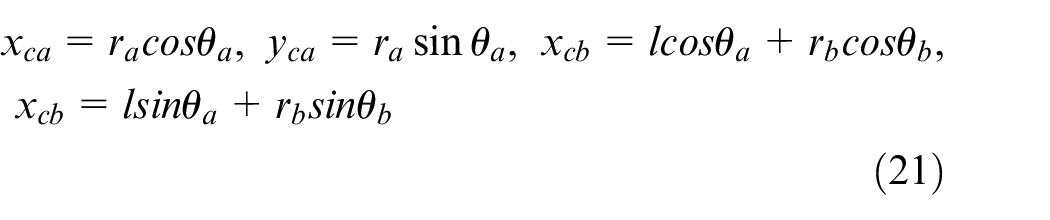
The 3-RRR parallel robot can be divided in three serial kinematic chains based on its cutting at the end-effector O, being each chain a planar 2-DOF serial robot with two links and two joints. A scheme for the serial kinematic chain is presented as shown in Figure 3.
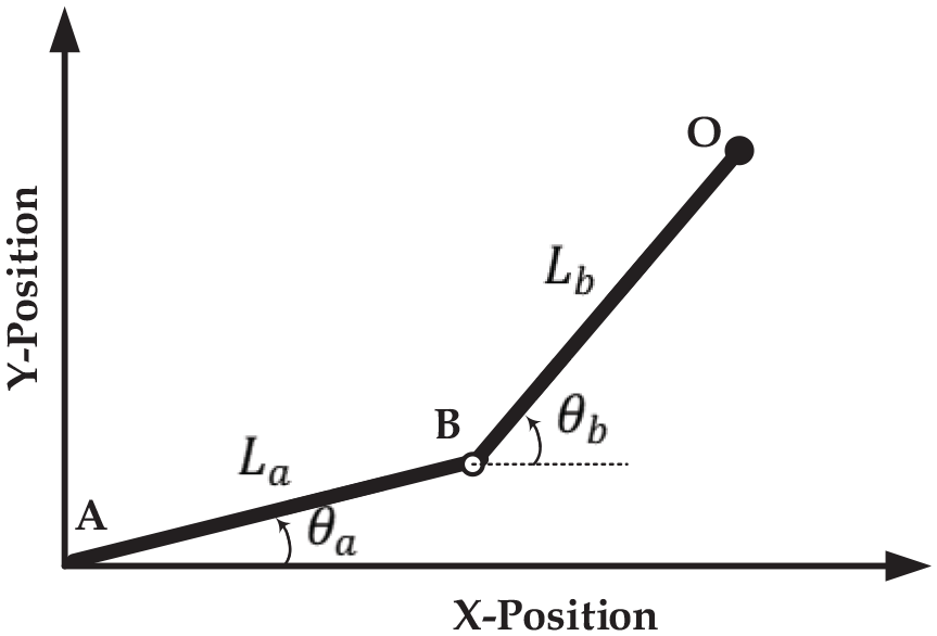
Scheme for the serial kinematic chain.
As the motion of the kinematic chain is performed in the horizontal plane, it is possible to ignore the gravity effect. Thus, the links have kinetic energy
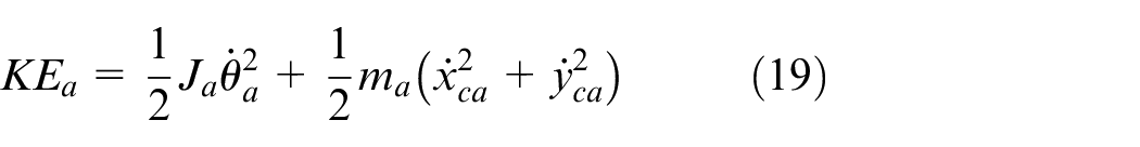
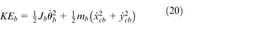
where
Taking the derivative of equation (21) and substituting into equations (19) and (20) give
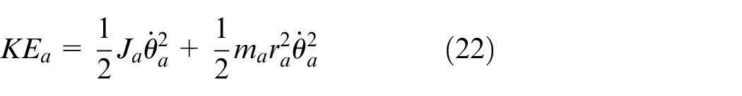
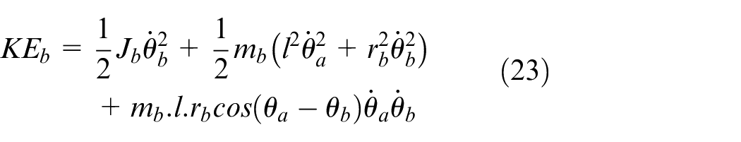
The kinematic chain kinetic energy is derived from equations (22) and (23):
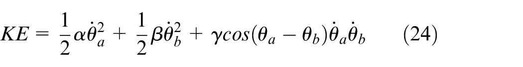
where the symbols

Let
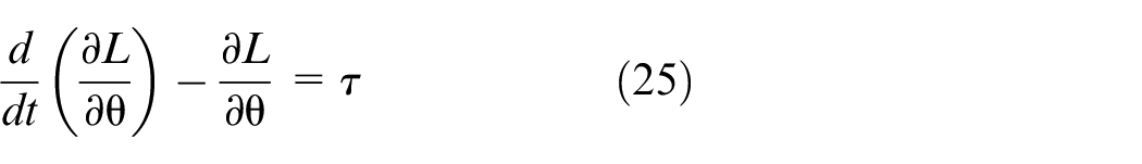
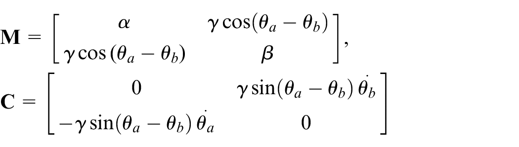
Expanding equation (25), the kinematic chain has a dynamic that can be expressed by:

where the matrices
Dynamic model of parallel manipulator
The 3-RRR parallel manipulator has a dynamic model derived from the serial manipulator dynamic model. As such, the parameters of the serial kinematic chains are
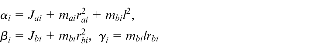
where

where
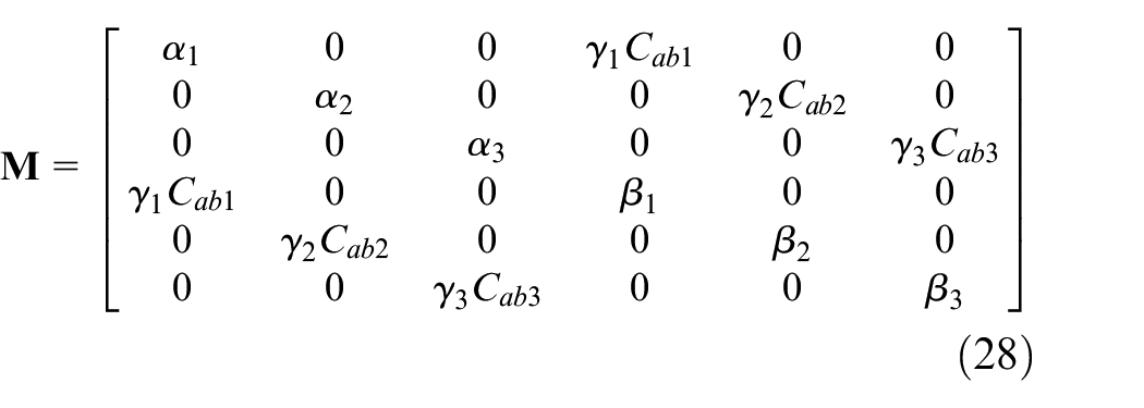
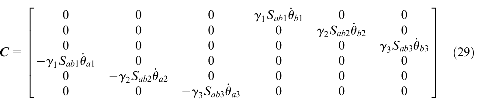
In equations (28) and (29), the symbol
Type-2 Fuzzy Logic Control
Type-2 fuzzy logic theory
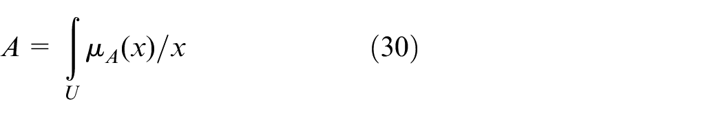
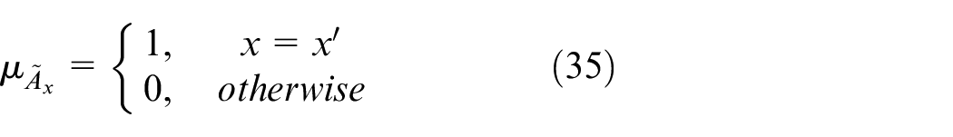
The membership function in the fuzzy sets represents the degree of membership of an element. The Type-1 Fuzzy Set (T1 FS) named A comprises the domain of real numbers U (which is the universe of discourse) and also the membership function (MF) (
A type-2 fuzzy set (T2 FS)

where
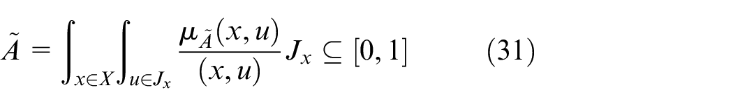
where ∫∫ represents the union overall admissible
Figure 4 shows the membership function (MF) of Type-2 Fuzzy Logic set. A vertical slice of the T2 MF at
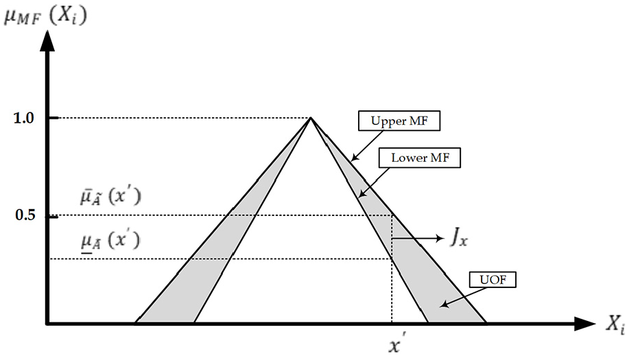
The structure of membership function for Type-2 FLC.
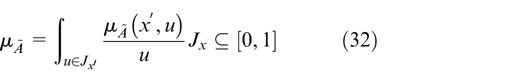
The secondary membership function associated with
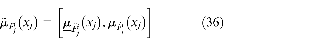
The lower and upper MF of
Structure of IT2FL control
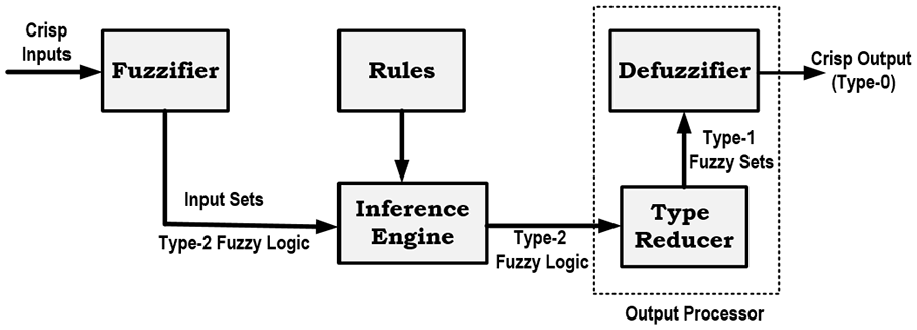
The IT2FLC has a structure that is almost the same of the T1FLC, but the membership functions are different. This structure can be seen in Figure 5. The fundamental form of the IT2FLC are Fuzzifier, Rule base, Inference engine, Type-reduction, and Defuzzification.26,37
Structure of T2FLC.
Fuzzifier
Inputs are mapped, by the fuzzifier, into Type 2 Fuzzy Sets (T2 FS), starting the inference engine. The implementation of the fuzzifier for the T2 FS can be performed in a simple manner by the mapping of a crisp input in a Singleton FS, as represented by37,42
Rule base
In Type-2 FLSs the Rule-Base is also synthesized in a set of If-Then rules, which establish the relationship between the input and output of the system. The Type-2 FLS rule can be represented as follows 37 :
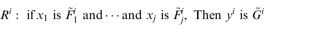
where
Inference engine
Fuzzy inputs are assigned to fuzzy outputs by the Inference Engine (IE), which is performed using the operators and base rules, including union and intersection operators. The IE is the essential difference between T2 and T1 FLS. In IT2FS, the resultant operation is described as an interval depicted by
where
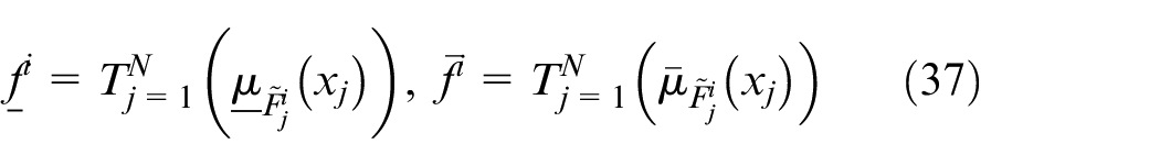
being
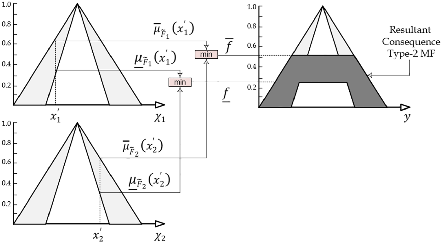
Mamdani inference minimum operation used by Type-2 FSs.
In this work, IT2FLS applies the Mamdani minimum implication method, as the t-norm operator, to the rule’s firing level
Switching points in computing
Type reduction
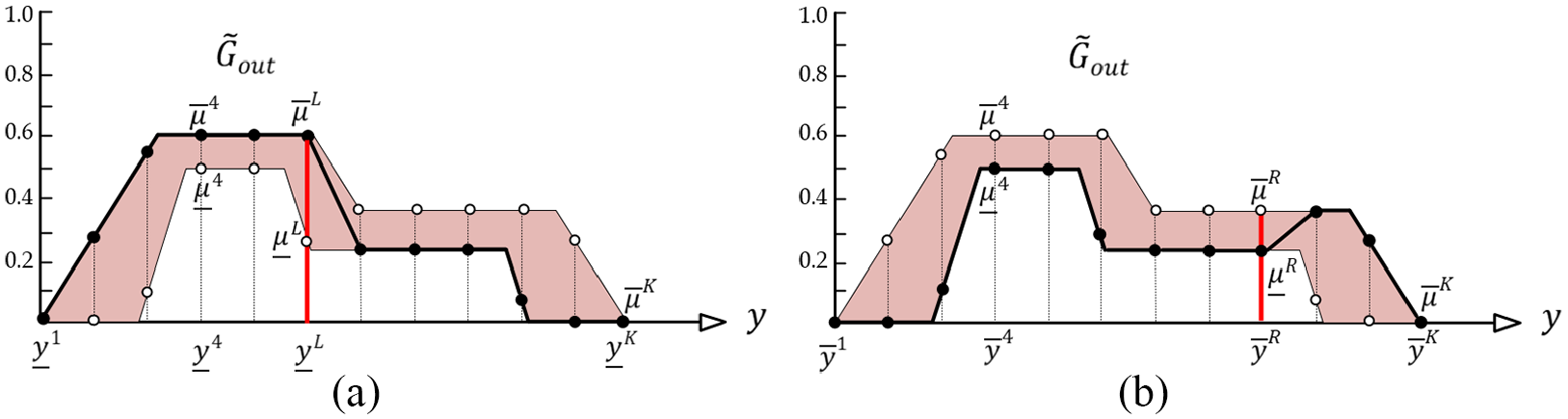
In this operation, all the fired FS must be combined in order to find the crisp value. With this aim, the centroid of a T2 FS must be described as an interval that is a type-reduced set. This work adopts an extension of Type-1 defuzzification method called Karnik-Mendel (KM) algorithm. 37 It has been shown that this iterative algorithm is a TR method with a great accuracy. The TR Centroid begins by the definition of K samples from a T2 FS. The TR method has firstly to obtain two Type-1 FS whose centroid best approximates the upper and lower bounds of the Type-2 FS centroid. Considering the switching points (L, R), Figure 7 illustrates the procedure to find the optimal values.
The candidate points are obtained as follows:
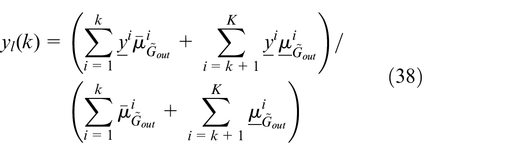
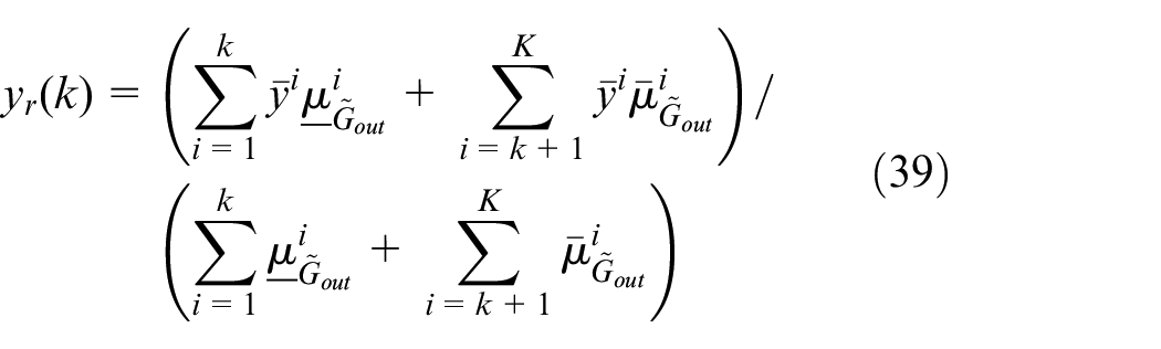
where
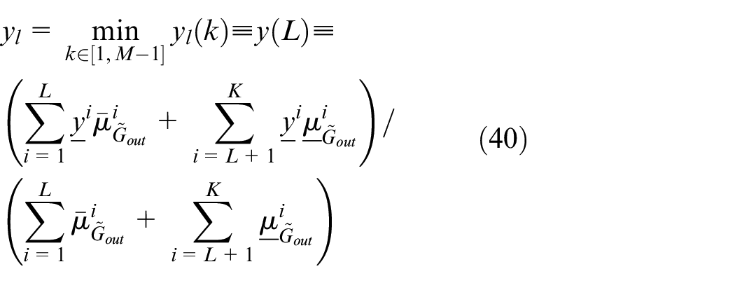
where

Since the approach of the search for centroid candidates (
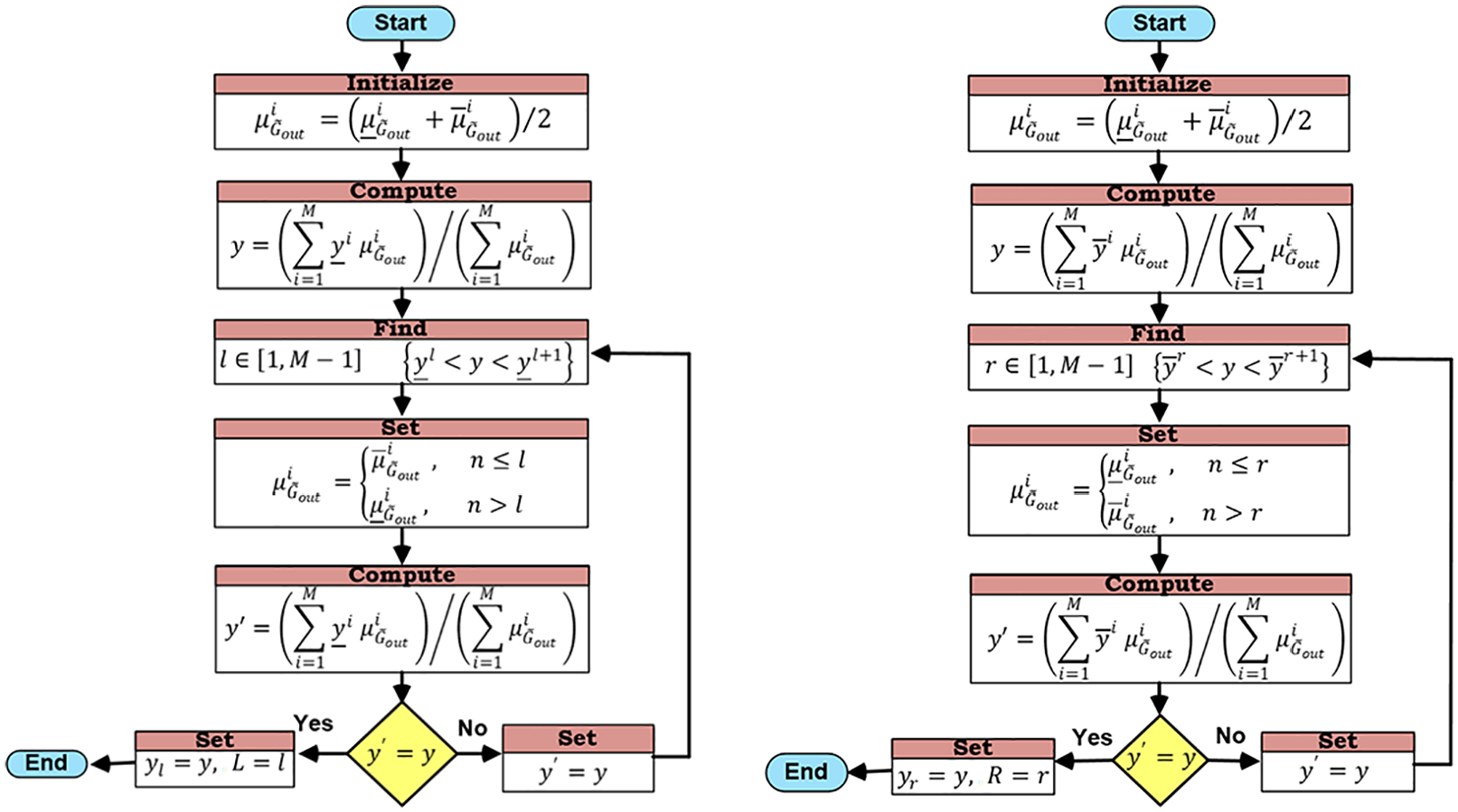
Iterative Karnik-Mendel algorithm.
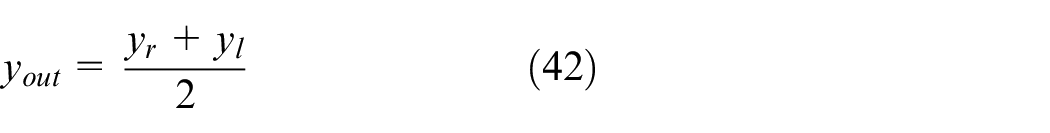
Defuzzification
After applying the TR method, the obtained IFS needs to be converted into a crisp number. However, this step is fairly straightforward, in which the defuzzified value can simply be obtained by calculating the average of the intervals left and right endpoints as follows:
SSO-based IT2FL control of 3-RRR planar Robot
The SSO algorithm takes the assumption that the search space is considered a communal web, the place for the communication of the social spiders. Each solution inside the search space express the position of the spider inside the communal web. A weight, compatible with the fitness value of the solution, is attributed to each spider. There are two variance search spiders in the algorithm: males and females. It starts defining the number of female and male spiders inside the search space. The number

where

Thus, the
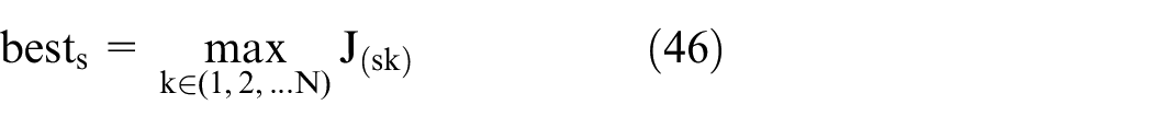
Assignation of fitness
Each spider in the population
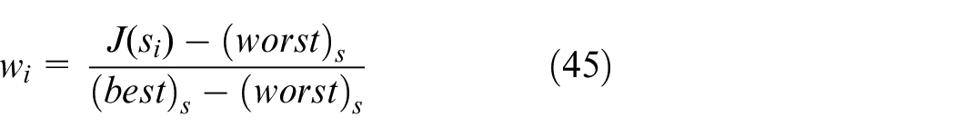
where

Modeling of the vibrations
In the colony, the information among members is encoded based on small vibrations. Such vibrations are employed to initiate the spider and they are related to spider weight and the distance between spiders. The model of the vibration process can be described by;
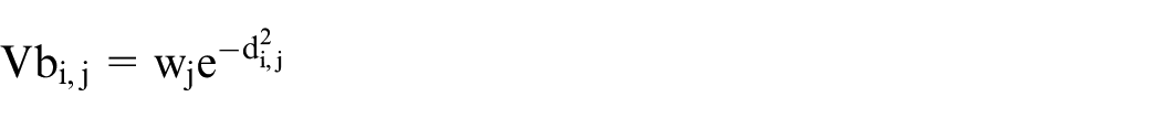
where

Initialization of population
The SSO algorithm is iterative and the complete population (females and males) should be initialized randomly. The procedure is started with the initialization of the position of the N spiders and the set S. The position fi of each female spider (or male mi) is represented by an n-dimensional vector, with parameters values that must be optimized. This value is randomly and uniformly distributed by initial parameters between pre-defined upper (PjHIGH) and lower (PJLOW) bounds, as represented by43,48:
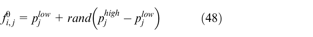
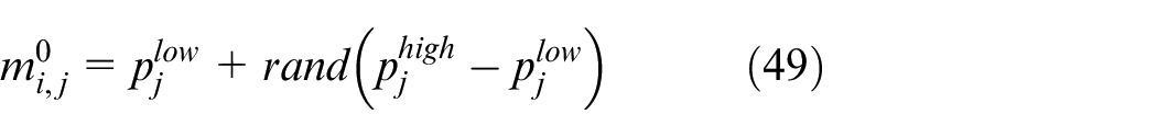
where
Cooperative operator
Female cooperative operator
Female spiders are attracted or repulsed by other spiders, it doesn’t matter their gender, which is generally defined by their vibrations transmitted on the communal net and elements like cycle of reproduction, curiosity, and random phenomena.
The attraction movement is activated if a uniform random number
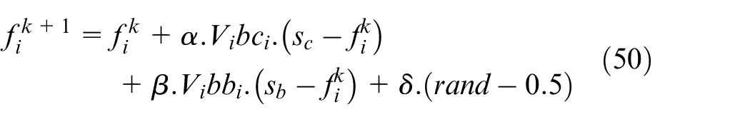
Otherwise, a repulsion movement is generated as
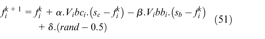
where
Male cooperative operator
The social cooperation has biological features that allows the classification of the spider’s male population into Dominant
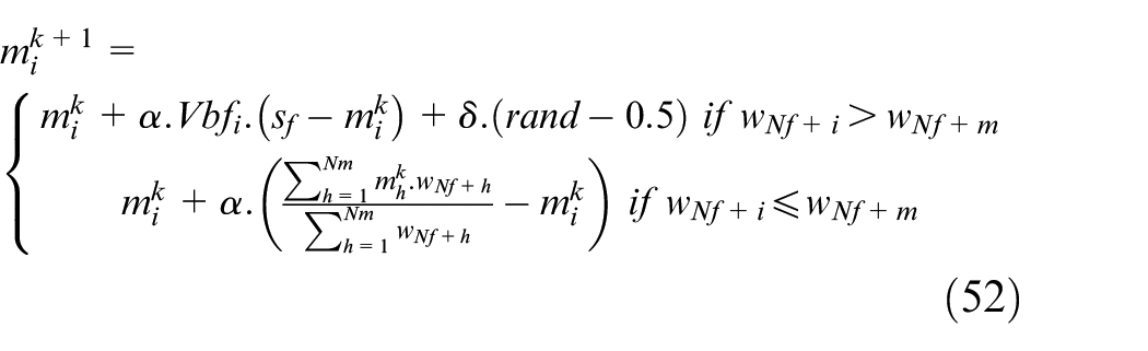
where
Mating operator
Mating in a social spider colony is done through dominant female male members. If the dominant male
One aspect in the mating operation is that each spider involved in the process (elements inside
where i
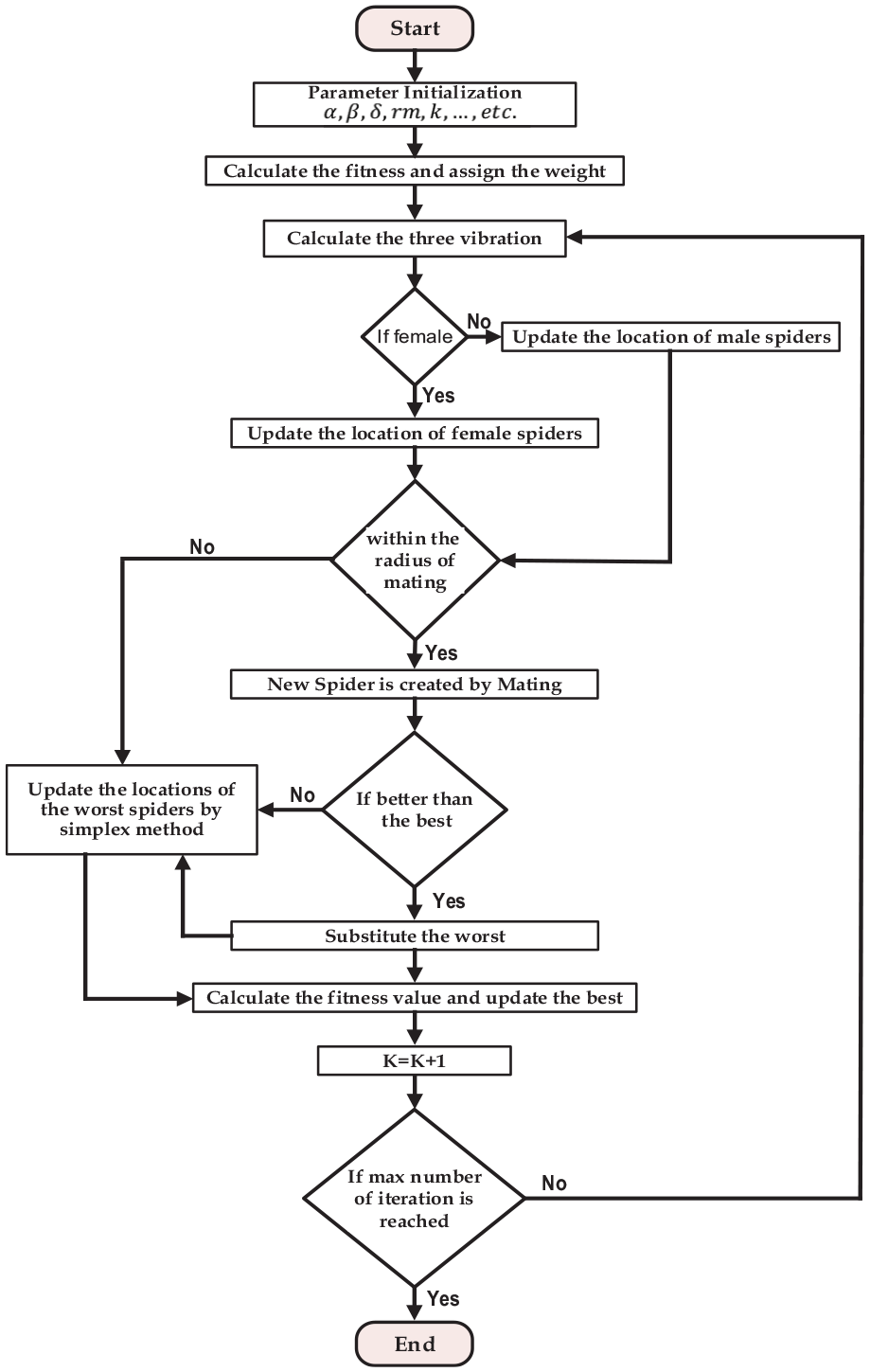
SSO algorithm in a flowchart.
Design of optimal IT2FLC of planar 3-RRR parallel robot
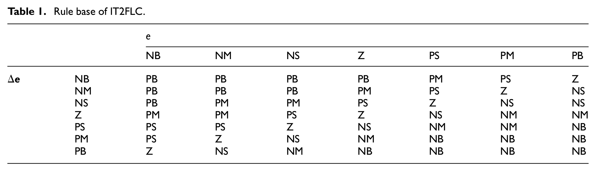
When it comes to the Interval Type-2 PD-Like Fuzzy Logic Controller, it is considered the Mamdani system. So on, it will require seven input-output membership functions of triangular type, as presented in Figure 10. The universe of discourse should be inside the range (−1, 1) for both input and output. The chosen procedure for defuzzification is the Centroid. A rule-base for the proposed IT2FLC is presented in Table 1. A reduction method for the IT2FLC is implemented by the KM algorithm shown in Figure 8.
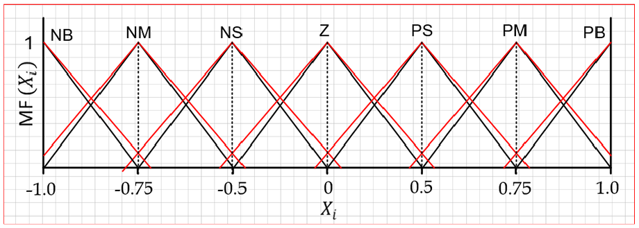
Input/output MFs.
Rule base of IT2FLC.
The SSO algorithm for the optimal tuning of the IT2FLC applied to the 3-RRR parallel manipulator was shown in Figure 11. This algorithm is responsible to tune and optimize nine gains (six inputs and three outputs) of the IT2FLC and also for the T1FLC. The desired positions (
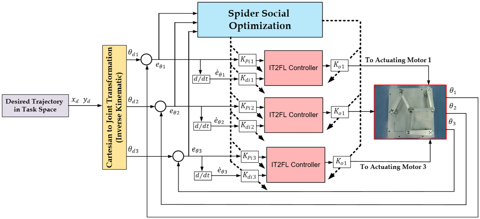
SSO based IT2FLC of planar 3-RRR parallel robot.
Computer simulation
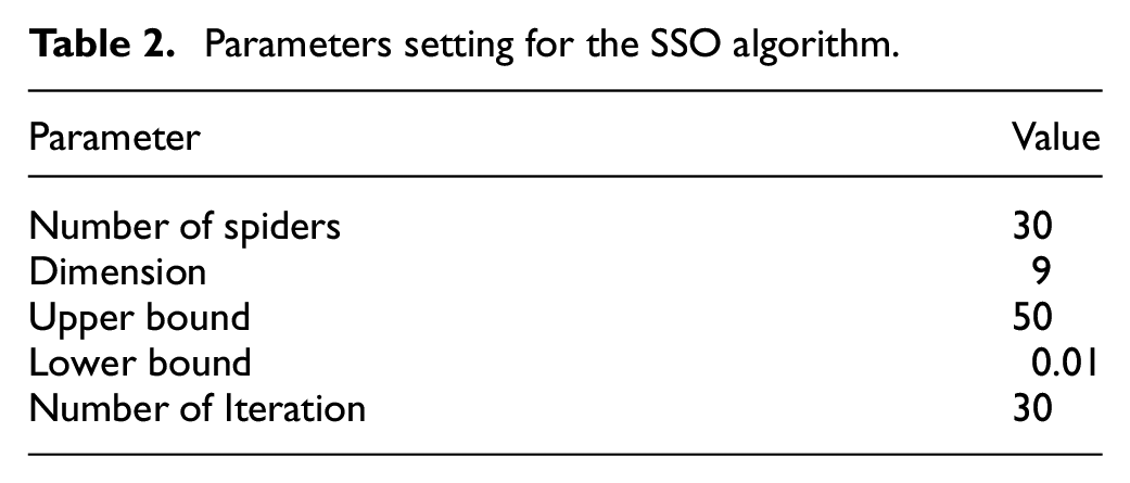
Each controller structure has design parameters related to the SSO algorithm that should be defined by a trial-and-error procedure. However, the tuning criteria is based on the minimization of the tracking error. The MATLAB/Simulink (R2015b) environment was used for the simulations that allowed the examination of the controllers’ effectiveness. These simulations were performed considering a sampling period of 0.5 ms.
The SSO algorithm is dedicated to optimization of the output and input gains of FLC. As it was defined one single fuzzy logic structure for each active joint, the 3-RRR parallel manipulator has three fuzzy logic structures. Each FLC has three gains, which are the Proportional and Derivative input gains and the output gain. So, there are nine gains that the SSO algorithm is responsible to tune, which are the proportional gains (
Parameters setting for the SSO algorithm.
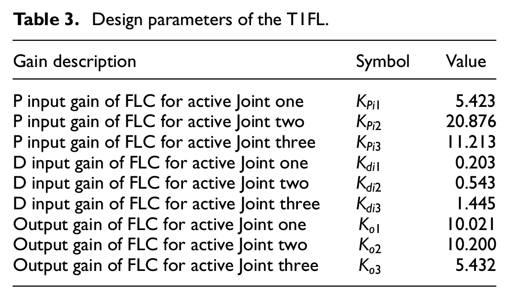
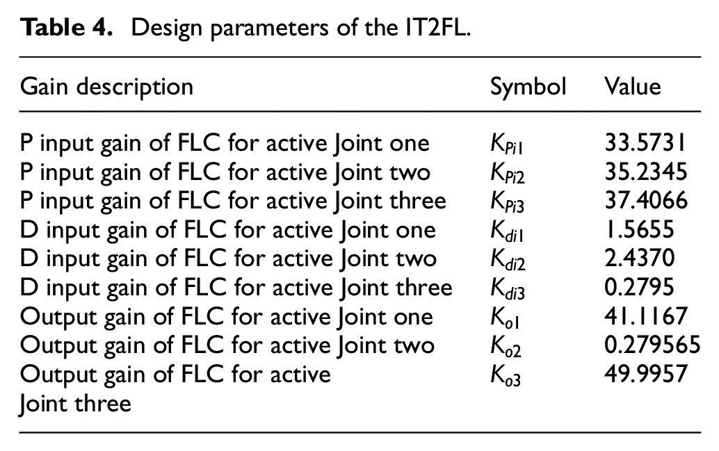
Tables 3 and 4 list the optimal values of total gains for T1FL and IT2FL controllers, which are tuned based on SSO algorithm.
Design parameters of the T1FL.
Design parameters of the IT2FL.
Two scenarios are presented; one for the case of square trajectory without load application and the other with the applied load.
Case I: A square trajectory without disturbance
The steps of robot movement is performed in the following sequence:
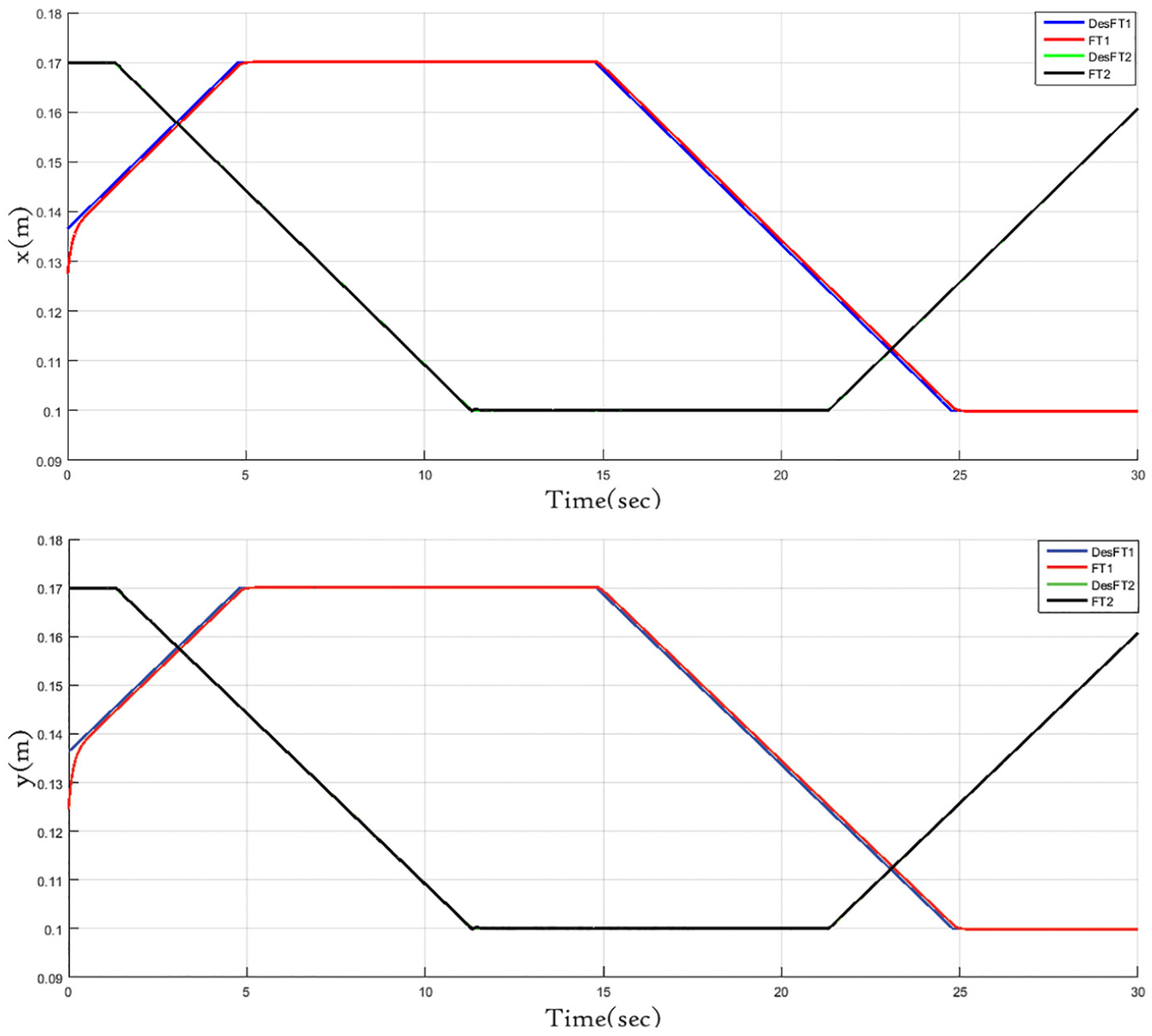
The position of the robot gripper has to move from (0.1, 0.27) to (0.17, 0.27) m, and the end-effector goes from (0.17, 0.27) to (0.17, 0.33) m. So, the center of the gripper goes from (0.17, 0.33) m to (0.1, 0.33) m. Then, the end-effector goes from (0.1, 0.33) m to the initial position (0.1, 0.27) m. However, the initial conditions begins at
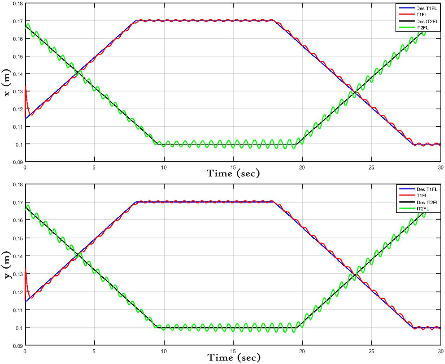
Such a trajectory is suitable for high-velocity and high-acceleration robots. It is commonly adopted in applications in industry, like the assembly of electronic components, cutting by laser, and food packing. With this algorithm, continuity in acceleration is assured when dealing with robots of high-speed. Figure 12 illustrates the desired and actual trajectories along
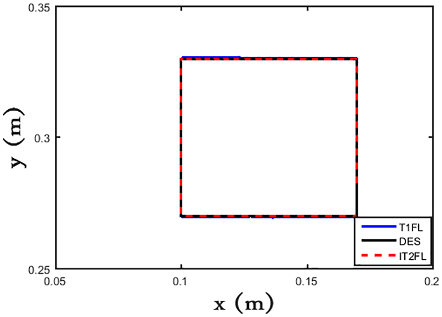
View of the desired square trajectory in the
Trajectory tracking of end effector Cartesian positions
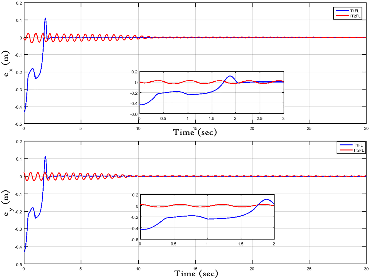
The Cartesian errors
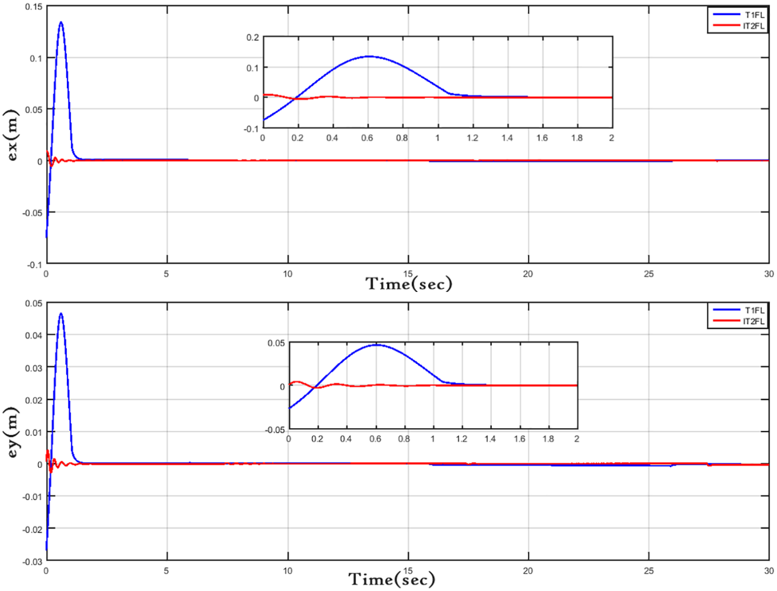
Cartesian position errors
The performance in Cartesian space of T1FL and IT2FL controllers can be evaluated by the Root Mean Square Error (RMSE). The controller with the smaller RMSE value is considered the best one. The calculation of the RMSE in Cartesian space is given by:
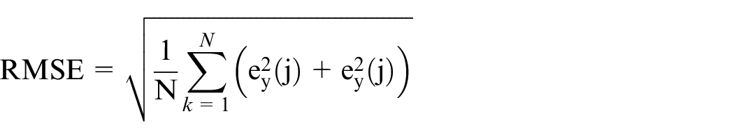
This RMSE value can be rewritten as:
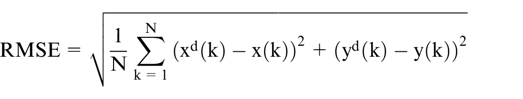
being
RMSE values in Cartesian space for IT2FL and T1FL controllers.
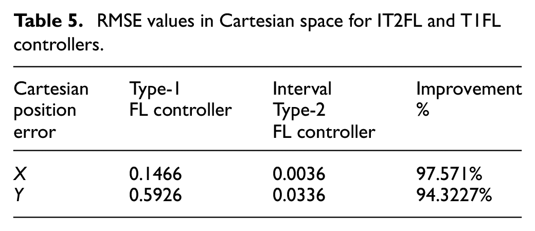
The resulting RMSE values along the x and y axes are much better for the IT2FL controller when it is compared with the T1FL controller, as it is presented in Table 5. On the x axis, there is an improvement of 97.571%, while on the y axis the improvement is of 94.3227%.
The errors
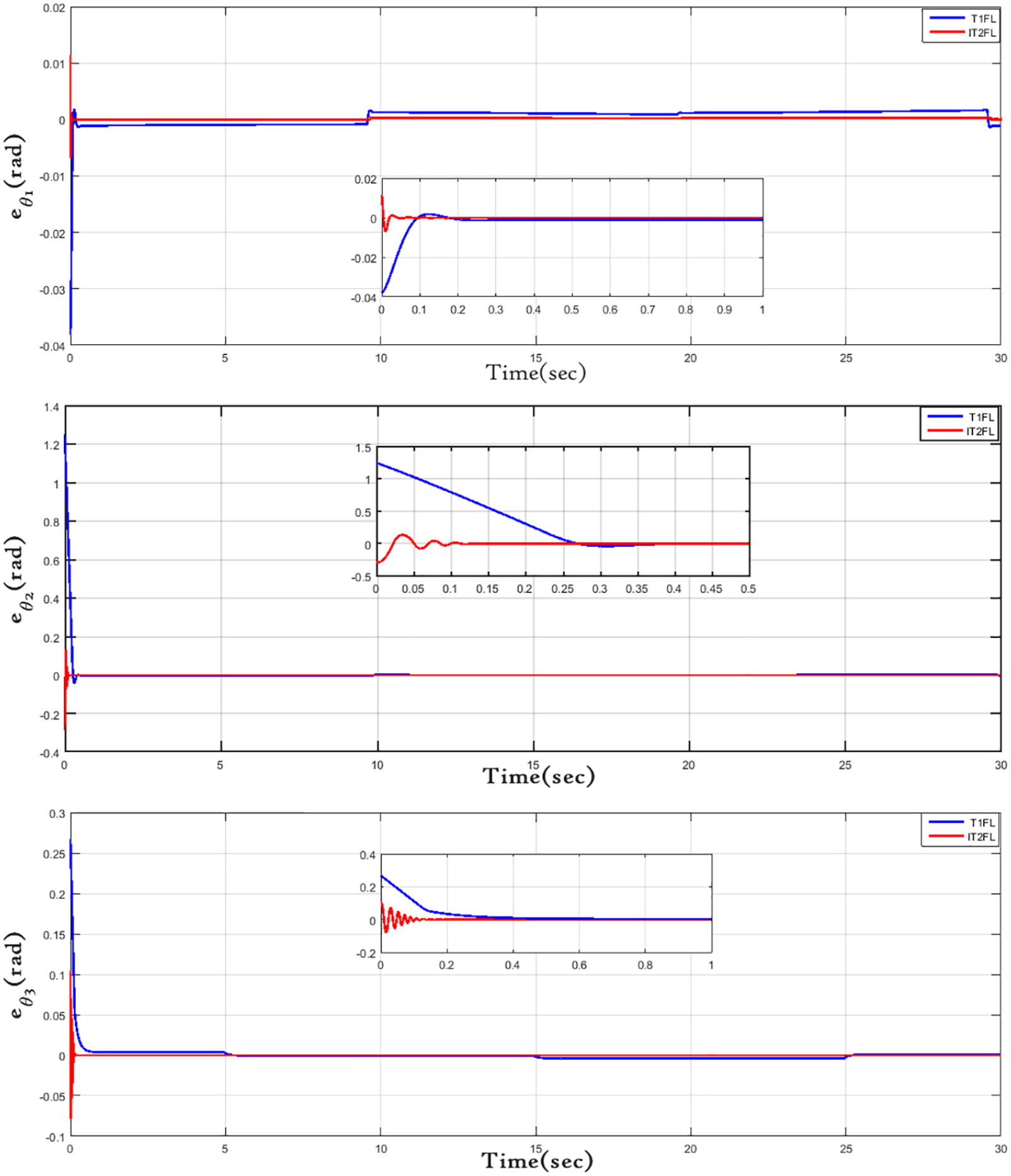
Joints errors of active joints based on T1FL controller (blue-colored line) and IT2FL controller (red-colored line).
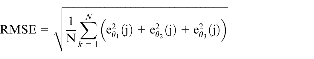
This RMSE value in joint space can be rewritten as:
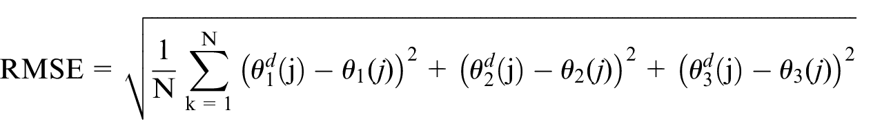
being
The RMS values of errors in joint space resulting from T1FL and IT2FL controllers.
In joint space, the IT2FL controller provided better performance in terms of RMSE values, as it can be clearly seen in Table 6. The RMSE values for the T1FL controller are high and there is a significant improvement when the IT2FL controller is considered. So, in both joint and Cartesian spaces, it can be concluded that the tracking performance is better for the IT2FL controller than for the T1FL controller.
The control signals, represented by the torques of the three actuator motors, are presented in Figure 16. Considering the same task for the system, first with the T1FL controller and then with the IT2FL controller, it can be clearly seen in Figure 16 that the IT2FL controller required a smaller torque than the T1FL controller. This means that the control effort provided by the IT2FL controller was smaller for a same task.
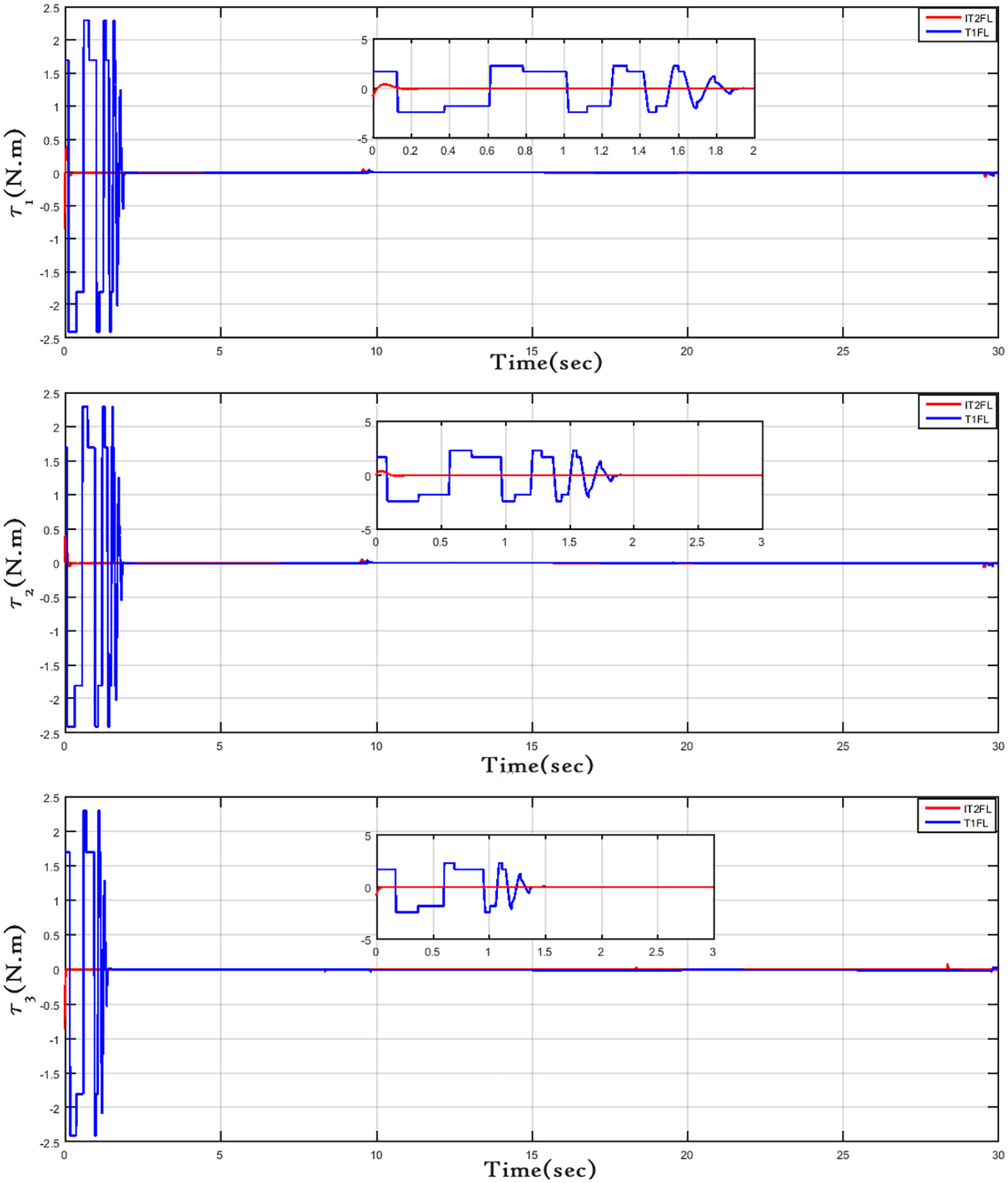
Torque responses actuated by parallel robot motors due to T1FL and IT2FL controllers in joint space.
Case II: A square trajectory with disturbance
The steps of robot movement is performed in the following sequence:
The position of the robot gripper has to move from (0.1, 0.27) to (0.17, 0.27) m, and the end-effector goes from (0.17, 0.27) to (0.17, 0.33) m. So, the center of the gripper goes from (0.17, 0.33) m to (0.1, 0.33) m. Then, the end-effector goes from (0.1, 0.33) m to the initial position (0.1, 0.27) m. However, the initial conditions begins at
For this case, the robustness to external disturbances will be considered in the performance evaluation. So, a harmonic torque disturbance given by
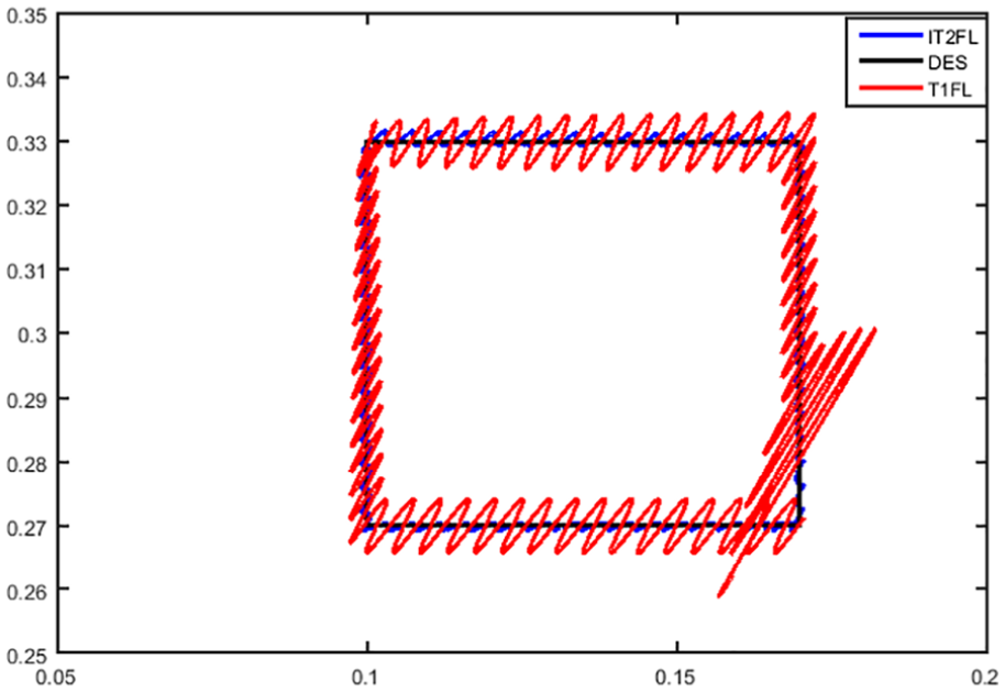
Top view of the desired square trajectory in the x-y plane with disturbance.
The actual and desired trajectories in a square are presented in Figure 18, for the system with both T1FL and IT2FL joint controllers under effect of external harmonic disturbances. It can be seen that, under disturbances, the IT2FL controller provided a transient response that remains relatively smooth and unchanged in terms of tracking, whereas the transient response with the T1FL controller is highly rippled and distorted. This primary analysis indicates a more robust IT2FL controller than the T1FL controller.
Trajectory tracking of end effector Cartesian positions
The position errors in Cartesian space,
Cartesian position errors
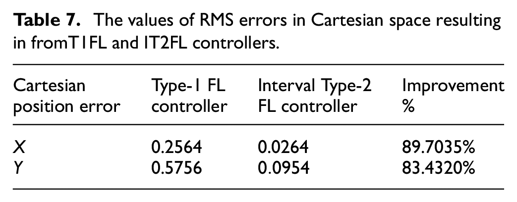
The values of RMS errors in Cartesian space resulting in fromT1FL and IT2FL controllers.
The errors
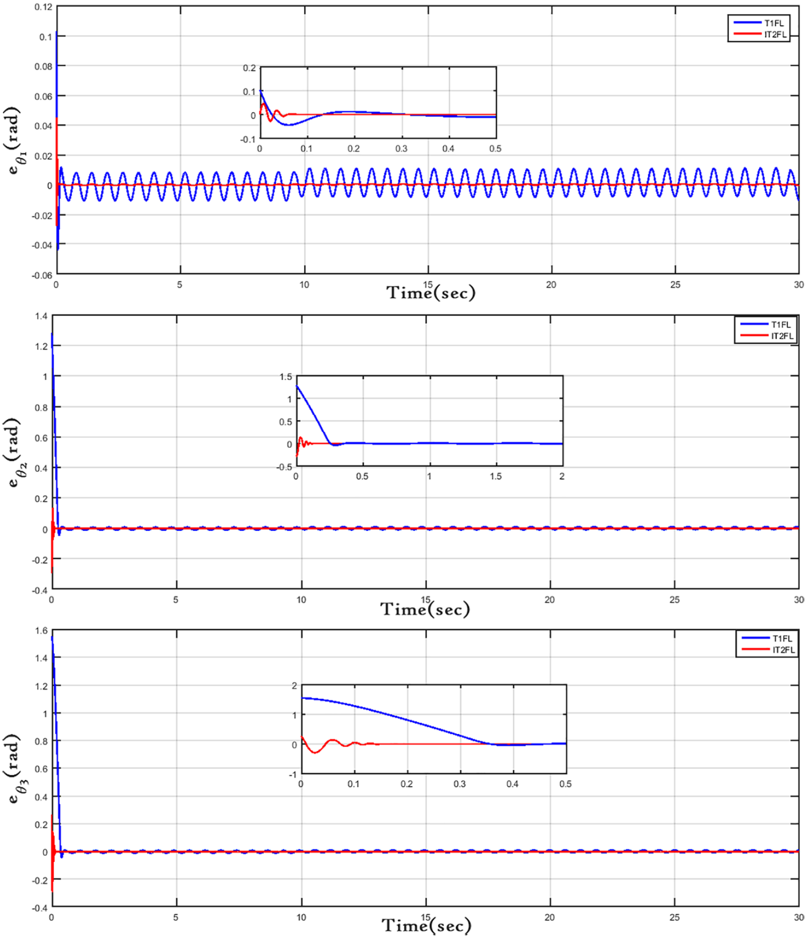
Position and joints errors based on T1FL controller in joint space (blue line) and IFT2 controller in joints (red line).
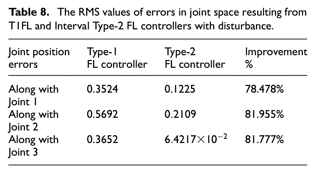
The RMS values of errors in joint space resulting from T1FL and Interval Type-2 FL controllers with disturbance.
The control signals, represented by the torques of the three actuator motors, are presented in Figure 21. Considering the same task for the system, first with the T1FL controller and then with the IT2FL controller, it can be clearly seen in Figure 21 that the IT2FL controller required a smaller torque than the T1FL controller. This means that the control effort provided by the IT2FL controller was smaller for a same task.
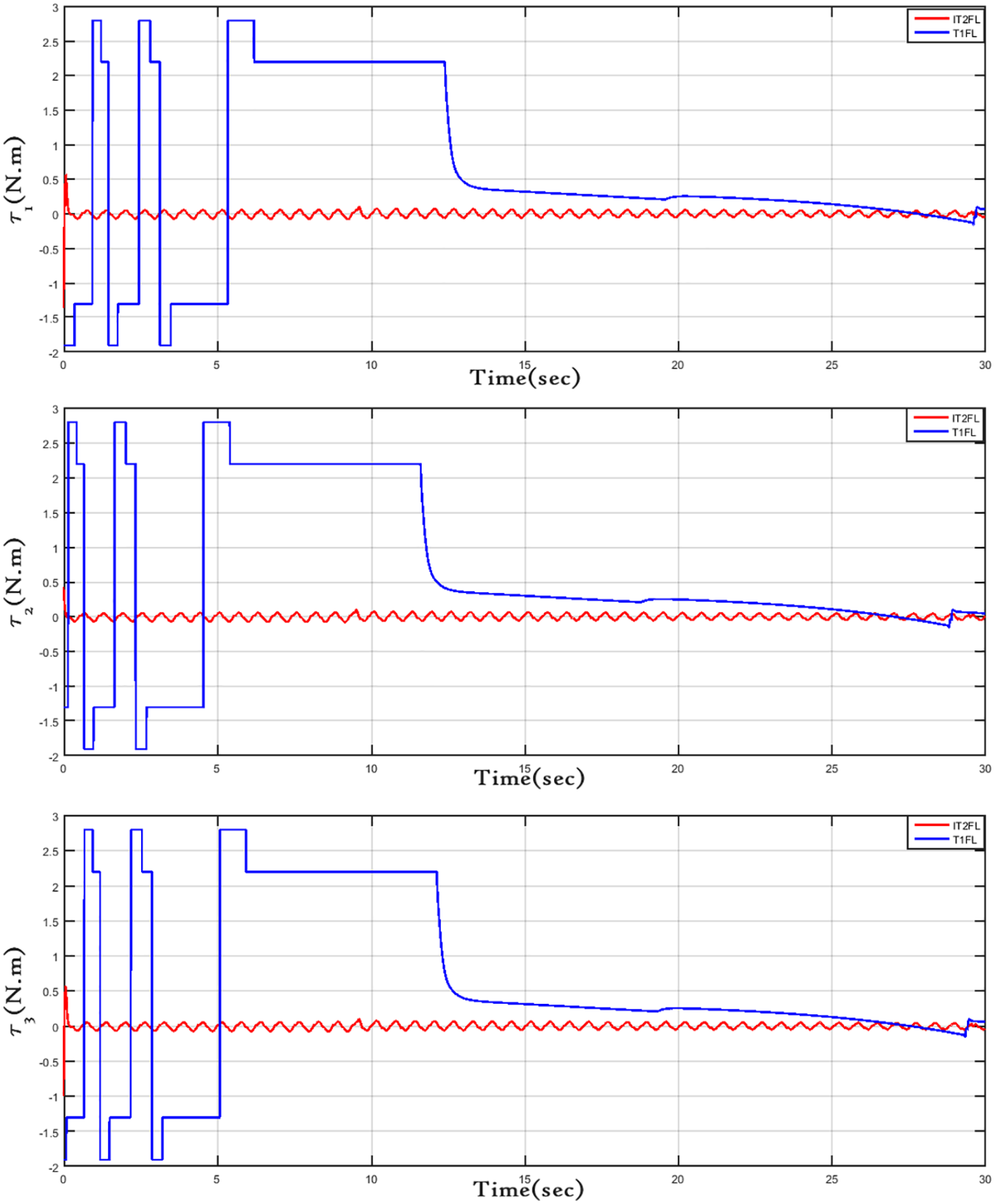
Torque responses actuated by robot motor due to T1FL and IT2FL controllers in joint space.
Conclusions
It has been shown that the SSO algorithm is a viable alternative for the optimal tuning of PD design parameters in both T1FL and IT2FL controllers, avoiding traditional time consuming and tedious trial-and-error procedures. Moreover, it was verified that this optimization strategy confirms that, in general, the IT2FL controller provides better results than the T1FL controller.
Considering no exogenous disturbance, it was achieved a better performance, in both joint and Cartesian spaces, with the IT2FL controller when compared with the T1FL controller. Moreover, the control efforts, in terms of torque, are smaller for the IT2FL controller in comparison with the T1FL controller.
When exogenous disturbances are considered, the simulations presented that a better tracking behavior was achieved, in terms of RMSE, with the IT2FL controller when compared with the T1FL controller. Also, the IT2FL controller provided lower control effort and presented more robust characteristics than the T1FL controller.
This study can be implemented in real-time to verify experimentally the effectiveness of proposed controller. In addition, other extension of the work can be made by including other optimization techniques for the sake of comparison.49–55 Cooperative control can be developed for this type of 3-RRR planar parallel robot for the surgical application.12,14,56
Footnotes
Authors’ Note
Ahmad Taher Azar is also affiliated with College of computer and Information Sciences, Prince Sultan University, Riyadh.
Declaration of conflicting interests
The author(s) declared no potential conflicts of interest with respect to the research, authorship, and/or publication of this article.
Funding
The author(s) received no financial support for the research, authorship, and/or publication of this article.