
Abstract
Achieving port automation of machinery at bulk terminals is a challenging problem due to the volatile operation environments and complexity of bulk loading compared to the situations in container terminals. In order to facilitate port automation, we present a method of hull modeling (reconstruction of hull’s structure) and operation target (cargo holds under loading) identification based on 3D point cloud collected by Laser Measurement System mounted on the ship loader. In the hull modeling algorithm, we incrementally register pairs of point clouds and reconstruct the 3D structure of bulk ship’s hull blocks in details through process of encoder data of the loader, FPFH feature matching and ICP algorithm. In the identification algorithm, we project real-time point clouds of the operation zone to spherical coordinate and transforms the 3D point clouds to 2D images for fast and reliable identification of operation target. Our method detects and complements four edges of the operation target through process of the 2D images and estimates both posture and size of operation target in the bulk terminal based on the complemented edges. Experimental trials show that our algorithm allows us to achieve the reconstruction of hull blocks and real-time identification of operation target with high accuracy and reliability.
Introduction
As the world economics develops, maritime transportation flourishes and accordingly the demand in capacity of port increases. In order to deal with the increasingly huge volume of transportation, more and more ports attach great importance to the automation at port terminals. Unmanned cargo loading system is a significant constitute of port automation. Therefore, a lot of researchers and engineers focus on developing advanced measurement systems and intelligent control systems for automated cargo loading system and a significant amount of related technologies and methods1,2–6 have come up and been applied to facilitate port automation at container terminals. However, compared to rapid development of automated loading system for container ships, the degree of automation in bulk terminals is still low and develops slowly due to the complexity of bulk cargo loading and volatile operation environments. The specification of cargo containers are standard, while shapes of bulk hatches vary a lot according to different structures and capacity of bulk ships. Thus, it is challenging to design one automatic loading system which can undertake the loading task for all the bulk ships with different structures. Currently, bulk ship loading still highly relies on manual operation of loading machine drivers, hatch conductors and loading instructors in most of bulk terminals. Two significant problems need to be solved in order to achieve automated loading operation at bulk terminals and so far, researchers have done some exploratory and enlightening work.
Firstly, a reliable measurement system and an algorithm of bulk ship modeling are necessary for acquiring 3D hull structure of bulk ships, especially the detailed structure of hulls under operation. The main stream of sensing modules for measuring ships structure includes 3D depth cameras and lidars, which describes 3D structure of entities in terms of point cloud while the modeling algorithms are varied.2–8 As cargo ships are often large and the horizon of those sensors have limits, sensors often need to scan different pieces of cargo ships and then put the sectional scanned point clouds together to model the structure of the whole hull blocks. In Guan et al., 9 present an automatic registration method of hull blocks based on given CAD model of ships. They use principal component analysis (PCA) for rough registration and then refine the result through iterative closest point (ICP) algorithm. Their method works efficiently but it requires ships’ CAD model as reference to register those sectional measured point clouds, which makes it inapplicable when ships CAD models are not accessible due to common reasons like confidentiality. In Xi-Liang et al., 7 present a reconstruction method based on a single-wire Laser Measurement System (LMS) and a single axis rotating servo mechanism. The measurement system is mounted on the loader above the middle of cargo ship. The servo mechanism drives the LMS rotating so that LMS can scan from one end of ships to the other, as the position of the LMS is fixed in 3D space and it can acquire point cloud of only one sector once a scan. Then, the hull structure can be built by combining point clouds of different slices of ships cross sector collected by the LMS with different directions. However, the drawback of this method lies in that it cannot acquire complete structure of hull blocks especially the ships hatches because the LMS undertakes the measurement from only one position and thus the edges of hatches can be easily sheltered by the lid of hatches. As a result, the effectiveness and accuracy of the method in recognition of bulk cargo holds are undermined. In Mi et al., 8 use four single-wire LMS mounted on the loader above bulk ships. Compared with the method in Xi-Liang et al., 7 instead of using only one LMS fixed at one position, they use four LMS scanning linearly from above ship’s bow to stern and merge point clouds measured by multiple lidars at different positions and rebuild ship’s structure by registration of point clouds. However, they use the ratio of loaders moving speed to the LMSs scanning frequency as interval between coordinates of point clouds of adjacent cross sections and register the adjacent point clouds directly with the estimated interval. Using the roughly estimated interval as final transformation for registration can result in inescapable errors in ship’s reconstruction. That’s because the instant scanning frequency of LMS can often be different with the designated value and the estimation of the loaders speed also has errors. Whats more, the method does not consider ship’s movement caused by tide or other outer forces, which also jeopardizes the accuracy of reconstruction modeling.
Second problem to be solved is the real-time identification of operation targets. If the position and size of bulk cargo holds within the operation zone are identified in real time, it would greatly facilitate the loader to locate and load bulk materials into holds automatically. In Xi-Liang et al., 7 achieve the identification by transforming the 3D point cloud into 2D image and processing the image for identification of cargo holds. They project the point cloud of hull blocks to XOY plane (considered as the horizontal plane) as an 2D image and the pixel values of the image represents the Z coordinates value of original points in the point cloud. They distinguish zone in the deck from zone in the holds by setting a height threshold of pixel values, as they assume that Z coordinate values of points in the holds are always lower than the height of coastline while the values of points in the deck are higher. Then, they use a seed rectangle which starts in the corner of cargo hold and grows until it reaches borders of the two different zones mentioned above and the grown seeding rectangle is recognized as the operation target. In Mi et al., 8 apply similar projection method but use a different recognition algorithm. They project the 2D images into both X and Y coordinates and record how many pixels of points in the deck zone are at each X and Y coordinate value respectively. By setting a threshold on the number of pixels of points in the deck zone, their algorithm can detect the rising edges and falling edges of the 1D pixel value, and thus the position of borders between hold zones and deck zones are estimated and the position and size of holds under operation are identified. Methods in Refs.7,8 work efficiently and provides enlightening thoughts of achieving automation in bulk terminals. However, their identification algorithms are not technically real-time. In order for the dynamic identification, their systems have to scan the whole hull blocks every time before the identification. That’s because their identification algorithms are completely based on the knowledge of ship structure of the whole hull blocks. What’s more, their methods are based on several unwarranted assumptions, which makes it difficult to apply those methods in the volatile operating conditions of real cases:
The plane of bulk hold’s hatch is assumed parallel to XOY plane in lidar’s coordinate. However, a lot of factors in real operation cases like tide and the uneven distribution of cargo materials in the hold can makes this assumption invalid and thus cause distortion of hatchs size and position in the projection of the 3D structure to the XOY plane;
It is assumed that the height of the point cloud in the hold zone is significantly lower than the cost line and the deck, which is not necessarily true when the holds are highly loaded with a huge volume of materials;
The borders of hold hatches is assumed parallel or perpendicular to the X coordinate. But such a condition isnt met when bulk ship berths with its main axis not strictly parallel with the coastline of the port.
In summary, in order to facilitate the automation at bulk cargo terminals, it is necessary to reconstruct the 3D structure of hull blocks and then achieve identification of operation targets in real time. Current solutions to part of these two problems provide enlightening insights and exploratory examples but have disadvantages in terms of practicability, accuracy and capabilities of adapting to volatile operating environments in bulk terminals. The main contribution of this paper is concluded as follows:
A moving scan and hull modeling system is established, which can reconstruct structure of the whole hulls in an accurate and integrated way compared with existing techniques.
A novel algorithm of identifying operation targets is presented, which can achieve the real-time recognition of bulk hatches with high accuracy in volatile operating situations.
Hull reconstruction system
This section describes our laser measurement system which can scans cargo ship from ship’s stern to bow and capture 3D structure information of the whole hull blocks and our reconstruction algorithm which can merge all the 3D information to rebuild the 3D model of the whole ship.
Moving-scan lidar measurement system
Our system used a multi-wire lidar (Livox Horizon, developed by DJI) with a field of view (FOV) of 81.7° horizontally and 25.1° vertically. Compared with the single-wire LMS used in Refs.,7,8 the lidar with large FOV allows us to collect information of hull structure with more details and higher resolution. The lidar is mounted on the loader, facing toward berth of bulk cargo ship but not vertically. In order to measure the structure of the whole hull blocks, the lidar with loader moves straightly from above ships stern to the bow at a uniform speed (0.5 m/s in our experiment) along the rail on bulk terminal. The lidar scans 10 times a second, which is enough to collect details of structure of the operation targets for identification. The system is shown in Figure 1, with the red rail, green loader, blue bulk ship, purple lidar and its pink FOV.
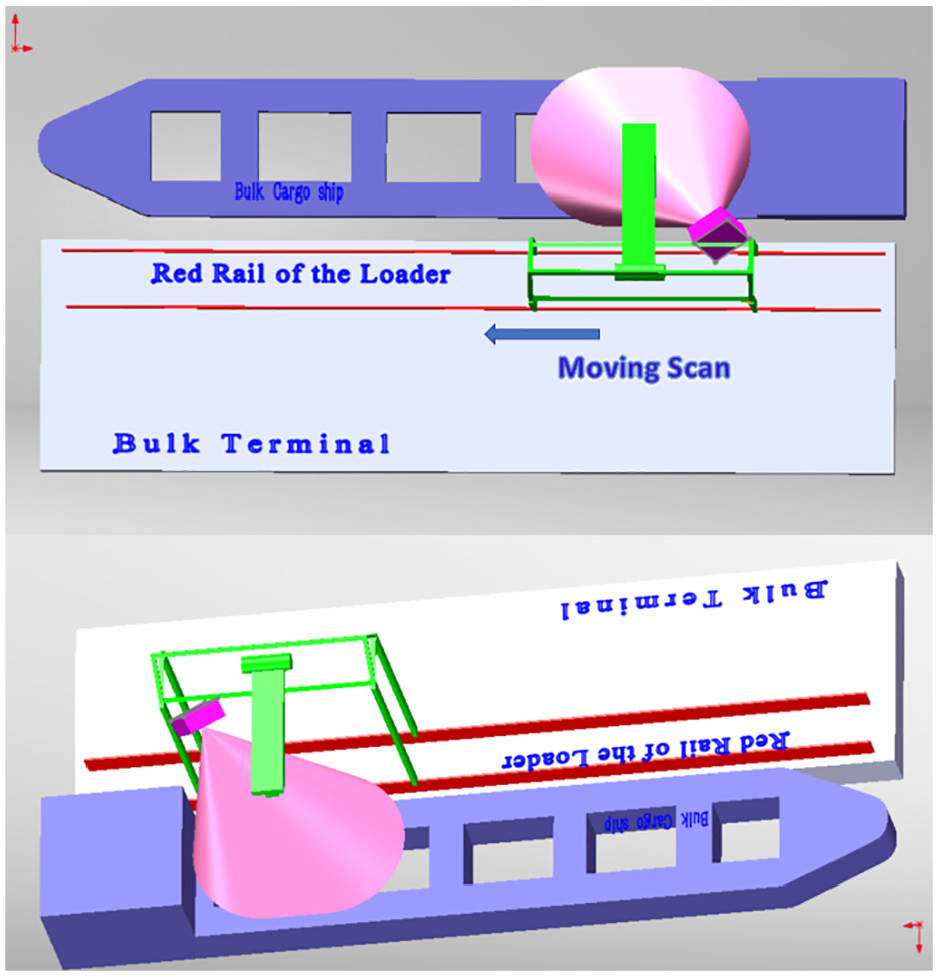
Moving-scan lidar measurement system.
Hull reconstruction algorithm
The output of the above measurement system consists of point cloud streams in 10 frame per second. Among the streams, two timely adjacent point clouds are also spatially adjacent. However, coordinates of the two are not coincident due to the movement of lidar and change in ships posture when scanning. In order to acquire the structure information of the whole ship, we incrementally register pairs of point clouds to the coordinate of the point cloud of the first frame.
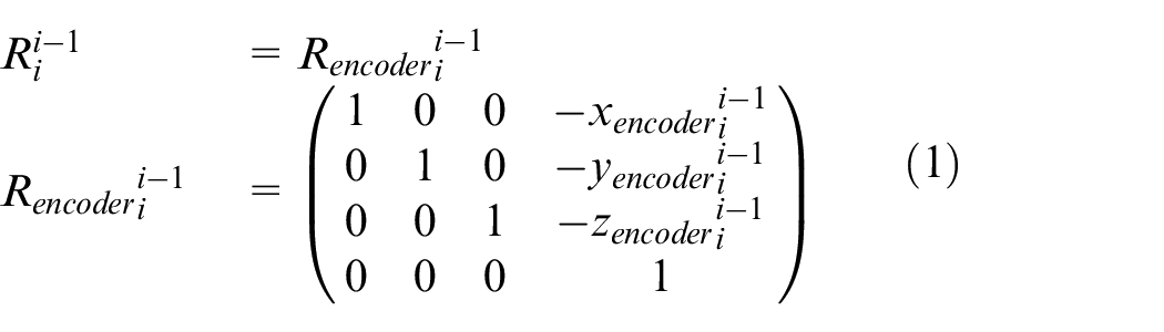
To achieve that purpose, we register each pair of adjacent frames, calculate the transformation matrix of coordinates of the two frames. As the difference between two coordinates is mainly caused by the movement of lidar, we do the rough registration first with the estimation of translation movement based on the data of encoder on the loader which can estimate the position of the loader.

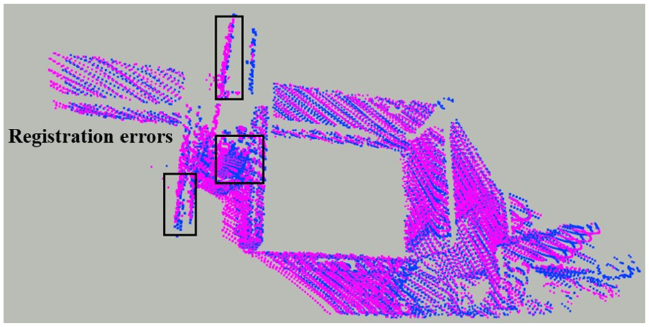
Though the roughly registered point cloud is closely coincident with the former-frame point cloud, as shown in Figure 2, due to the error of data in the encoder and the potential movement of ship during scanning, rough registration is not precise enough to reconstruct the structure of hull blocks of high accuracy: such small errors can accumulate when the transformation matrixes of adjacent frames are multiplied and result in great divergence between point clouds of same part of hull block. Therefore we do the refined registration. With the special scanning mode, Livox Horizon lidar produce the point clouds of the same part of the hull structure with different points and point density at different scanning positions. And thus we need to use the Fast Point Feature Histograms (FPFH)
10
for feature matching in order to acquire refined transformation matrix between
As the calculation of FPFH is computationally expensive, we only calculate the FPFH of key points of those adjacent point clouds. In order to choose key points, we calculate the normal of each point

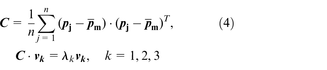
The estimated normal at
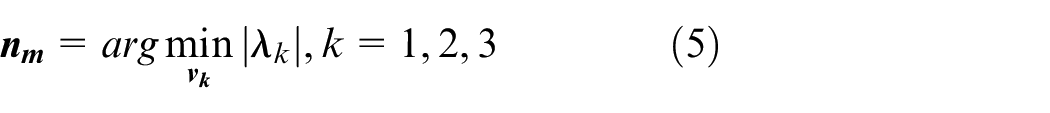
By setting a
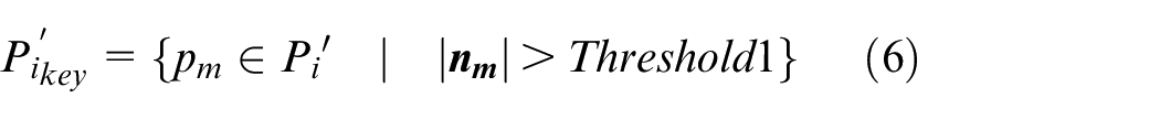

Then we calculate FPFH of each point of
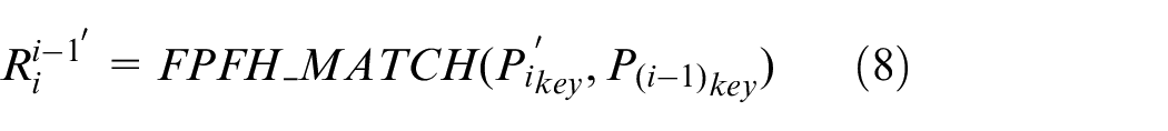
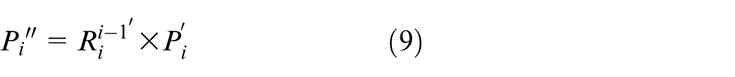
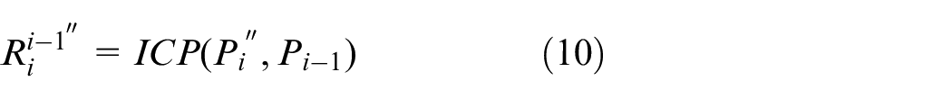
To further refine the registration, we use ICP algorithm 11 to acquire further refined transformation matrix:
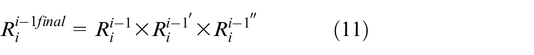
Through above algorithm, we have the final transformation matrix of adjacent frames:
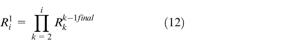
By multiplying those adjacent matrixes from
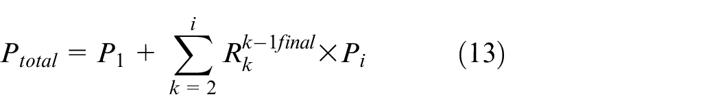
Figure 3 show the whole structure of a bulk ship registered by our algorithm. As shown in the figure, the ship’s bow is only partially reconstructed, and that’s because of the limit of lidar’s FOV and range of loader’s movement. However, it does not affect the identification of operation targets since all the structure bulk holds is scanned and rebuilt.
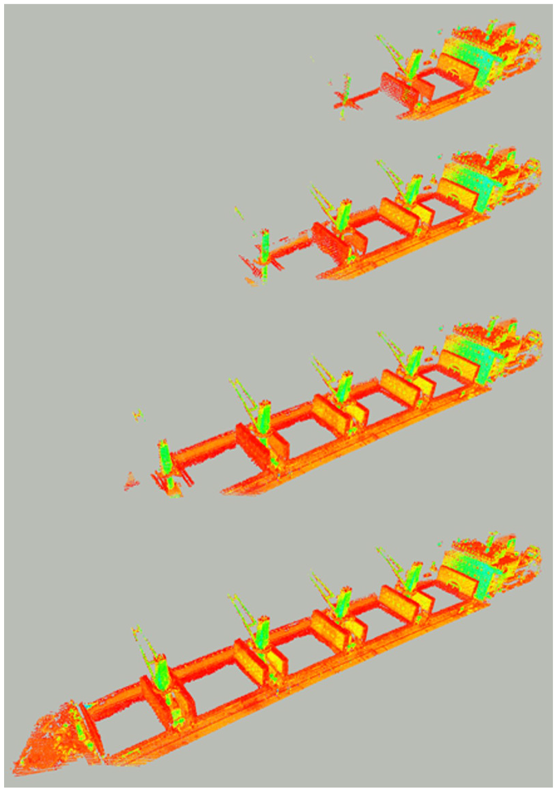
Example of our reconstruction algorithm.
Identification of operation targets
This section describes our algorithm of identifying the operation targets based on the real-time point clouds of operation zones and the bulk cargo ships 3D structure built above. Once the reconstruction of the hull blocks structure is finished, the LMS moves to operation zones and collects real-time point clouds of those zones. By processing those point cloud streams and using the built 3D structure a reference, our algorithm identifies the size and posture of operation targets and thus the slip barrel in the loader can be guided to load bulk materials into the ships bulk holds automatically. In our framework, we apply classical image processing methods instead of machine learning method because as mentioned before, bulk terminals have to load various kinds of bulk cargo ships with different structures and there is not enough qualified dataset for us to build up some framework of artificial Intelligence for target identification of all those different kinds of ships.
Dimensionality reduction of 3D point cloud
Identification of operation targets relies highly on detection of four edges of the bulk ships hatch which is rectangular. Meanwhile, as points of the 3D point cloud are not well structured spatially like 2D images, detecting the four edges directly from the point cloud is difficult and computationally expensive. Thus, the 3D point clouds need to be transformed to 2D images for fast and precise target identification in real time. It is a natural thought to project the point cloud to the deck or horizontal plane, as in Refs.7,8 However, as the posture of ships can change due to tide and uneven distribution of materials in the holds, the deck plane is often not coincident to the horizontal plane and the plane coefficients are difficult to be estimated. Thus, we use the method presented in Steder et al. 12 Instead of plane projection, we project the point cloud to spherical coordinate and transform it to a 2D image.
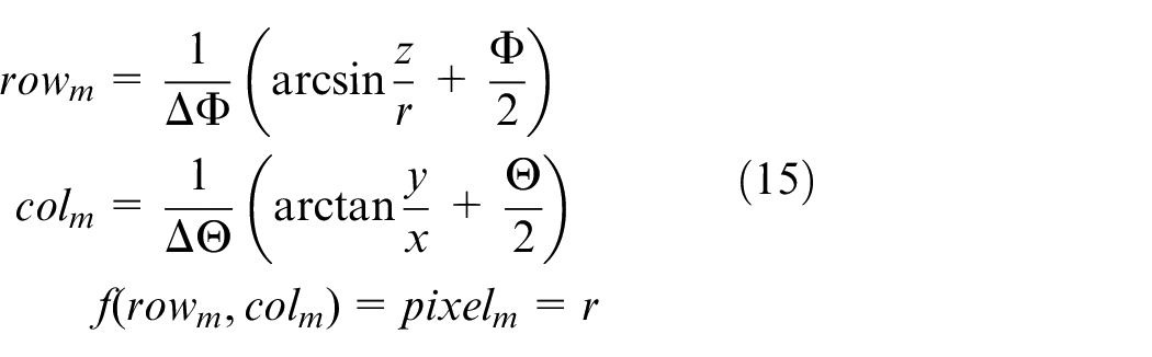
For points in 3D space, their coordinates are defined as
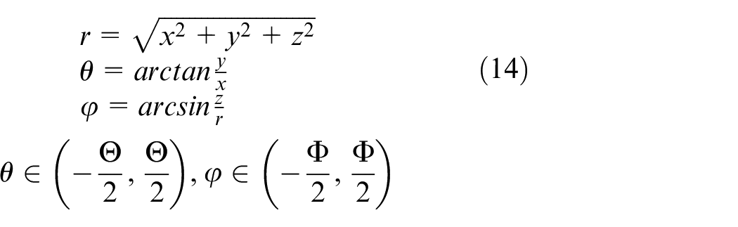
The angular resolution is set as
The advantage of spherical projection lines in that compared to plane projection, no matter what posture of bulk ship relative to lidar is, points of point cloud do not overlap and information of shup’s structure will not be lost during project. Figure 4 show a frame of point cloud of the operation zone and its projected 2D image.
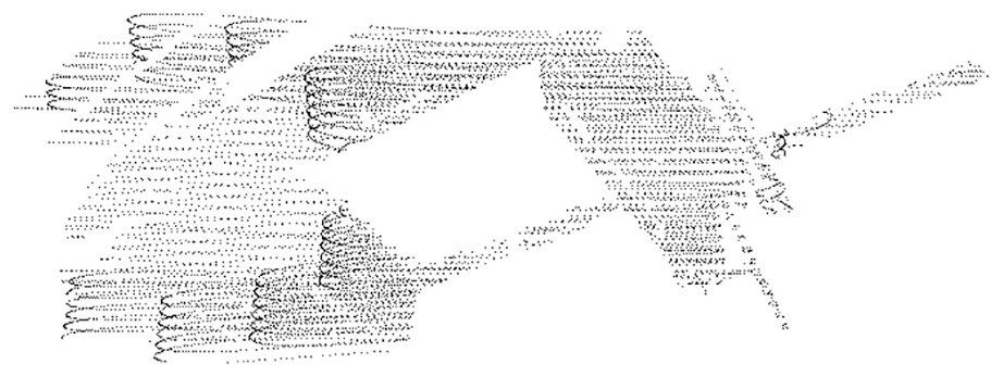
Example of projected.
Identification of operation targets
As the operation targets are rectangular, the core of identifying those targets lies in detection of four edges of the rectangle. To achieve that purpose, our algorithm convolves the 2D images with Canny edge detect filter.
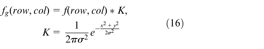
Firstly, we apply Gaussian filter for denoizing:
Then the gradient of the filtered image
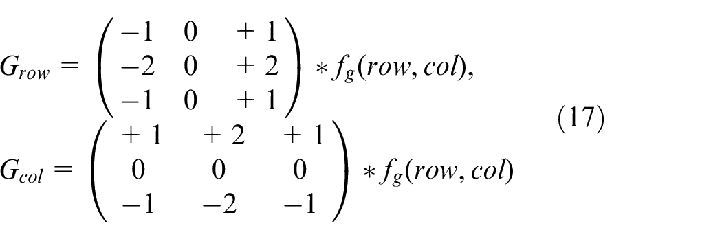
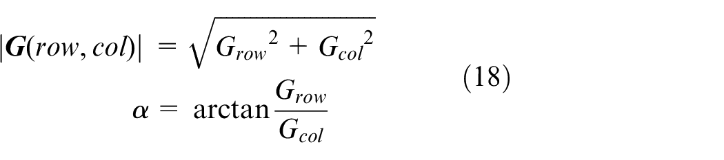
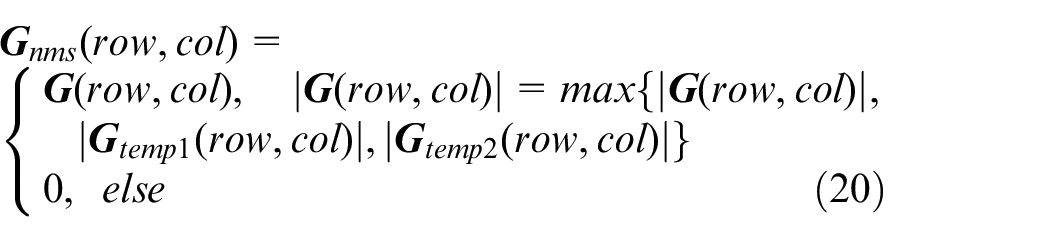
Then we apply Non-Maximum Suppression to
After that, we apply Non-Maximum Suppression for refined edge detection:
By setting a
Then, we use the method presented in Suzuki and Abe
13
and extract the edges of operation target based on
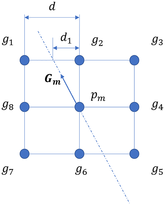
Non-maximum suppression.
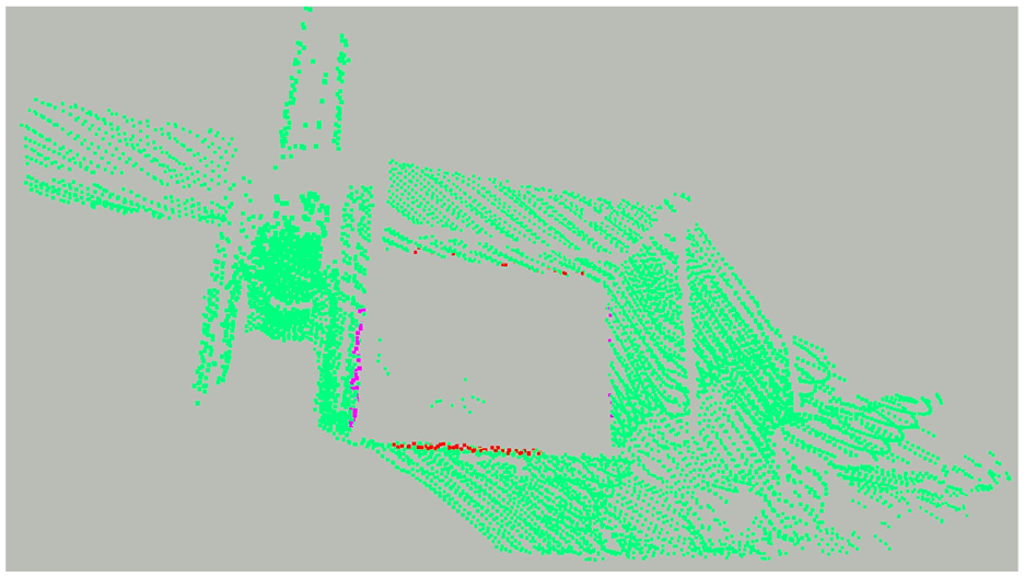
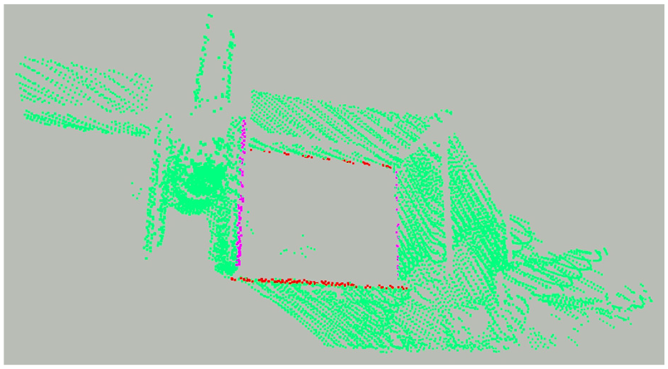
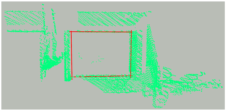
Point cloud of four edges of operation target.
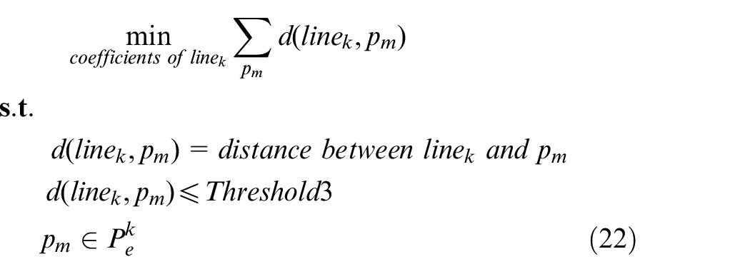
With the Sample Consensus Function of PCL Library, we calculate parameters of corresponding four straight line as the edges of hatch based on the identified four edges of the point cloud:
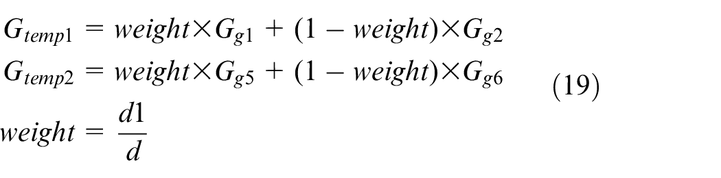
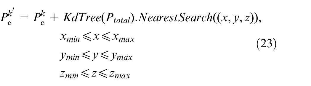
For real-time identification of operation targets, our algorithm only process point cloud of one frame once a time, and thus the points of hatchs edge detected in real time are not dense enough for accurate fitting of edge lines. To solve this problem, we use the 3D point cloud of the whole hull blocks built in former section as reference to complement the four edges point clouds and redo the straight line fitting in order to refine our estimation. To be specific, we build a KdTree with the point cloud of whole hull blocks as input, and search the KdTree for points neighbored to the four fitted straight lines and then add those neighbored points to the point clouds of four edges respectively:
Complete point cloud of four edges of operation target.
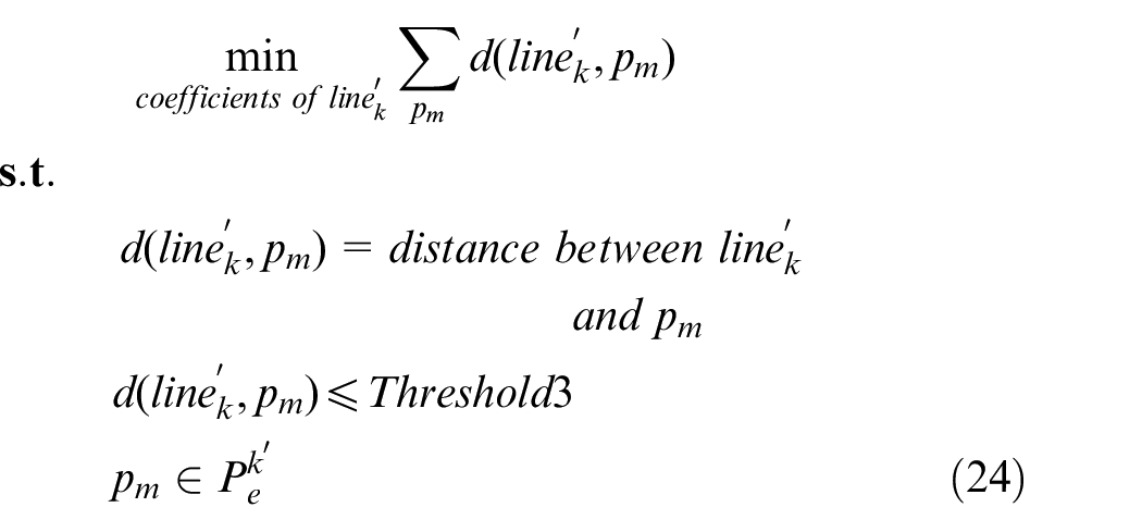
We redo the fit based on complemented point clouds
Refined edge lines.
Experiment
Experiment for our hull reconstruction algorithm and target identification algorithm is implemented on the ship loader at Tian Jian’s Shen Huang Coal Terminal. The lidar is mounted on the load as shown in Figure 9. The speed of moving scan system is
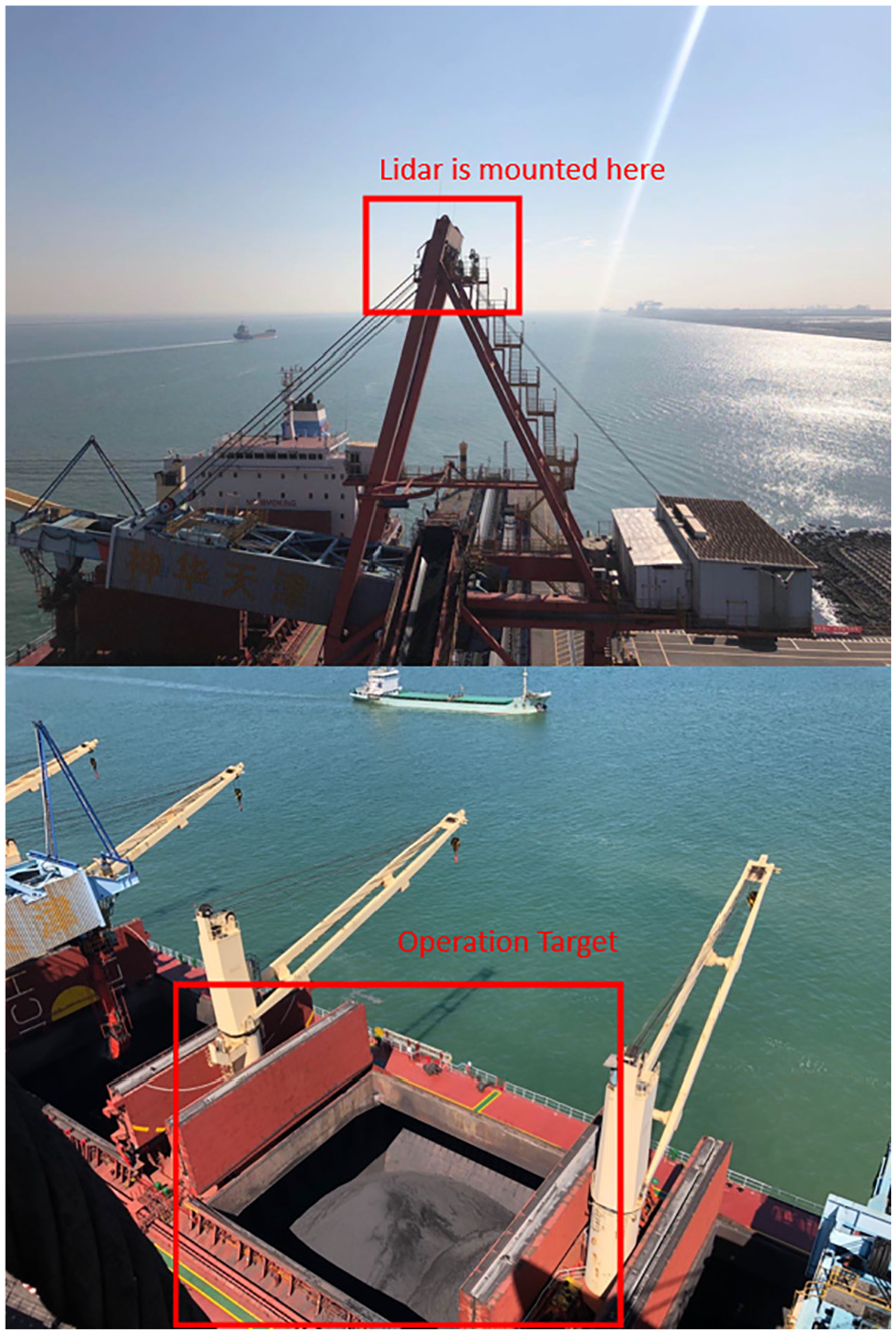
Experiment environment of the coal terminal.
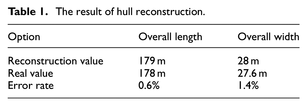
The 3D structure of the whole hull blocks is shown in Figure 3, and the result of hull reconstruction’s experiment is shown in Table 1. And the result of experiment on identification algorithm of operation target is shown in Table 2.
The result of hull reconstruction.
The result of target identification.
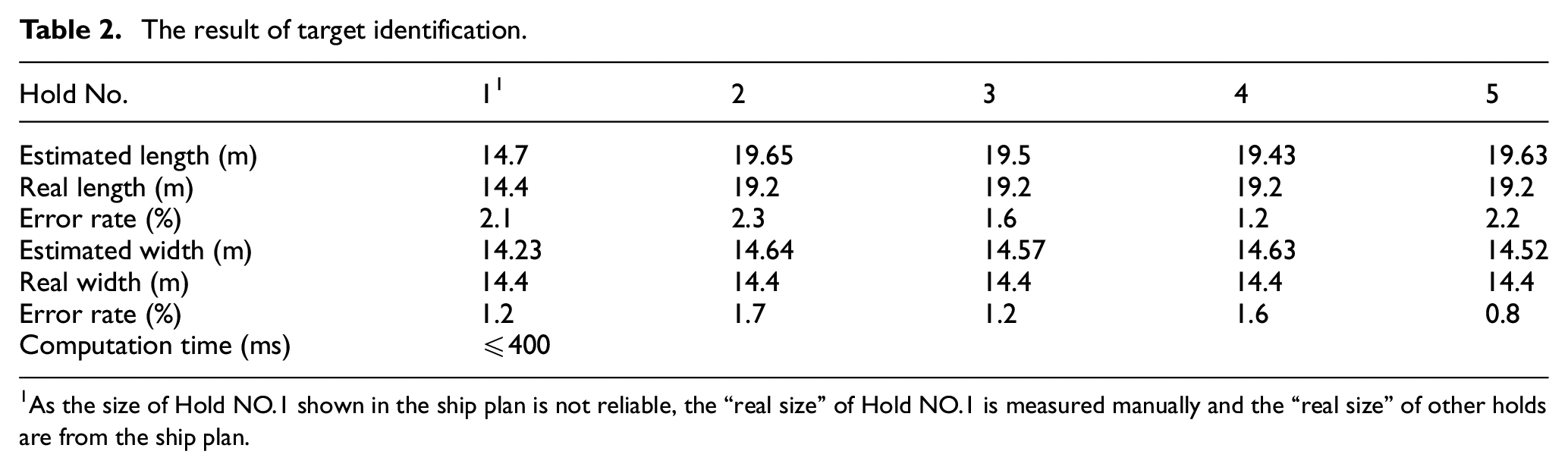
As the size of Hold NO.1 shown in the ship plan is not reliable, the “real size” of Hold NO.1 is measured manually and the “real size” of other holds are from the ship plan.
As shown in the Tables 1 and 2, the computation time of target identification is less than
The error in reconstruction of hull blocks is comparatively low (1.4% in width and 0.6% in length). The maximum error in target identification is 1.7% in width and 2.3% in length. In the result of target identification, the error in length estimation is generally larger than that in width estimation. The main reason of that is the estimated edge of width in the left (the left edge in purple shown in Figure 7) is deviated from the real edge not because of flaws in algorithm but because the lidar does not face straightly to the deck plane due to the operation environment, as shown in Figure 1 and thus the features of the left edge is not complete even in the rebuilt model of the whole blocks. To solve this problem, in the future, we will use multiple lidars at different angles facing toward the deck plane of cargo ships and merge point clouds collected by those lidars for identification, and then the accuracy of our target identification algorithm can be further improved.
Conclusion and future work
This paper presents a algorithm of reconstructing hull blocks of cargo ships based on a moving scan measurement system and a algorithm of identifying operation targets in real time with high accuracy. Our system and algorithm are simple and reliable. Firstly, LMS moves and scans the whole cargo ship at a uniform speed and then rebuild the 3D structure of hull blocks. Then, the LMS moves to operation zone of the ship, face to the operation targets and scan the zone constantly. Our identification algorithm processes the real-time point cloud streams for estimation the size and dynamic posture of operation target at a refreshing frequency of more than 2.5 frame per second, which makes it possible to guide the automatic ship loading in real time. The experiment results show that our system and algorithm works effectively and efficiently.
In order to further improve our system and algorithm and to apply them in real operation scenes in bulk terminals, in the future, we will do further research as follows:
In order to achieve higher accuracy of reconstruction of hull blocks and identification of operation targets, we plan to apply multiple lidars in measurement system with different directions toward the deck plane and to explore new algorithms of reconstruction and identification based on merged point clouds from multiple lidars.
As the loader switches between operation targets, obstacles like cranes and hatch lids on the deck may get in the way of the loader and result in collision. Thus, in order to facilitate the movement of the loader and avoid collision, the obstacles on the deck need to be mapped and the safe path free of obstacles for the loader can be planned.
The shape of bulk materials in hatches can be modeled to guide the loading system for the even distribution of materials and improving the utilization of space in the hatch.
Footnotes
Declaration of conflicting interests
The author(s) declared no potential conflicts of interest with respect to the research, authorship, and/or publication of this article.
Funding
The author(s) disclosed receipt of the following financial support for the research, authorship, and/or publication of this article: This work was supported by National Key R&D Program of China (No.2018YFB1308404).