
Abstract
The load side and the motor connected by flexible joints in the manipulators’ joint servo system. During the motion of manipulators driven by tendon-sheath, the status change of the end-effector will result in the change of the load side rotational inertia. The perturbation of the inertia of the load side will result in the modeling mismatch of the servo system. So the modeling uncertainty and the system robustness will decrease. An adaptive sliding mode robust control based on HJI (Hamilton-Jacobi-Issacs) theory is proposed in this paper to improve the robustness of the system. Firstly, according to D-H coordinate method, kinematics and dynamics models of the manipulator are established. Then, the basic strategy of adaptive sliding mode robust control is proposed. The variation of control parameters of a single joint of the manipulator is adjusted to reduce the control cost. Next, the sliding mode control law was established through the design of the Lyapunov function based on the HJI theory. The manipulator dynamics model was taken as the research object. The simulation analysis was conducted in uncertain parameters. Finally, a series of manipulator prototype experiments were carried out to proof our control theory. The experiment results show that our method can better solve the model uncertainty caused by the servo system. The adaptive sliding mode robust control strategy based on HJI theory has lower dependence on accurately modeling and stronger robustness.
Keywords
Introduction
With the development of intelligent robots, 1 as an important part of robots, the design and control of manipulators is the key to research. 2 In consideration of economic costs and control factors, two schemes are adopted in the design of light manipulators. One is driven by traditional motor and reducer, such as ASIMO 3 and Sophia, 4 which has a small load and is easy to control. The other scheme is driven by PMSM (permanent magnet synchronous motor) and harmonic reducers, such as ABB-Yumi, 5 LR-Justin, 6 Rethink-Baxter, 7 Saywer, 8 and Kinova-Jaco. 9 The manipulator not only has a large structural but also has a high cost. For the above reasons, tendon-sheath has been applied in manipulators, such as WAM 10 and LIMS2. 11 But these manipulators mainly realize long-distance transmission through pulleys. The excessively complex structure makes the manufacturing and control cost of the system high. In order to reduce the cost, this paper proposes a scheme of a rear-mounted motor by tendon-sheath transmission. We designed a 6-DOF manipulator with reference to the shoulder, elbow, and wrist joints of the human arm.
During the movement of the manipulator driven by tendon-sheath, the poses change of the end-effector will lead to the change of the load side rotational inertia. 12 The perturbation of the moment of inertia of the load side will cause the modeling mismatch of the system, generate modeling uncertainty, and reduce the robustness of the system. How to calculate the dynamic torque in real-time and compensate it in the process of motion has always been the key to manipulator control. 13 On the other hand, considering the cost factor, the load side of manipulator the will change with the rotation of the joint during the driving process. The change of the control drive signal will not be too large, which requires the restriction of the control signal.
For the manipulator system, considering the model uncertainty and the system robustness under external disturbances is an important prerequisite to improve the fault tolerance of the control system. Sliding mode control (SMC) is a robust control technology that can effectively deal with system uncertainties and has been studied in robot modeling, 14 robot motion control, 15 and robot system stability analysis.16–18 Jafarov et al. 19 took the lead in putting forward PID sliding mode controller with PID sliding mode surface based on sliding mode control, and applied it to a double-chain directly driven robot arm, and achieved satisfactory performance. Efe 20 proposed a parametric adaptive sliding mode control method, simulated the dynamic model of the 2-DOF directly driven robot arm, and obtained good robustness performance. Jin et al. 21 proposed a model-free robust adaptive controller for the interference torque generated by the flexible joint of the robotic arm, designed a sliding mode controller using the gain adaptive law, and carried out experimental verification on the flexible joint robot. All the above researches are based on sliding mode control, and the uncertainty of torque parameters of the manipulator is studied. Some researches on robustness are considered, but the anti-jamming capability of the system is not considered from the perspective of the numerical algorithm.
In this paper, some researches on sliding mode control based on adaptive law are done according to the HJI theory.22–24 First, the dynamics model of the 6-DOF manipulator is obtained by establishing the dynamics and kinematics model of the manipulator. Then, the basic strategy of adaptive sliding mode robust control is proposed. The control parameters are designed by mapping an adaptive algorithm. 25 The asymptotic stability of the system under the Lyapunov theory is guaranteed. Based on the HJI theory, a kind of anti-interference performance index was defined. The Lyapunov function was designed under the condition of adaptive law, and a sliding mode controller satisfying the conditions was established. Finally, the proposed theory is verified by system simulation and prototype experiment, and good response characteristics of the manipulator are obtained, which proves that the proposed theory has good robustness.
The structure of the paper is as follows: In chapter 2, kinematics and dynamics analysis of the manipulator are modeled. The third chapter introduces and designs the control system of the manipulator. The fourth chapter carries on the simulation verification analysis of the proposed control strategy. The fifth chapter introduces the experimental prototype and carries on the experimental verification. Chapter 6 introduces the conclusion.
Dynamics and kinematic analysis of manipulator
Kinematic modeling of the manipulator
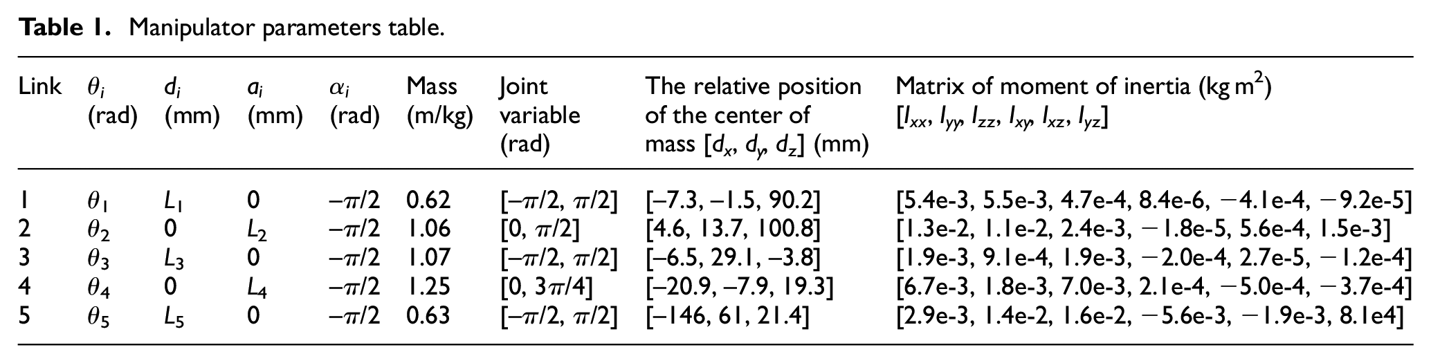
The 6-DOF manipulator designed in this paper is composed of six revolved joints, and its structure is shown in Figure 1. Among them, joints 1, 2, and 3 achieve similar movements of a human arm and shoulder joints. Joints 5 and 6 achieve carpal movement. Joint 4 provides elbow like motion. Joint 1 is driven directly by a motor through a reducer and is located at the bottom of the mechanical arm, while the rest of the joints are driven by tendon-sheath. The D-H method was improved, and the connecting rod coordinate system of the mechanical arm was established, as shown in Figure 1. The relevant parameters of the manipulator are shown in Table 1. It is defined that the Angle is positive when rotating clockwise and negative when rotating counterclockwise.
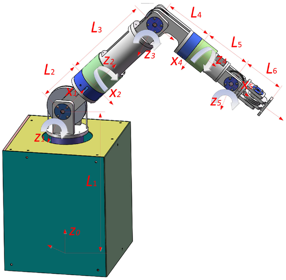
The structure of the manipulator.
Manipulator parameters table.
Where
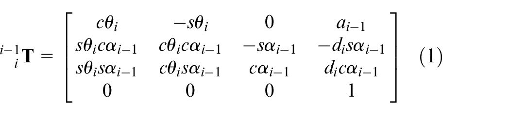
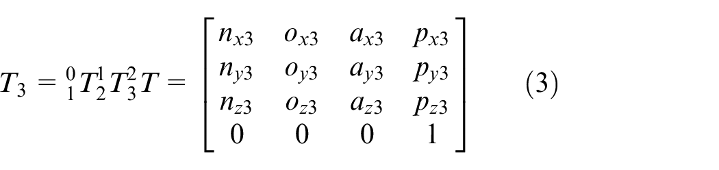
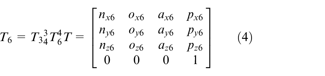
The kinematics equations of the shoulder joint and the end-effector of the manipulator can be obtained from the transformation formula of the links and the transformation transfer formula. The transformation formula of the links is shown in equation (1). The transformation transfer formula is shown in equation (2). The expression of the poses of the shoulder joint is shown in equation (3), and the expression of the poses the end-effector of the manipulator is shown in equation (4).

The workspace is an important performance index to evaluate the working ability of the manipulator. It is a description of the end effector working area. The workspace can be described by the set of position points reached by the manipulator. The end position of the manipulator is the equation about the angle of rotation. The expression of the working space of the manipulator is as shown in equation (5).

In equation (5),

Manipulator workspace: (a) 3D workspace of the manipulator; (b)Schematic diagram of the links of the manipulator.
Dynamics model of the manipulator
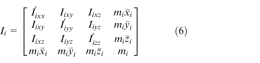
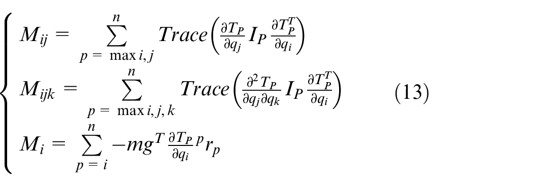
The pseudo-inertia matrix of the manipulator is the inertia of each rotation direction of the links which can be expressed as follows:
The kinetic energy of link
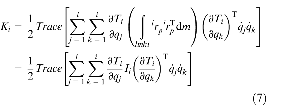
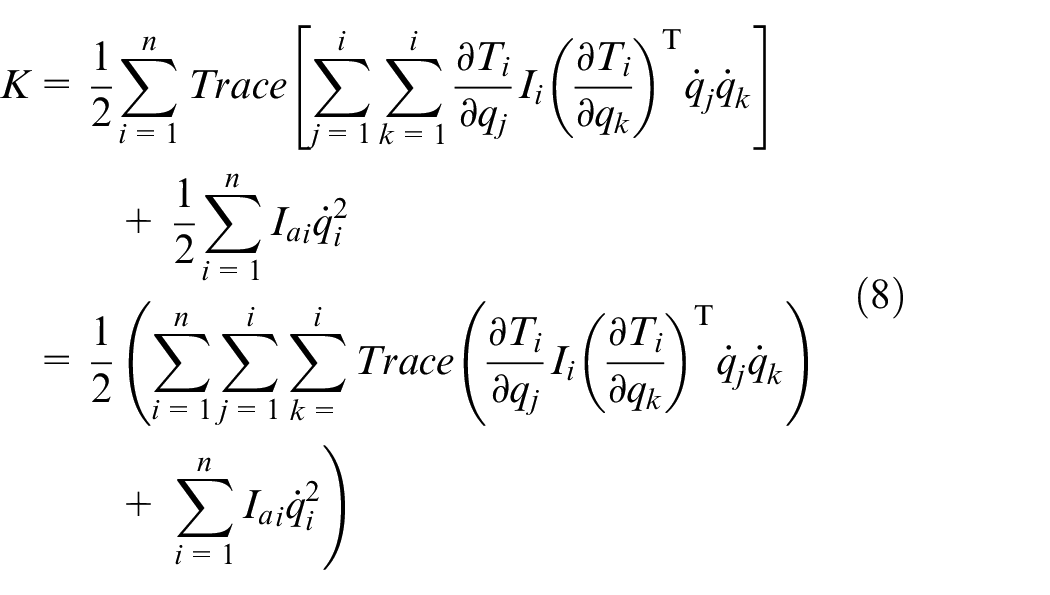
Thus, the total kinetic energy of the manipulator can be expressed as:
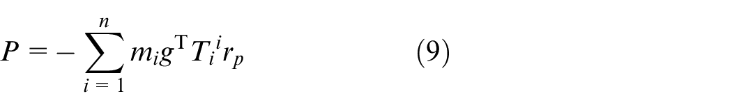
The total potential energy of the manipulator can be expressed as:
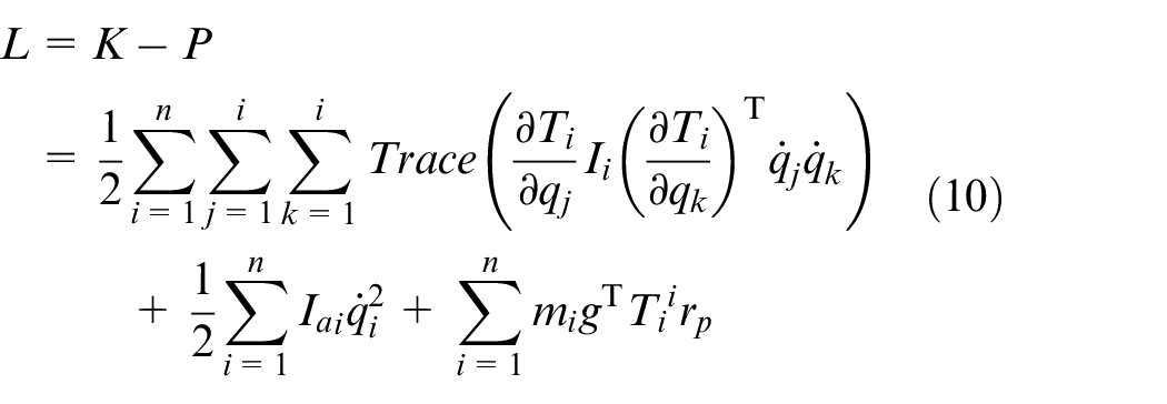
After the kinetic energy and potential energy expressions of the manipulator are obtained, the Lagrange function can be obtained, whose expression is as follows:
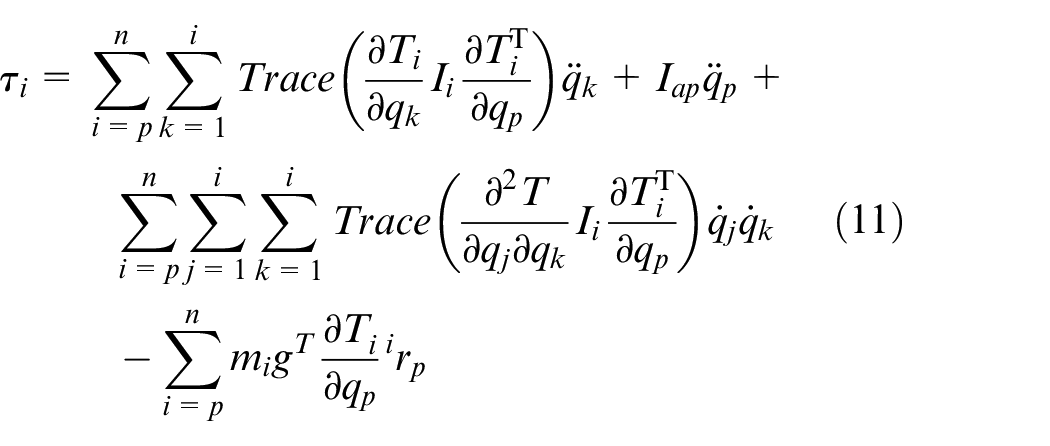
According to the Lagrange dynamics theorem, the dynamic equation of the manipulator can be obtained as follows:
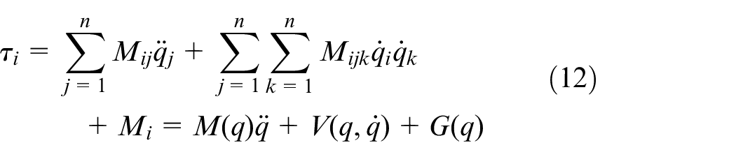
Equation (11) can be written as equation (12).
where
Dynamic modeling of flexible single joint of the manipulator
The manipulator can realize the separation of the motor and the joint through the double tendon-sheath transmission, further reducing the body mass of the manipulator. The double tendon-sheath transmission consists of two sleeves and two flexible cables, which can transmit force and displacement. The transmission principle is shown in Figure 3. The motor is connected to the reducer. The driving wheel is installed on the output shaft of the reducer, and the driven wheel is placed in the joint. The rotation of the motor is transmitted to the driving wheel through the reducer, and then the driving wheel drives the driven wheel on the joint to rotate through tendon-sheath transmission and then drives the load side to move.
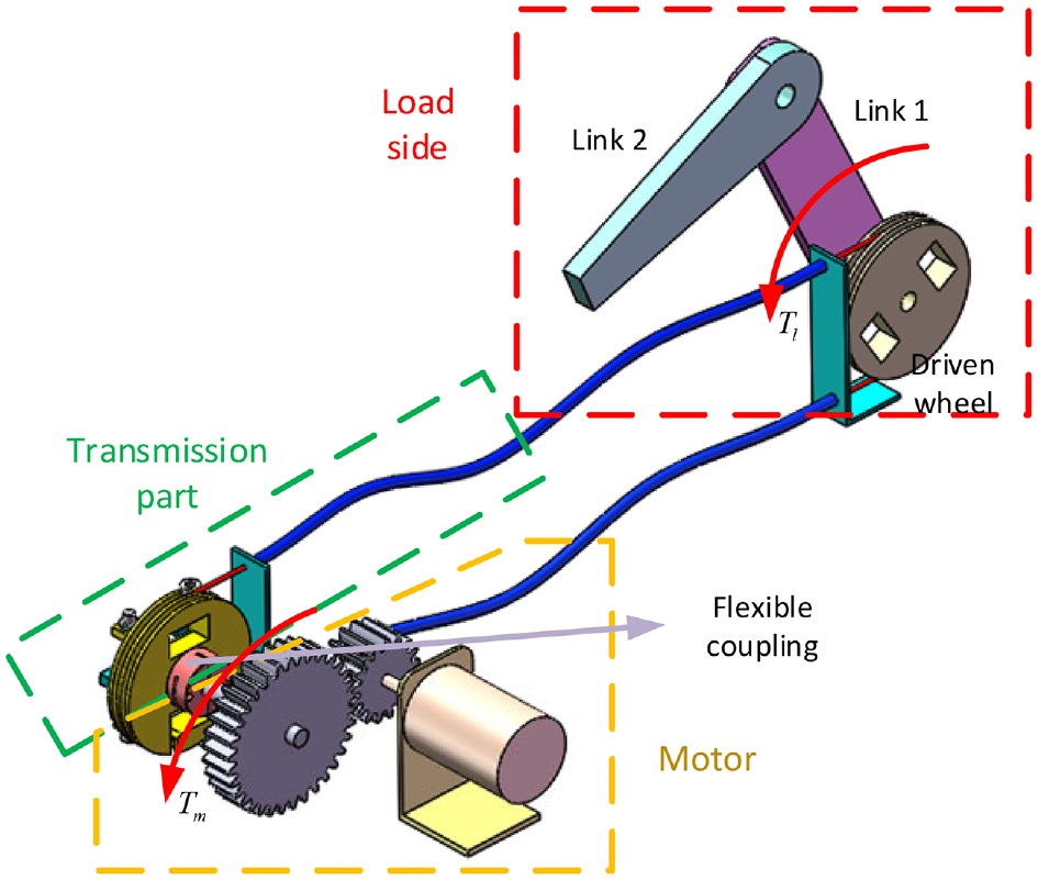
Schematic diagram of double tendon-sheath transmission.
The typical joint structure of the manipulator is shown in Figure 4. Figure 4(a) is a structural diagram of the second joint. The driven wheel and the connecting piece are fixedly connected to the base through a bearing. There are two flexible cables around the driven wheel in different directions. One side of the flexible cable is fixed on the driven wheel, and the other side passes through the pulley to change back into the casing. Figure 4(b) is the three structure diagram of the joint. The driven wheel is fixedly connected to the main shaft and installed in the bearing sleeve through the bearing. Two flexible cords wound in different directions on the driven wheel. One side of the flexible cable is fixed on the driven wheel, and the other side passes through the pulley to change back into the casing.
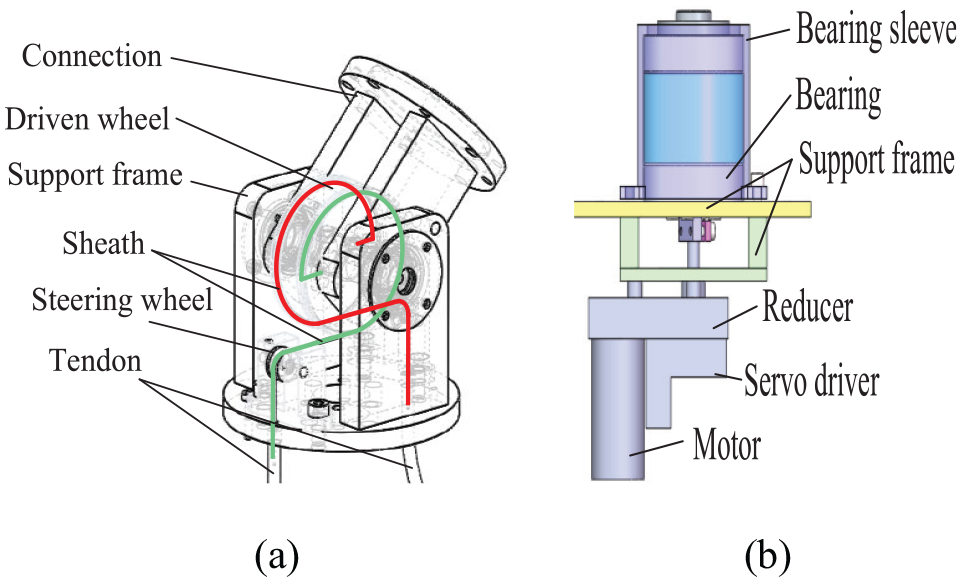
Schematic diagram of a typical joint: (a) the structure of Joint 2 and (b) the structure of Joint 3.
In the joint servo drive system of the manipulator the motor and the load are connected through a reducer, an elastic coupling, and a tendon-sheath. Elastic coupling and tendon-sheath have a certain flexibility, so the transmission part can be equivalent to a torsion spring-damping model. One side of the torsion spring is connected to the motor, and the other side is connected to the load. The simplified flexible joint servo drive system is shown in Figure 5:
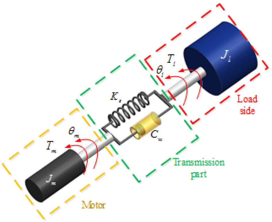
Schematic diagram of flexible joint servo drive.
The moment of inertia at the motor side consists of two parts. One part is the moment of inertia of the motor itself, and the other part is the moment of inertia of the load. This part of the moment of inertia is related to the inertia matrix of the manipulator and the reduction ratio. Therefore, the motor load of the single joint of the robotic arm is as shown in equation (14).
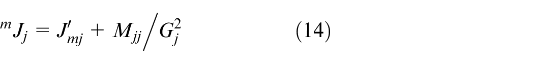
where
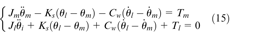
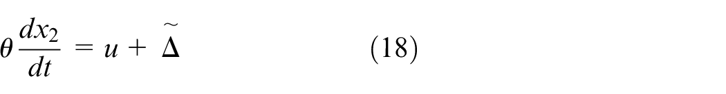
The dynamic equation of the flexible joint servo drive system is as shown in equation (15).
Adaptive sliding mode control
Adaptive control can automatically modify the system characteristics to adapt to uncertainties and disturbance dynamic characteristics changes. Robust control can maintain the original performance of the system under a certain perturbation of the control system parameters.
Manipulator flexible joint control strategy
Problem description
The control core of the manipulator driven by the tendon-sheath is the servo system control of the flexible joint. The problem can be simplified and described as follows:
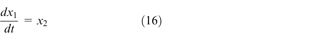
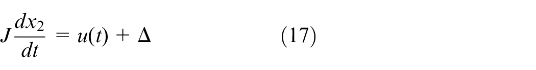
Among them,
Take
Assumption 1: The upper and lower bounds of the uncertain parameter

Assumption 2: The uncertain term

Controller design
Define the sliding mode function as:

Among them,
So there is as shown in equation (22).

Take
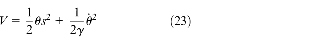
Among them,
Then,
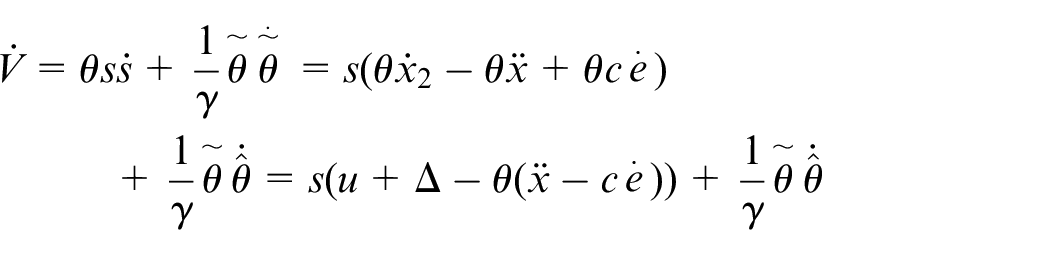
(24)
Then, the control law is designed as:

Among them,
Lyapunov stability analysis
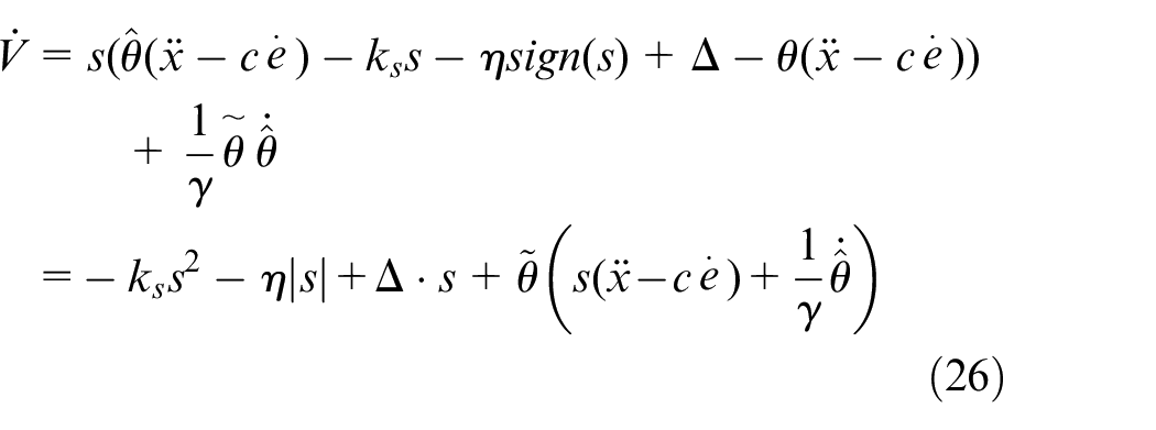
Substituting the control law (25) into the equation (24), we can get equation (26).
Take the adaptive law as:
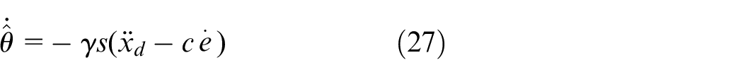
We can get the equation (28).

Because only if
Theorem 1:
Suppose
Suppose:

And suppose that the trivial solution
According to Theorem 1, the closed-loop system is asymptotically stable. That is when
Because
In order to prevent
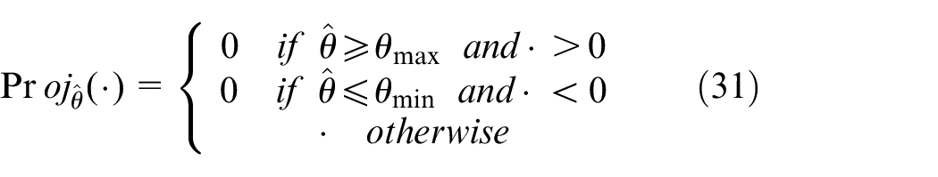
When
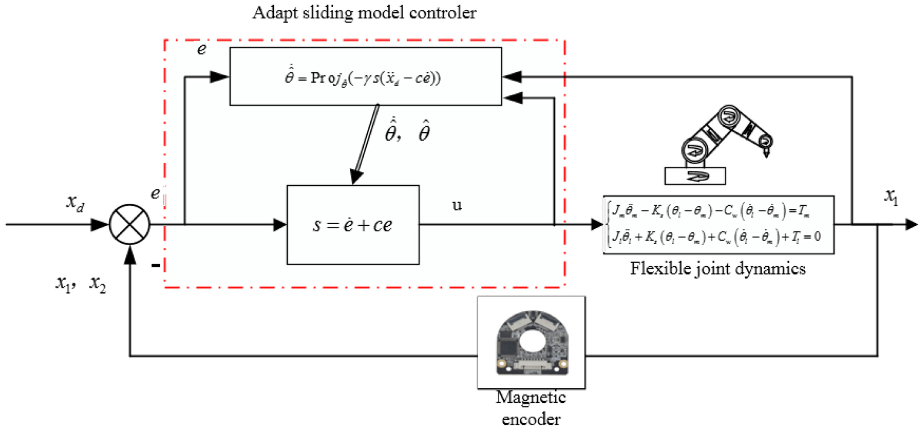
Adaptive sliding mode robust control strategy.
Control strategy of the entirety manipulator
Problem description
Consider the following system as shown in equation (32).
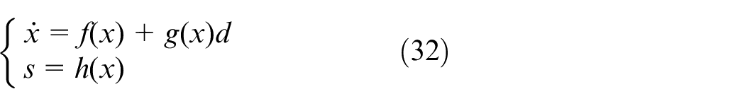
Where,
The sliding mode function is defined as the evaluation signal, that is
In order to represent the anti-interference capability of the system, the following performance indexes are defined as shown in equation (33).
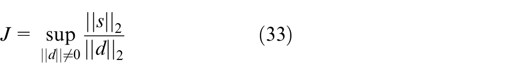
where
Obviously, the value of
According to theorem 2 in literature, 14 the HJI (Hamilton-Jacobi Inequality) theory is described as follows:
For any given positive number
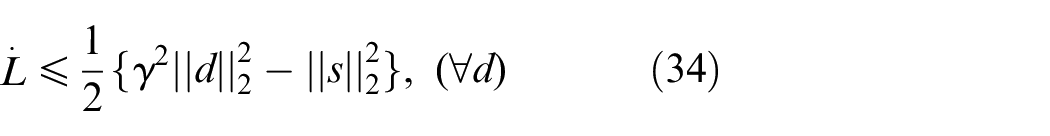
The
Controller design
Described by the question, we can design the sliding mode control law and Lyapunov function to make its meet equation (34). So, the conditions of the
Considering the dynamic equation of flexible multi-joint mechanical arm, the equation (35) can be obtained.

Among them, the
The ideal position instruction is

where,
By substituting the control law (36) into the dynamic equation (35), the equation (37) can be obtained.

Taking

The sliding mode function s is defined as the evaluation signal. So the equation (39) can be obtained.

Among them,
So the equation (40) can be obtained.
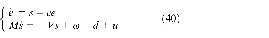
Equation (40) is written as HJI conditional form, as shown in equation (41).
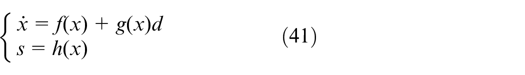
Among them,
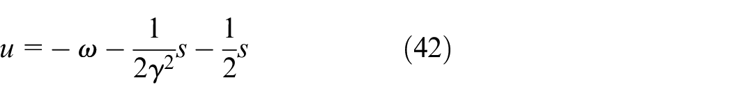
So in order to satisfy the equation (38), control law can be designed as shown in equation (42).
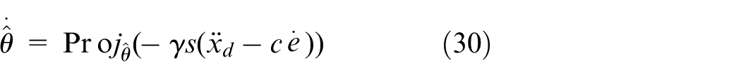
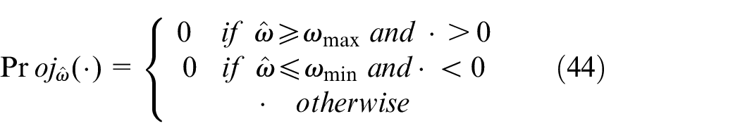
In order to ensure the effectiveness of the control signal, the adaptive mapping strategy is adopted to limit
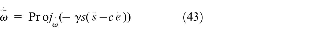
Among them, the equation (44) can be obtained.
Lyapunov stability analysis
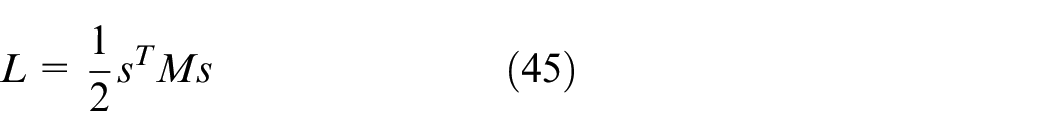
To prove the effectiveness of the control law design, the Lyapunov function is defined as shown in equation (45).
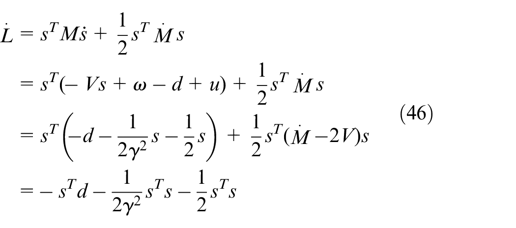
So the equation (46) can be obtained.
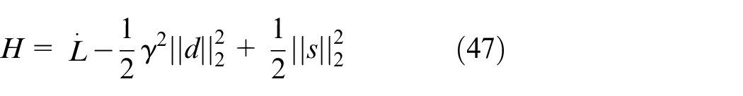
Definition:
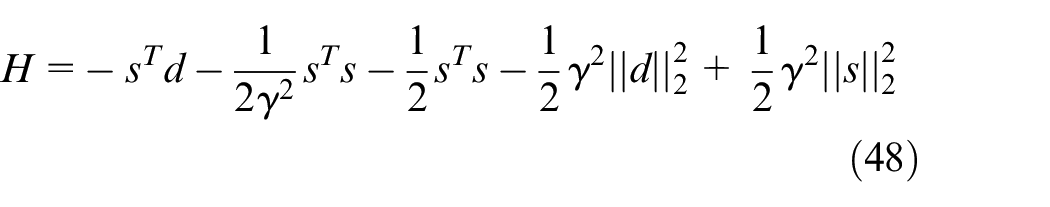
So the equation (48) can be obtained.
Because
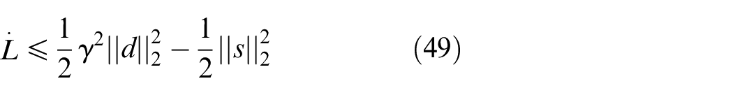
According to the theory of HJI available
Simulation analysis
Adaptive sliding mode control simulation
Take the flexible servo system described in question (1) (2) as the controlled object, and the simulation parameters are shown in the following table. Take system friction interference model as
The simulation parameters are shown in the following table:
If the traditional PD control is used for the robotic arm, take the control parameters
Angle tracking and error curve of joint 1 under control law PD.
Angle tracking and error curve of joint 2 under control law PD.
The simulation results show that the traditional PD control cannot guarantee precise control of the flexible lasso manipulator, and the error cannot be stabilized to a certain value range, and there are still fluctuations.
Introduce sliding mode control to the control of joints 1 and 2. If the adaptive law (14) is not added, according to the control law (10) simulation, we can get (Figures 9 and 10):
Angle tracking and angular velocity tracking of joint 1 based on control law (10).
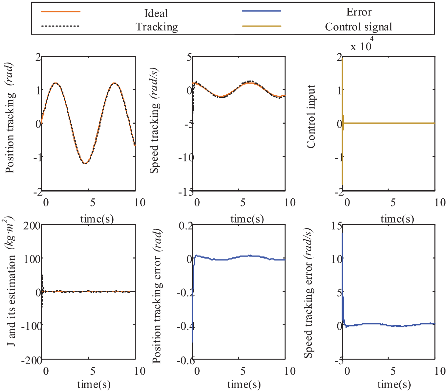
Angle tracking and angular velocity tracking of joint 2 based on control law (10).
The simulation results of joint 1 and 2 show that the angle tracking and angular velocity tracking during the movement can be better fitted, and the error curve can be stabilized in a short time; but we can see that at the beginning of the control, the control signal fluctuates very sharply. For actual control, this kind of control signal change is very unfavorable to the motor and the control cost is too high.
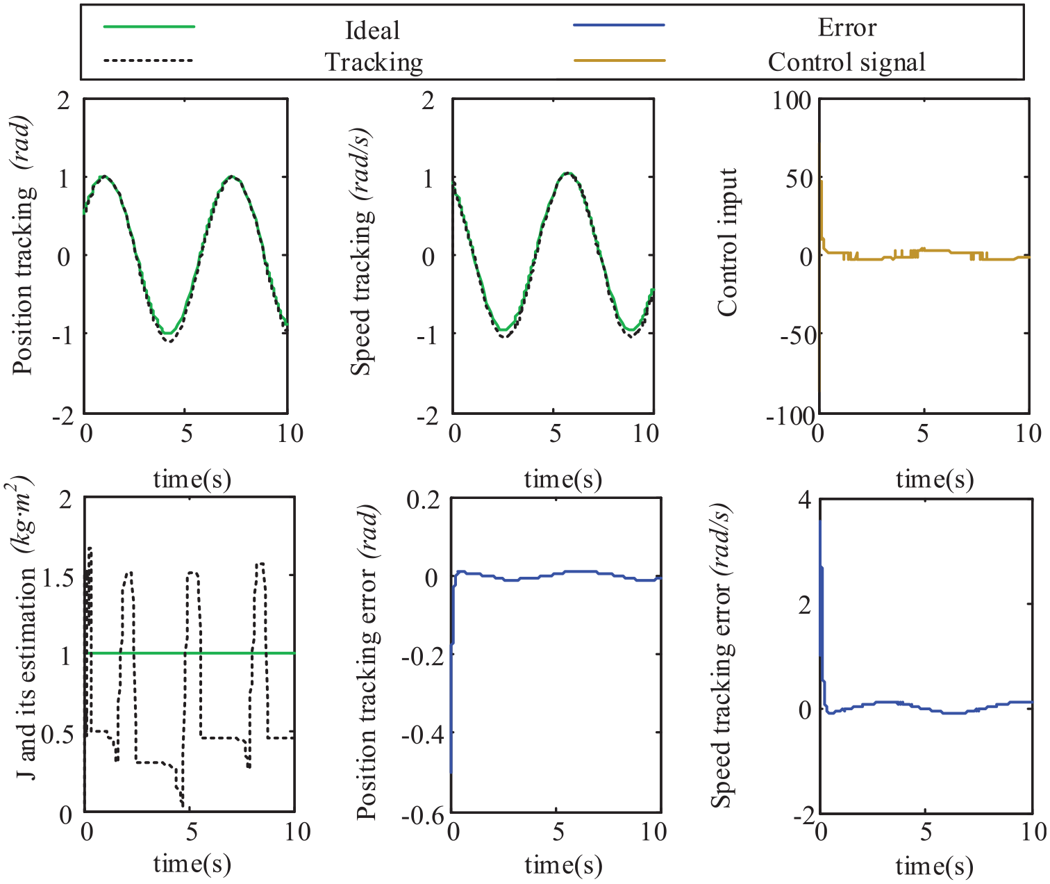
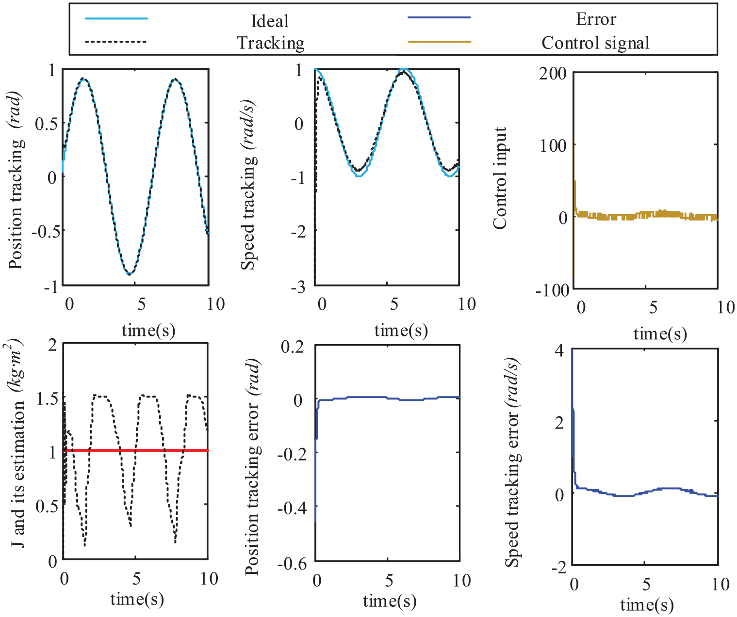
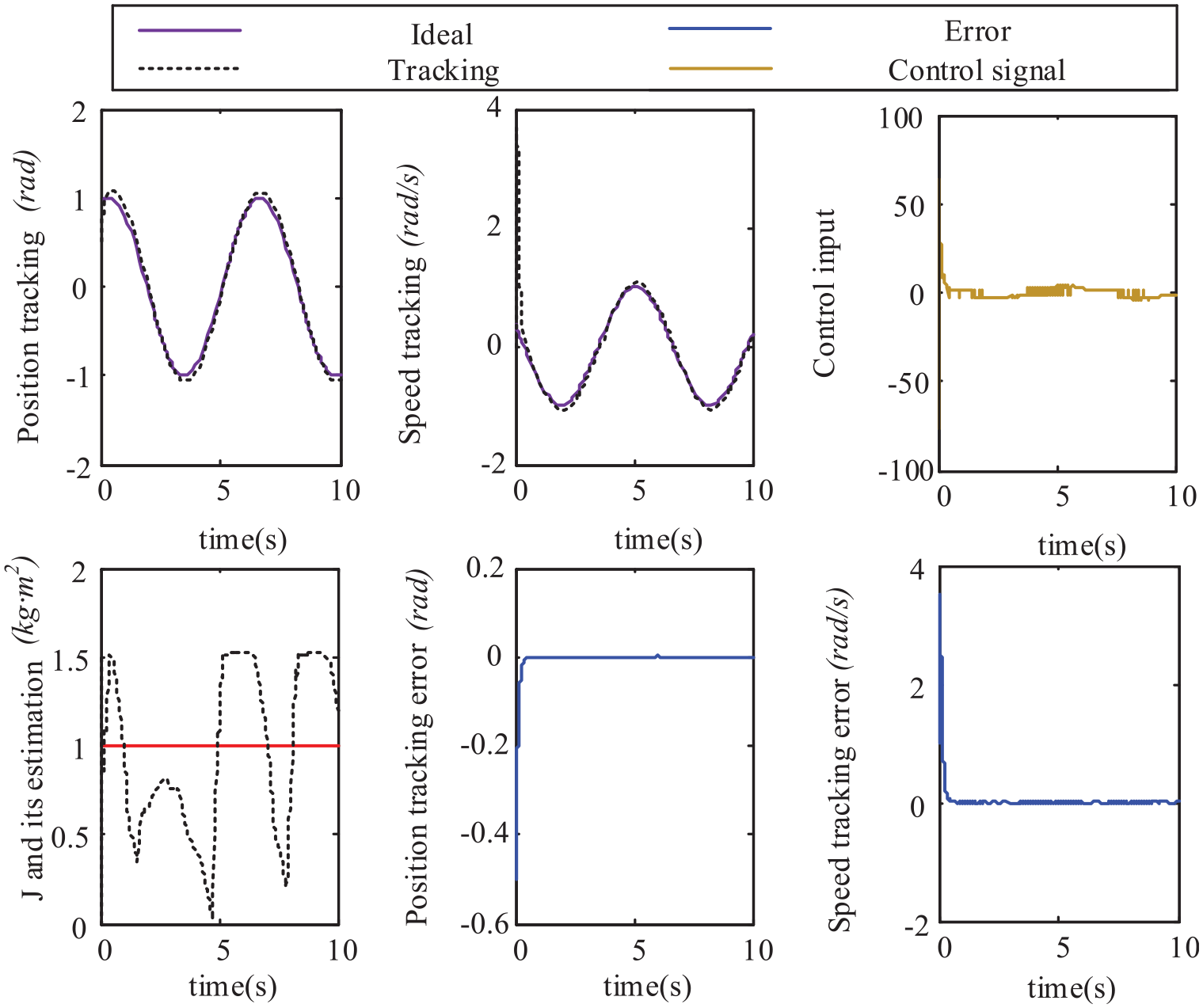
Introduce adaptive law (14) for simulation, and perform related simulation analysis on 1–6 joints (Figures 11 –16):
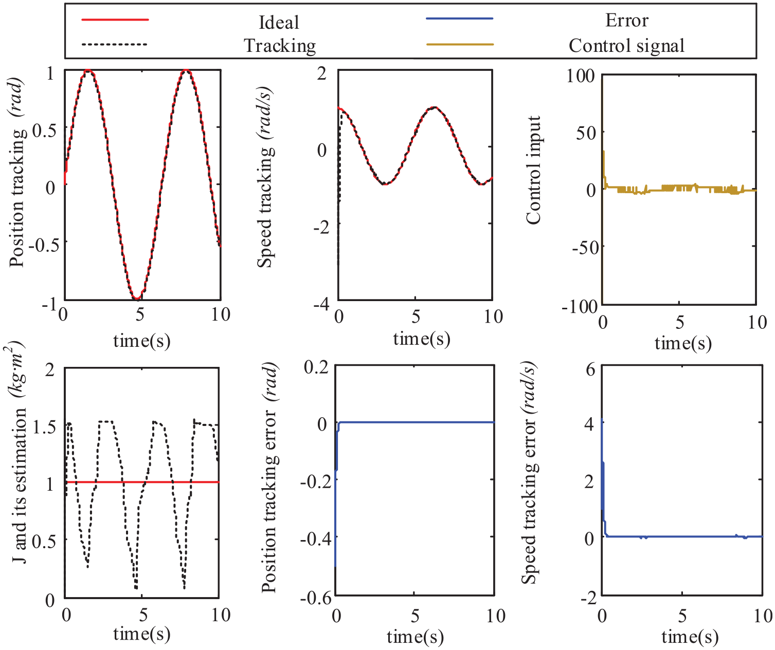
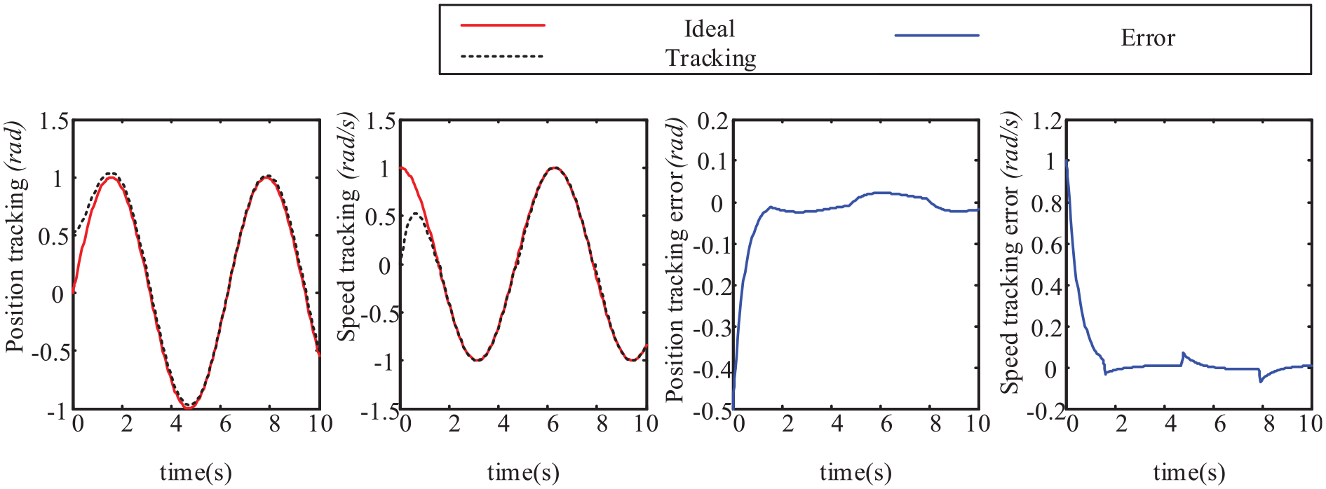
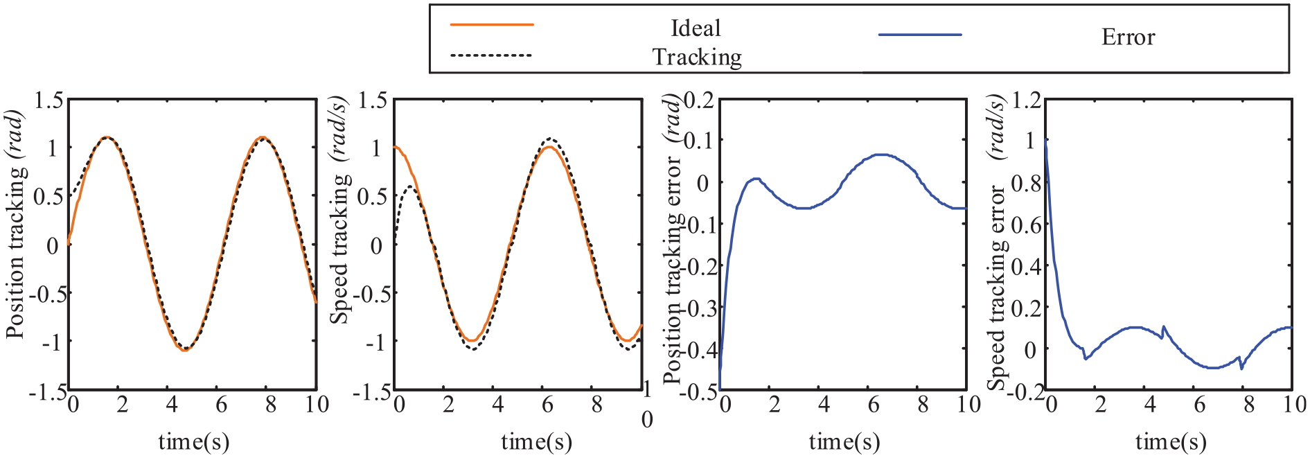
Angle tracking and angular velocity tracking of joint 1 based on adaptive law (14).
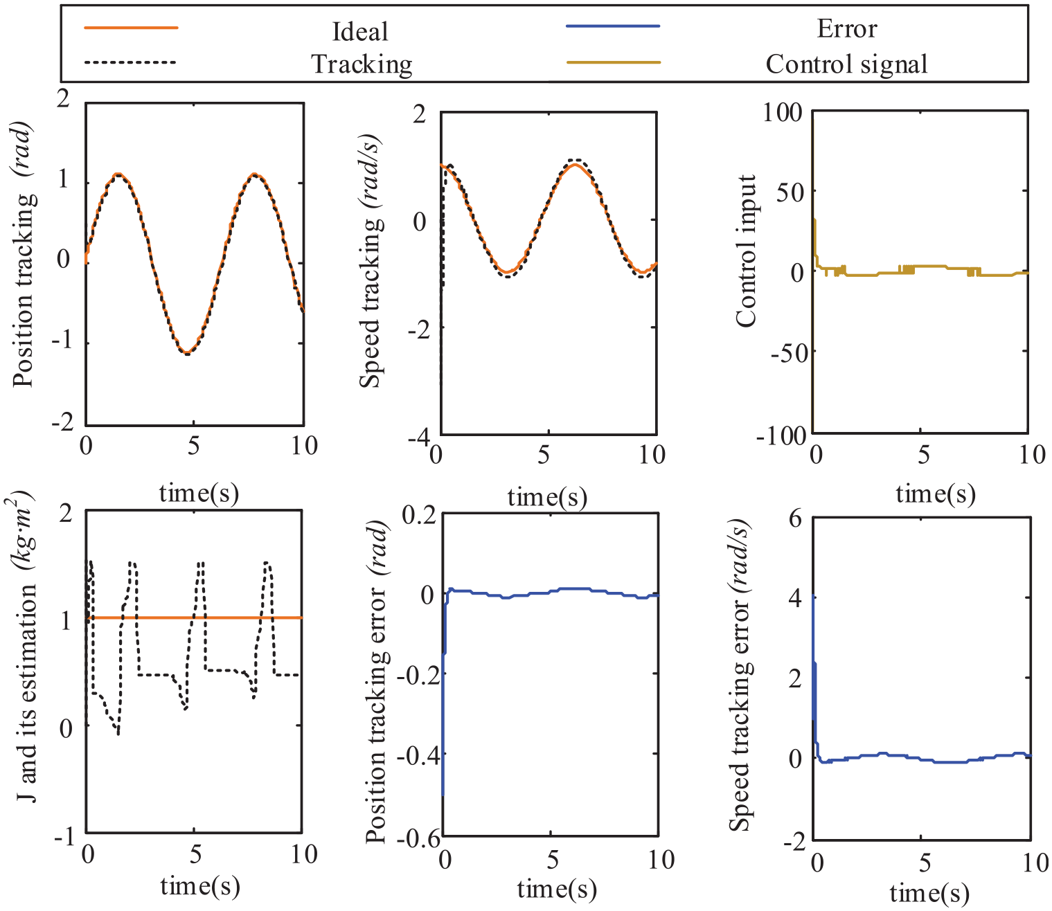
Angle tracking and angular velocity tracking of joint 2 based on adaptive law (14).
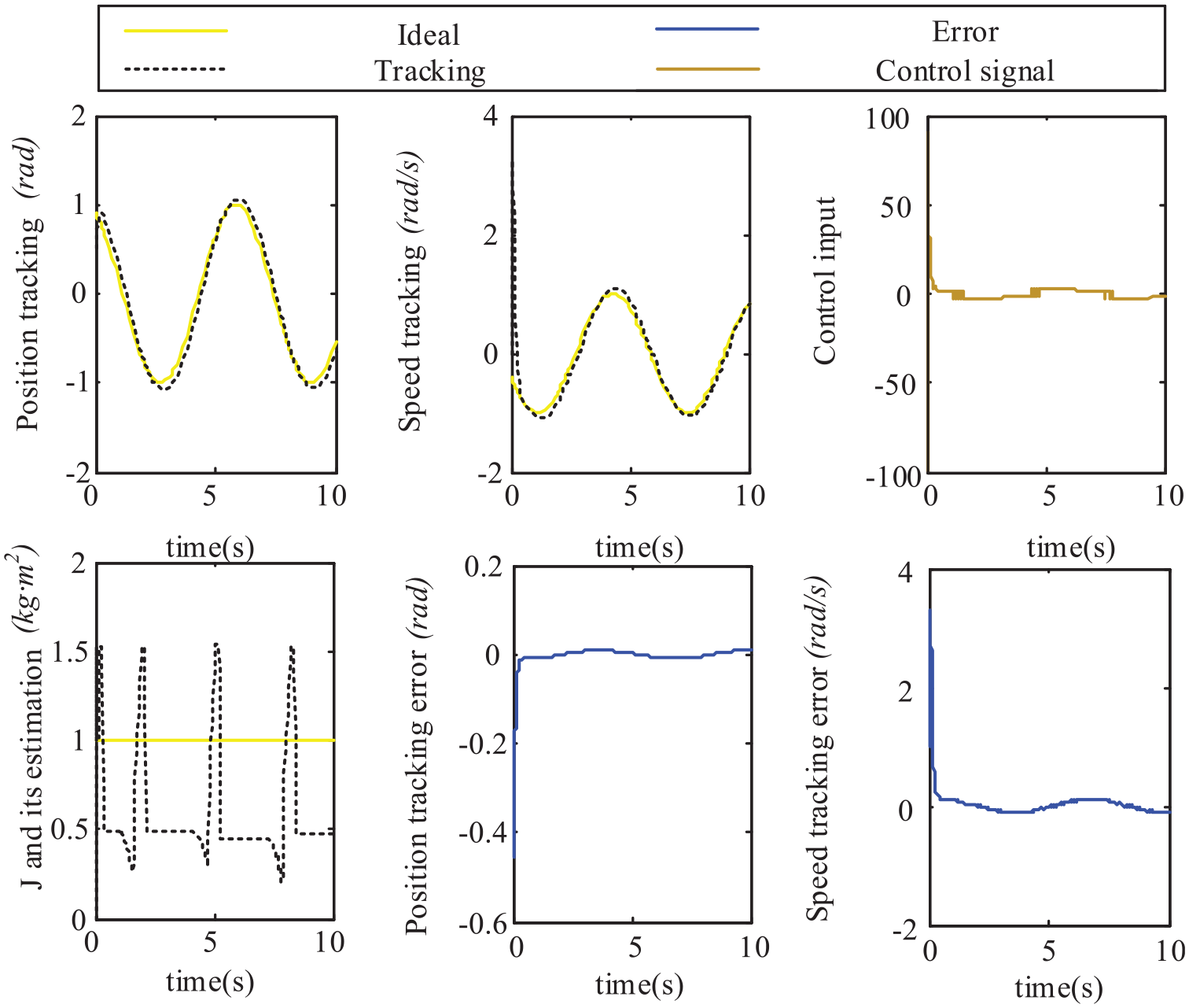
Angle tracking and angular velocity tracking of joint 3 based on adaptive law (14).
Angle tracking and angular velocity tracking of joint 4 based on adaptive law (14).
Angle tracking and angular velocity tracking of joint 5 based on adaptive law (14).
Angle tracking and angular velocity tracking of joint 6 based on adaptive law (14).
Through the tracking experiment simulation of joints 1–6, it can be seen that both angle tracking and angular velocity tracking can maintain good curve fitting; according to the control signal, it can also be seen that the system can be stabilized in a short time.
Adaptive sliding mode robust control simulation based on HJI theory
Take the dynamic equation of the robotic arm:

Among them,
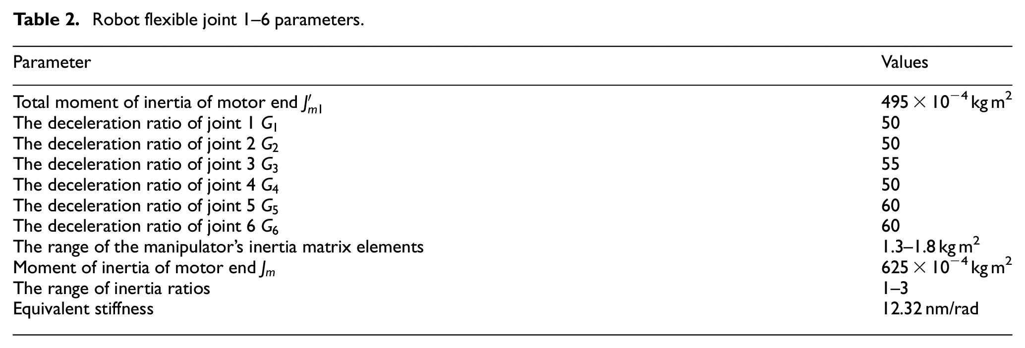
Take
Robot flexible joint 1–6 parameters.
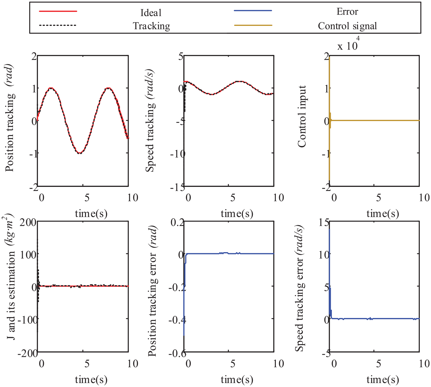
The joint angle and angular velocity tracking simulation is as follows (Figures 17 and 18):
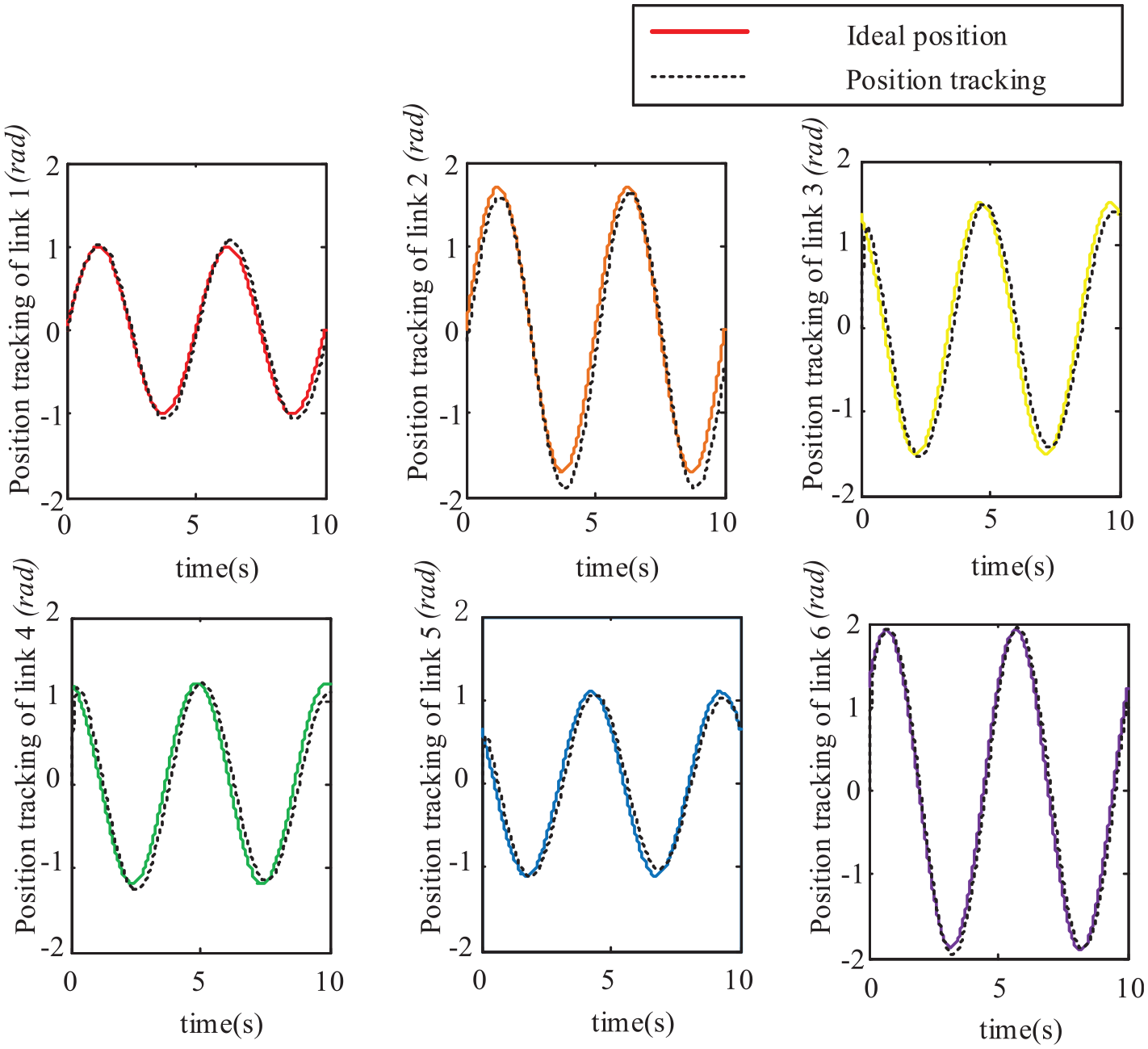
Angle tracking of joints 1–6.
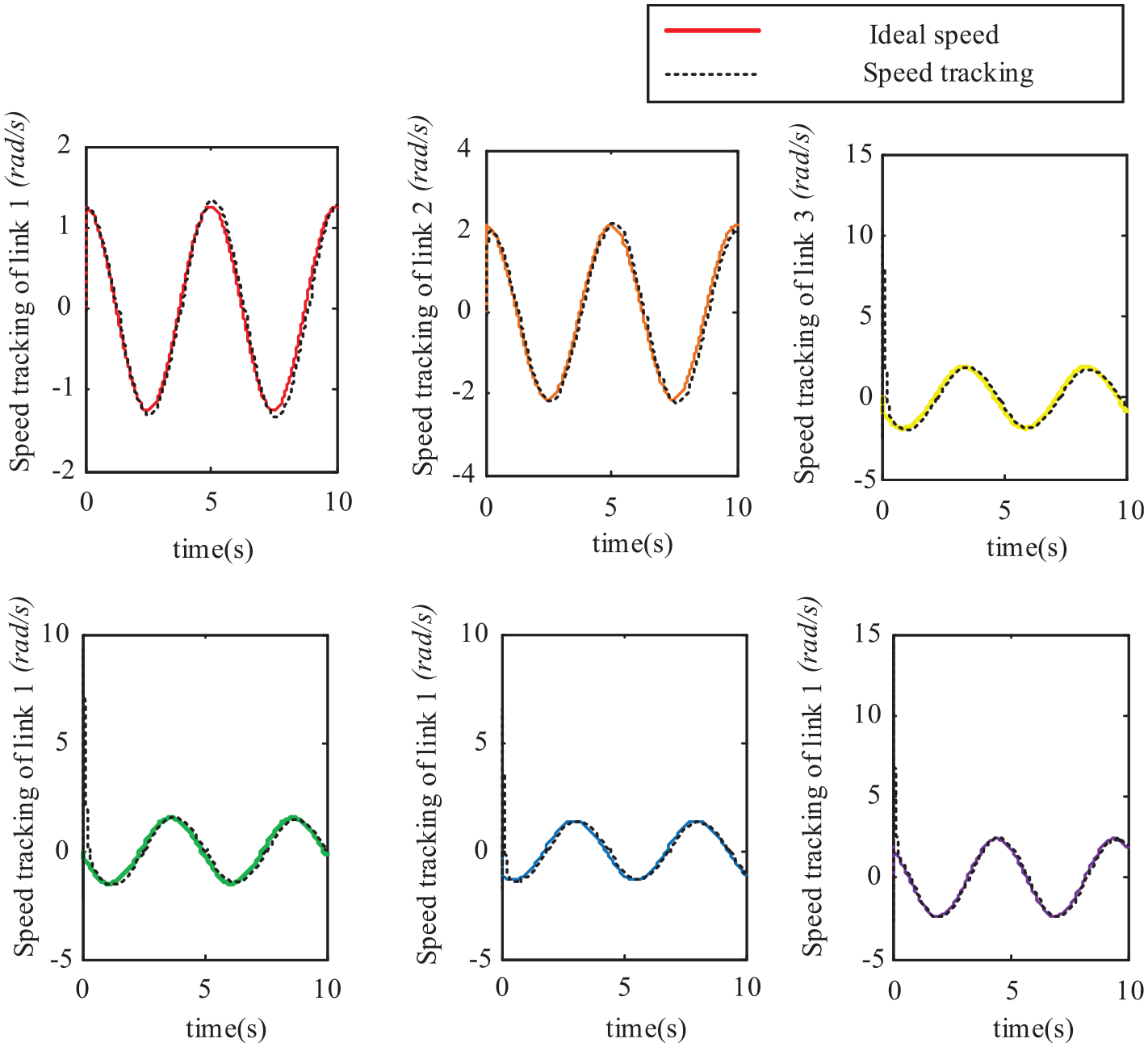
Angular velocity tracking of joints 1–6.
Different joints of the manipulator have different ranges of changes. After the Lyapunov function is designed through HJI theory, we can simulate and track the change signals of each joint more realistically. The initial phases of the six joints are different, but compared with the angular velocity tracking curve, it can be seen that they can all fit the input signal in a short time.
Prototype experiment
Prototype
The prototype test platform built in this paper is shown in Figure 19. The motor adopts the steering gear ASME-MRB with its own reducer (maximum output torque is 38 Nm), the flexible cable adopts the steel wire rope with a diameter of 1 mm, and the casing adopts the spiral sleeve with an external warp and an internal diameter of 2.2 mm wrapped by the rectangular spring wire. The control system of the manipulator adopts Ni-CRIO-9067 as the lower computer, and the hardware structure of the system is shown in Figure 19. The control program is written by Labview software on the upper computer, and then downloaded to the lower computer running the real-time system for execution through I/O interface. The feedback signal of joint angle is measured by the encoder and input into ni-9205 module, and the motion control signal is output to the motor driver by Ni-9264 module. The frequency of real-time feedback and data monitoring is set to 1 kHz.
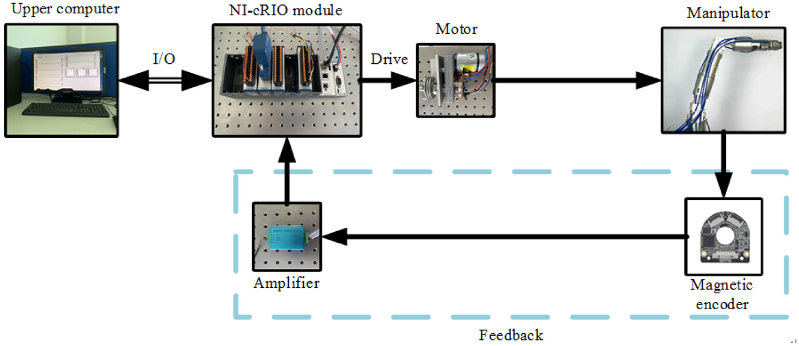
Experimental prototype control system.
Manipulator joint control experiment
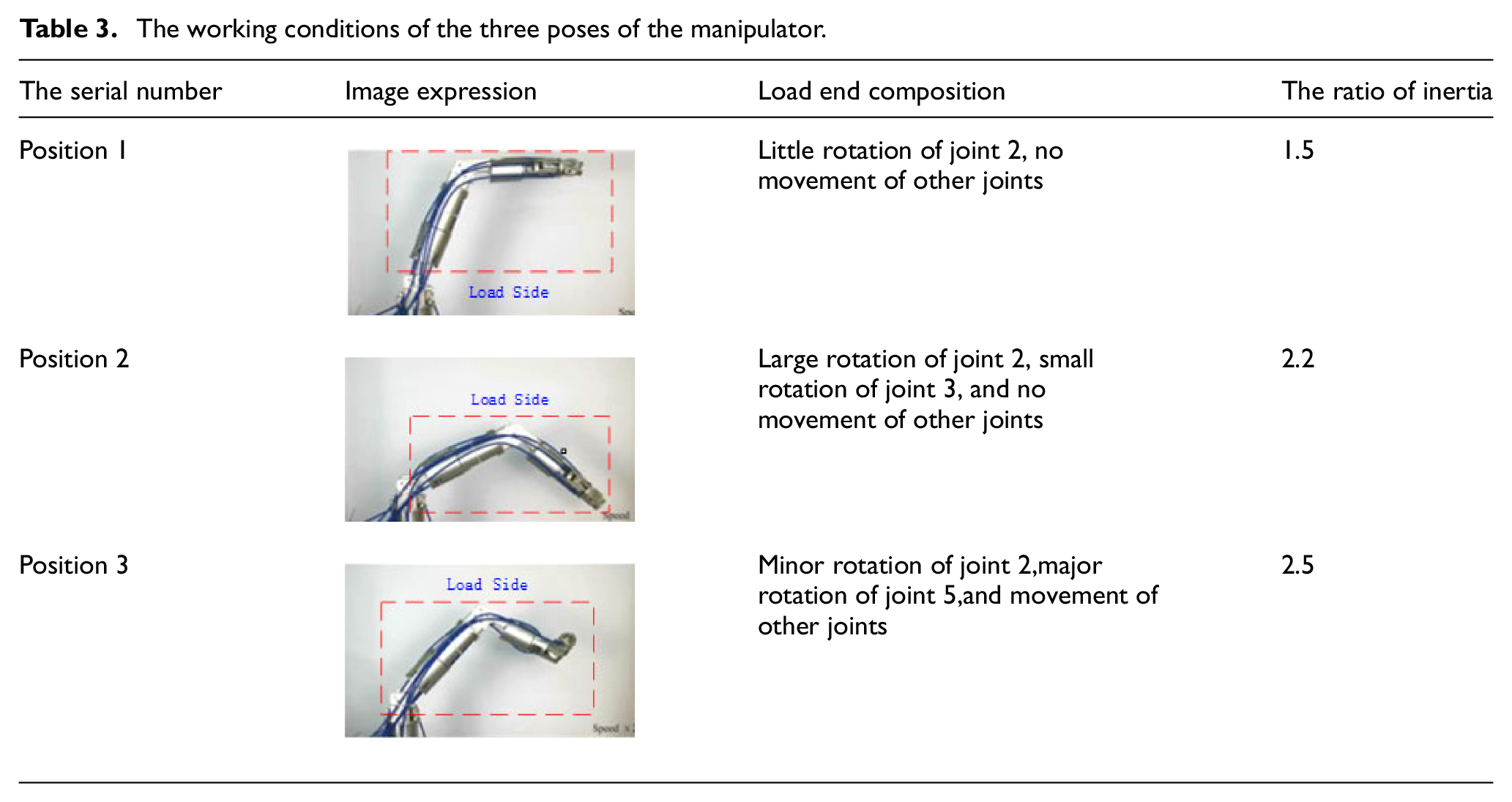
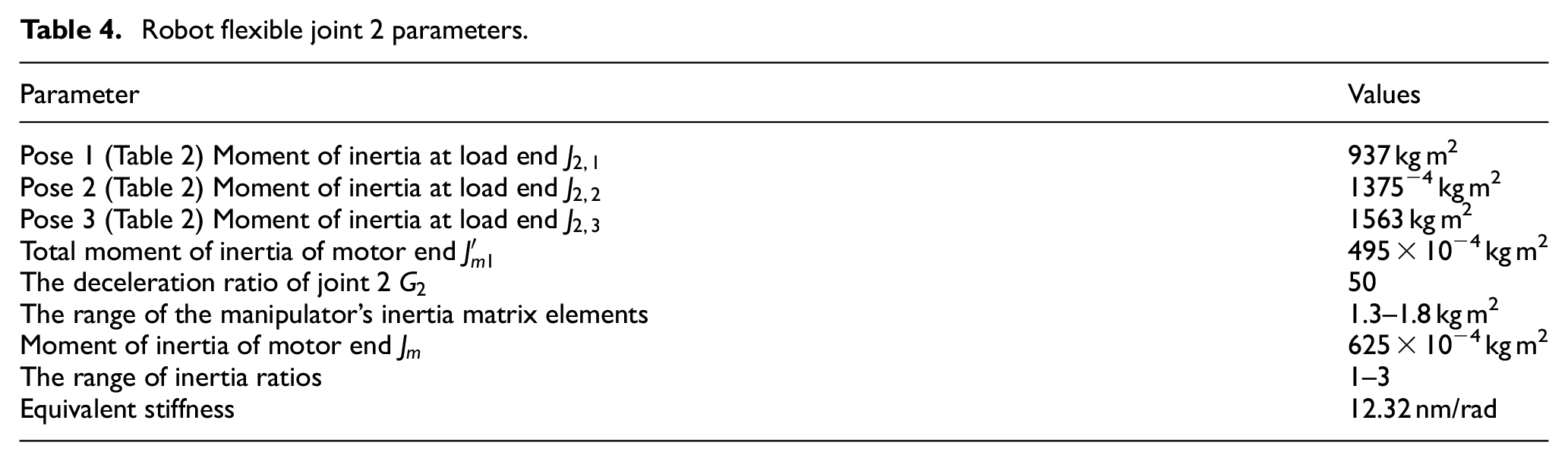
During the movement of the manipulator, each joint is in a different position (Figure 20). Three typical poses of joint 2 were selected for the experiment, and the working conditions were shown in Table 3. The parameters of the manipulator joint 2 are shown in Table 4.
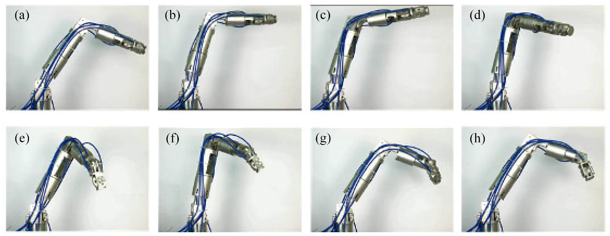
Movement process of the manipulator: (a)–(h) represent the motion sequence of the manipulator.
The working conditions of the three poses of the manipulator.
Robot flexible joint 2 parameters.
In this paper, Joint 2 of the manipulator is taken as the experimental object, and the load side is shown in Table 3. PD control and adaptive sliding mode control were used in the experiment, and the experimental results were shown in Figure 21. According to Figure 21, the actual sinusoidal tracking experiment of Joint 2 performed well. When using the sliding mode control strategy, the output displacement of manipulator Joint 2 is obviously better than that of PD control strategy.
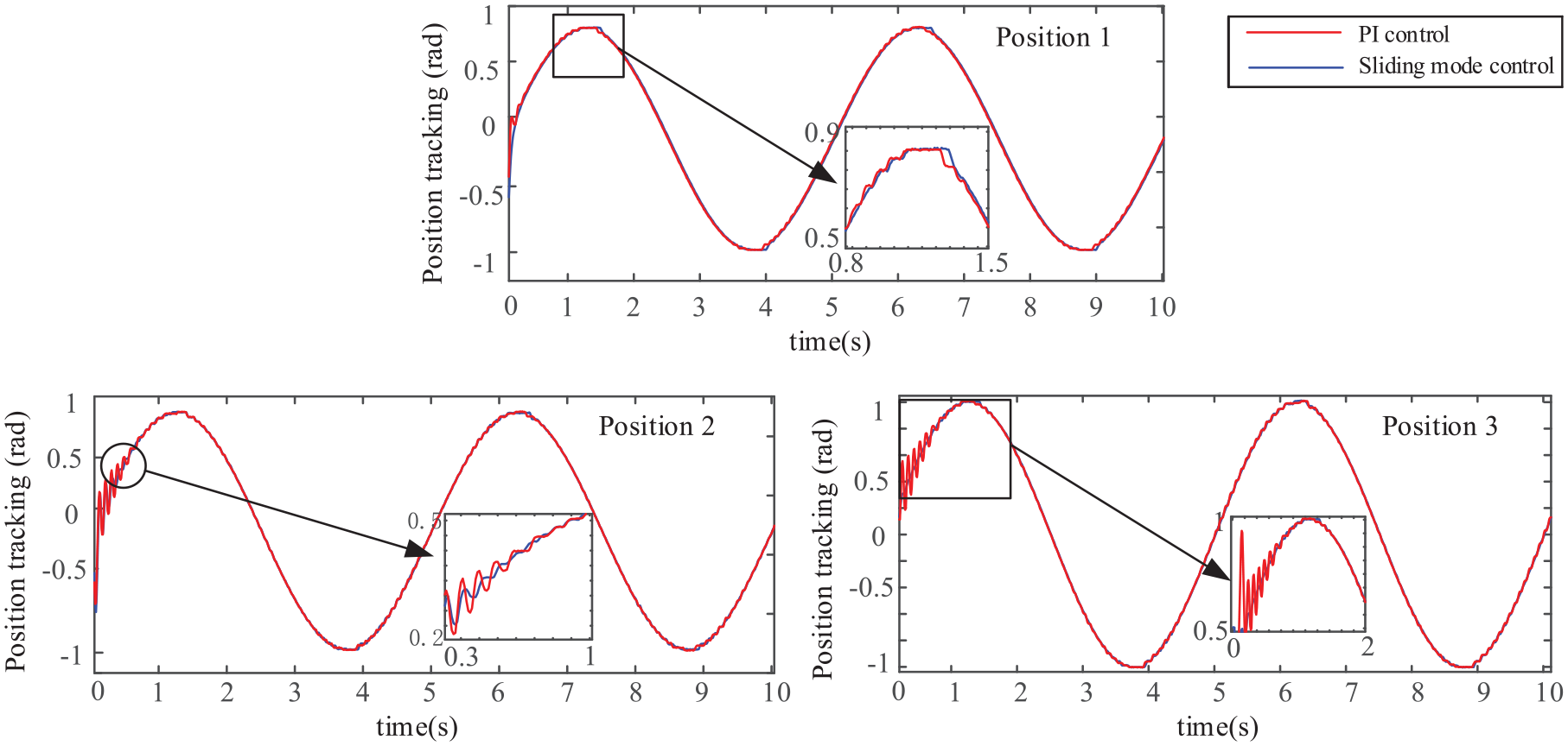
Angle tracking curve of joint 2.
According to Figure 21, when the ratio of moment of inertia increases gradually, the tracking effect of the manipulator is poor at the beginning. But as time goes, the manipulator can track the input signal stably. Adaptive sliding mode control can significantly improve the initial tracking performance of the manipulator. The tracking signal error of the second joint of the manipulator is shown in Figure 22.
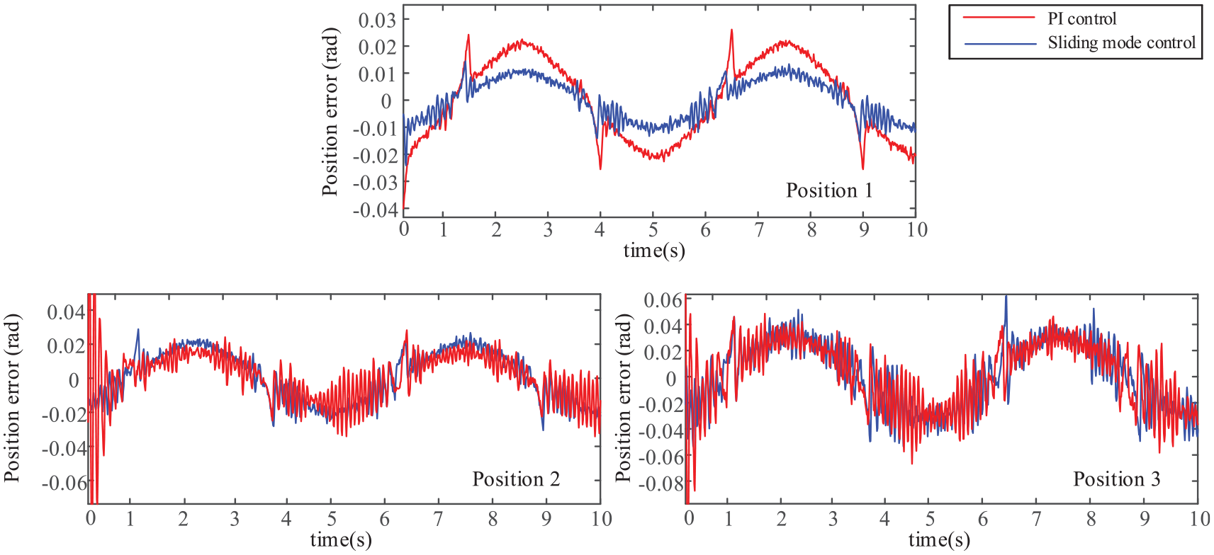
Angle tracking error of joint 2.
It can be seen from Figure 22 that the HJI slip-mode adaptive control strategy can significantly reduce the tracking error, has a faster convergence speed and higher tracking accuracy, and can improve the control performance of the system while ensuring the control input range, maintaining the robustness of the multi-joint robotic arm.
In this paper, the experimental error of each joint of the robot is analyzed and the experimental error curve is obtained, as shown in Figure 23. According to Figure 23, the control method proposed in this paper can effectively reduce errors.
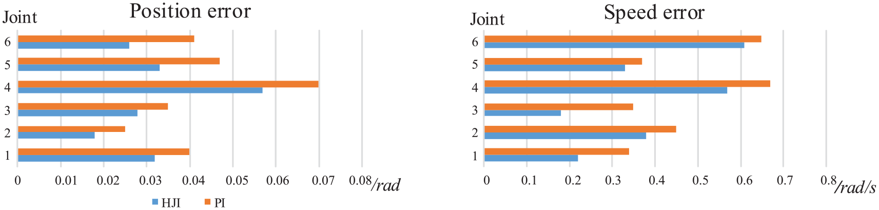
Error curve.
Conclusion
In this paper, the tendon-sheath drive is applied to manipulators, and a design scheme of 6-DOF light manipulators with motor rear is proposed. The configuration of the manipulator was determined by referring to the shoulder joint, elbow joint, and wrist joint of the human arm, and the driving module and manipulator joint were designed. According to the principle of flexible tendon-sheath, the dynamic model of flexible joint servo drive system of manipulator is established. In order to improve the motion control accuracy of the manipulator, an adaptive sliding mode robust control strategy based on HJI theory was proposed. Through stability analysis and simulation verification of the control strategy, the joint control experiment of the manipulator was conducted.
The effectiveness of the adaptive sliding mode robust control based on HJI theory is verified through experiments, and the following conclusions are drawn:
A dynamic model of a 6-DOF tendon-sheath manipulator is established. Based on the designed flexible tendon-sheath manipulator, the article analyzes the working space of the end effector through the D-H method, and the Lagrangian method was used to analyze the kinematics, then its dynamic model was established.
An adaptive sliding mode robust control strategy is designed. Based on the dynamic model of the tendon-sheath manipulator, the change characteristics of the load moment of inertia in the model are analyzed, and the optimized performance index function is established based on the HJI theory. The adaptive rate of the control parameters is designed based on the sliding mode control and the Lyapunov function The method proved the stability of the designed control strategy.
The effectiveness of the algorithm proposed in this paper is verified on the 6-DOF locking manipulator. Based on the control strategy designed in the article, the effectiveness was first verified by simulation; then a prototype was built for experiments, and the effect of commonly used PI controllers on interference suppression was compared, and the effect was significant. It can be expected that the adaptive sliding mode robust control strategy proposed in the article can play a good control role in the subsequent more complex motions of the 6-DOF telescopic manipulator.
Footnotes
Declaration of conflicting interests
The author(s) declared no potential conflicts of interest with respect to the research, authorship, and/or publication of this article.
Funding
The author(s) received no financial support for the research, authorship, and/or publication of this article.