
Abstract
A scheme to improve the structure of electromagnetic flow sensor is put forward in this paper, which can effectively solve the slurry noise problem when electromagnetic flowmeter measures slurry fluid. The electromagnetic flow sensor used for measuring slurry fluid has slurry noise interference in the measurement signal. At present, the method of increasing the excitation frequency of electromagnetic flow sensor is widely used to overcome slurry noise. However, high excitation frequency will lead to poor stability of zero point. In view of the shortcomings of existing methods, this paper studies the method of improving sensor structure to overcome slurry noise. Firstly, according to the mechanism of slurry noise, an improved scheme for the installation position of the measuring electrode of electromagnetic flow sensor is proposed, which can greatly reduce the probability of solid particles of slurry fluid colliding with the measuring electrode; Then, the relevant research results of bubble dynamics theory are applied to optimize the improvement scheme, and the improvement scheme is determined, through calibration, it is concluded that the improved sensor can reach the accuracy level of 1.0; Finally, through slurry measurement experiments, it is verified that the improved electromagnetic flow sensor can effectively overcome slurry noise.
Introduction
Problem of slurry noise
Slurry fluid belongs to liquid-solid two-phase flow, which widely exists on nature, energy, chemical industry, petroleum, mining, construction, water conservancy, metallurgy, environmental protection and other fields. The flow measurement of slurry fluid covers many fields of industrial production and engineering technology, such as hydraulic transportation of coal, ore, 1-4 transportation of coal water slurry in pipeline, 5-7 transportation of pulp in paper industry, 8,9 and sewage transportation. 10
The electromagnetic flow sensor has the advantages of simple structure, large measuring range, high measuring precision (the precision can reach 0.2%–0.5% of the indicated value), and good corrosion resistance. Moreover, there is no component in the measuring pipeline of the electromagnetic flow sensor that blocks the measured medium, which makes it more suitable for measuring slurry fluid. 11-14 Therefore, electromagnetic flow sensors are usually used to measure slurry fluid.
However, when electromagnetic flow sensor measures slurry fluid, there is slurry noise problem, which is reflected on the frequent beating phenomenon of measurement signal due to interference. 13-15 Interference in slurry noise on the measurement signal will lead to measurement errors, which will adversely to affect the measurement accuracy and stability. Therefore, it is necessary to study the problem of slurry noise and take measures to reduce or eliminate its influence on the measurement.
Research status of problem of slurry noise
With the wide application of electromagnetic flow sensors in slurry measurement, some flow research institutions and flow meter companies have made significant research work on slurry noise. Literature 14 illustrates the mechanism of slurry noise: slurry noise is caused by the impact of a large number of solid particles in the slurry fluid on the measuring electrode of an electromagnetic flow sensor. The research in reference 15-20 shows that the power spectral density of slurry noise is inversely proportional to the frequency and has 1/f characteristic. Based on the 1/f characteristic of slurry noise, signal processing method is used primarily to overcome slurry noise at present. The principle is as follows: the lower the frequency of slurry noise, the greater the noise intensity, and the higher the frequency of slurry noise, the smaller the noise intensity. So, increasing the excitation frequency of electromagnetic flow sensor can reduce the influence of slurry noise on the measurement signal.
With the application and progress of signal processing technology in various industrial fields, 21 using signal processing method to solve slurry noise problem has become an important research direction in the field of electromagnetic flow sensor. Cai 14 introduced the method of using high frequency rectangular wave excitation or dual frequency excitation to deal with slurry noise interference of the measurement signal. Toshiba Corporation 18,22,23 adopted high-frequency excitation method of electromagnetic flow sensor to solve slurry noise problem. Liang 16 used the slurry signal processing method of electromagnetic flowmeter based on signal model to process the slurry noise signal, the results show that this method can effectively weaken the slurry noise interference. Yang 19 designed a high-frequency square wave excitation scheme, using high-frequency square waves of excitation and adopting slurry signal processing method based on statistical analysis and signal reconstruction to overcome slurry noise and obtain stable flow output signal. Zhang 24 proposed a comb-like bandpass filtering and amplitude demodulation method to process the measurement signal of electromagnetic flowmeter under high frequency excitation, which can effectively to suppress the interference in slurry noise to the measurement signal, this method is based on high frequency excitation to solve the problem of slurry noise. The above research on slurry noise of electromagnetic flowmeter can effectively reduce the influence of slurry noise on the output signal, but using high excitation frequency will lead to poor stability of zero point of signal. 14
Li 25 proposed and invented an electromagnetic flowmeter with variable excitation frequency, which can change the excitation frequency according to the noise in the induced potential signal output by the electromagnetic flow sensor. The method mainly estimates the noise in the actual potential induced signal by changing the output signal of the sensor and changes the excitation frequency according to the intensity of the noise. When the noise is high, the excitation frequency increases, while when the noise is low, the excitation frequency decreases, so that the electromagnetic flowmeter not only has the ability to overcome the fluid noise caused by slurry but also can overcome the noise such as signal zero drifts, and can use the excitation frequency to estimate the slurry concentration value of the current fluid. Rosemond Company and Yokogawa Company 26,27 adopted compound excitation frequency mode and divided the induced potential signal output by electromagnetic flow sensor into two different frequency signal channels, high and low, and amplified them. If the slurry noise intensity is large, increase the weight of high frequency channel signal, and if the slurry noise intensity is small, increase the weight of low frequency channel signal. This dual-frequency excitation method can solve the slurry noise problem well, and the zero stability of the signal is also very good, but the excitation frequency is limited, so the excitation frequency cannot be increased indefinitely to reduce the influence of slurry noise on the signal. Pang 28 put forward a signal conditioning scheme for mixed digital and analog filtering method, and designed an electromagnetic flow sensor based on this scheme, which can be effectively to reduce all kinds of noise interference. However, this scheme can suppress all kinds of noise of electromagnetic flowmeter at a low flow rate, and the effect of reducing noise with this method at high flow rate is unknown.
Because slurry noise is caused by the impact of solid particles of slurry fluid on the measuring electrode, in order to solve the problem of slurry noise, some manufacturing companies of electromagnetic flow sensors make the surface area of the measuring electrode very small, which can reduce the number of times that solid particles of slurry fluid impact the measuring electrode surface per unit times, thus weakens the intensity of slurry noise and reducing the influence of slurry noise on the measuring signal. Although this method can reduce the influence of slurry noise on the measurement signal, it cannot completely eliminate slurry noise. In addition, reducing the electrode surface area will increase the internal resistance of the electromagnetic flow sensor because the internal resistance of the sensor will divide part of the measurement signal voltage, which will cause the loss of the measurement signal, and the larger internal resistance of the electromagnetic flowmeter will not be conducive to the measurement of low conductivity fluid. Therefore, the method of reducing the surface area of the measuring electrode cannot completely eliminate the slurry noise, and will also lead to the increase of the internal resistance of the sensor, which will bring adverse effects on the measurement.
The work and significance of this paper
To sum up, current research on slurry noise of electromagnetic flow sensor mainly uses signal processing method to eliminate the influence of slurry noise on measurement. At present, there is basically no research result to solve the problem of slurry noise by improving the structure of electromagnetic flow sensor. This paper puts forward a new idea to overcome slurry noise: based on the mechanism of slurry noise, the structure of electromagnetic flow sensor is improved to reduce slurry noise. The work in this paper will mainly explore new research space in these aspects.
The method in this paper has obvious application value in the field of liquid-solid two-phase flow measurement and the scheme for improving the sensor structures proposed in this paper to solve the slurry noise problem of electromagnetic flow sensor has the following significance: (1) It can improve the deficiency of the related research theory of electromagnetic flow sensor in the field of slurry measurement; (2) It provides a new idea and method for the study of slurry noise of electromagnetic flow sensor. (3) The proposal and application of a new method for electromagnetic flow sensor to overcome slurry noise will be more conducive to improving the accuracy and accuracy of slurry measurement, expanding the application range of electromagnetic flow sensor in the field of industrial production and engineering technology, such as ore pipeline transportation, coal water slurry flow measurement, and paper pulp flow measurement and playing a certain leading role in the development of flow meter industry.
Measurement principle and structure analysis of electromagnetic flow sensor
Measuring principle of electromagnetic flow sensor
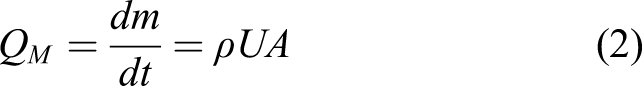
Flow sensor is a device for measuring fluid flows. The flow rate can be expressed by the following formula
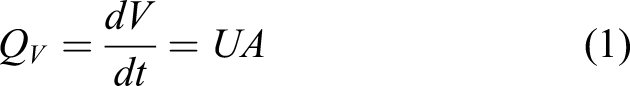
or
Electromagnetic flow sensor measures conductive liquid according to Faraday’s law of electromagnetic induction. The movement of conductive fluid in the magnetic field will produce an induced potential, which is proportional to the average flow velocity of fluid, as showed in Figure 1. Measuring principle of electromagnetic flow sensor.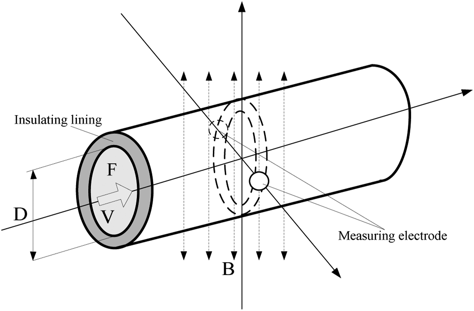
The measuring principle of electromagnetic flow sensor is shown in Figure 1, where

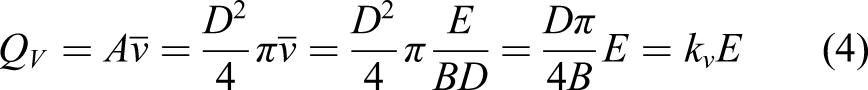
the flow rate can be calculated according to formula (1) and formula (3)
Causes of slurry noise
The electromagnetic flow sensor uses the measuring electrode to obtain the induced potential signal generated by the cutting magnetic line of the measured fluid to measure the flow. When measuring slurry fluid, solid particles collide with the surface of the measuring electrode, which will produce slurry noise.
The process of generating slurry noise is: in order to resist the corrosion of electrolyte, a thin oxide film is formed on the surface of electromagnetic flow sensor electrode when it comes into contact with fluid. In the process of forming the oxide film, polarization voltage is generated between metal and electrolyte. If the materials and surface states of the two electrodes are identical, the polarization voltage between the metal electrolytes becomes a common mode interference voltage with the same polarity and equal amplitude. When the solid particles or fibers in the liquid-solid two-phase fluid rub or impact the electrode surface, the thin oxide film on the electrode surface is torn or scratched, and the broken oxide film needs to be reformed. In the process of reforming the oxide film, the polarization voltage between the electrode and the fluid will suddenly change. If the materials, structures and surface states of the two electrodes are different, the polarization common-mode interference will be transformed into differential-mode interference, so the measurement signals obtained by the electrodes will fluctuate greatly, which will lead to the output signals of the electromagnetic flow sensor fluctuate greatly. 14
Obviously, as can be seen from Figure 1, the structure of the traditional electromagnetic flow sensor causes its measuring electrode to be easily collided by the solid particles of slurry fluid, resulting in slurry noise.
Structure analysis of electromagnetic flow sensor
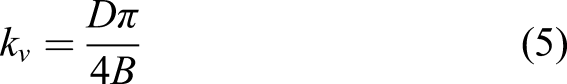
The installation structure of measuring electrode of traditional electromagnetic flow sensor is shown in Figure 2. Installation structure of measuring electrode of traditional electromagnetic flow sensor. 1- nut; 2- gasket; 3- lug plate; 4- insulation lining; 5- electrode; 6- metal conductor; 7- spring washer.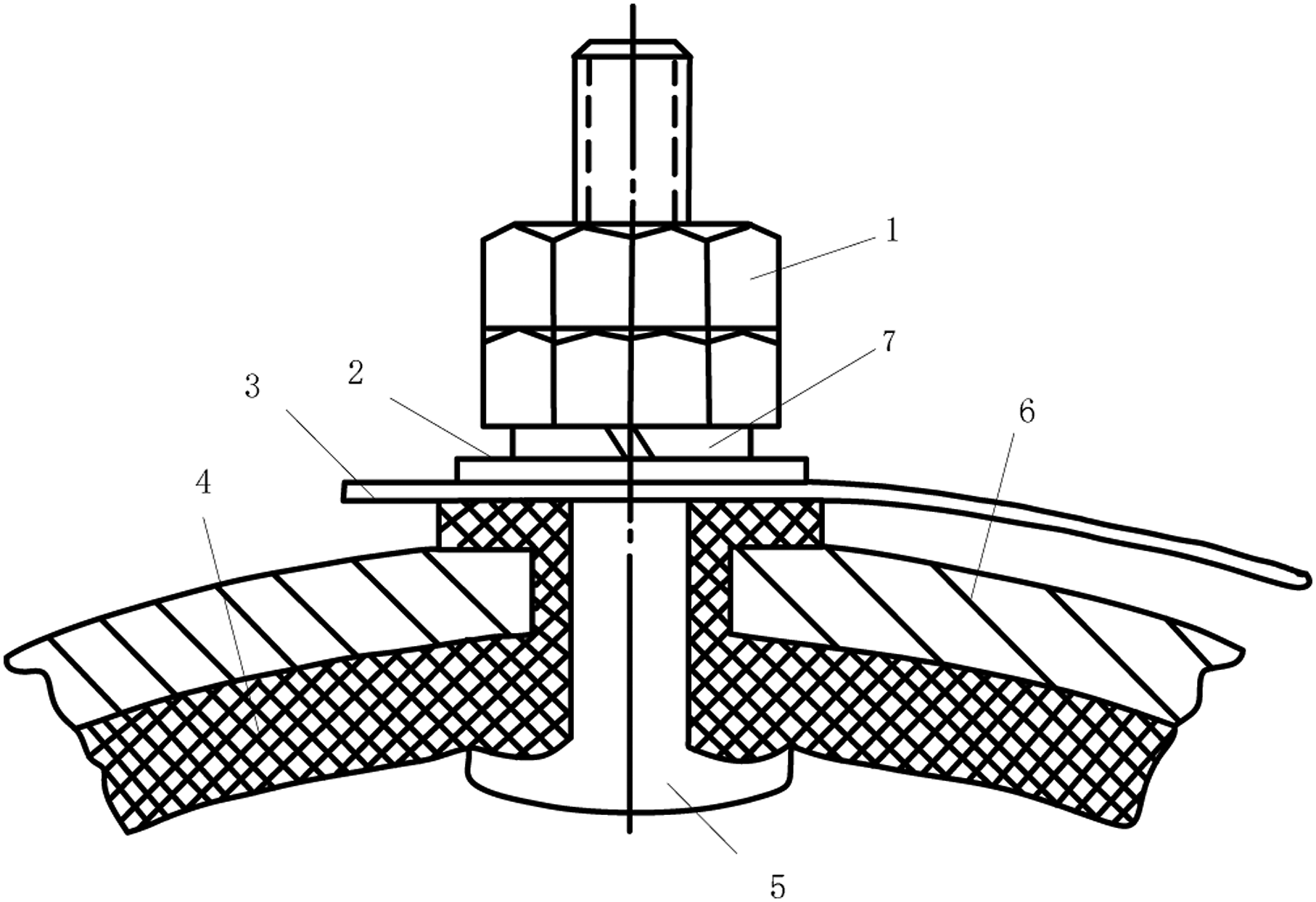
It can be seen from Figure 2 that the electrode surface of the traditional electromagnetic flow sensor is in direct contact with the fluid to be measured, so when the slurry fluid is measured, the solid particles of the slurry fluid collide with the electrode surface during the flow process, resulting in slurry noise.
At present, the electromagnetic flow sensor for slurry measurement produced by some electromagnetic flow sensor manufacturing companies has improved the installation structure of the measuring electrode, as showed in Figure 3. Installation structure of measuring electrode of electromagnetic flow sensor for slurry measurement. 1- nut; 2- gasket; 3- lug plate; 4- insulation lining; 5- electrode; 6- metal conductor; 7- spring washer; 8- insulating sleeve.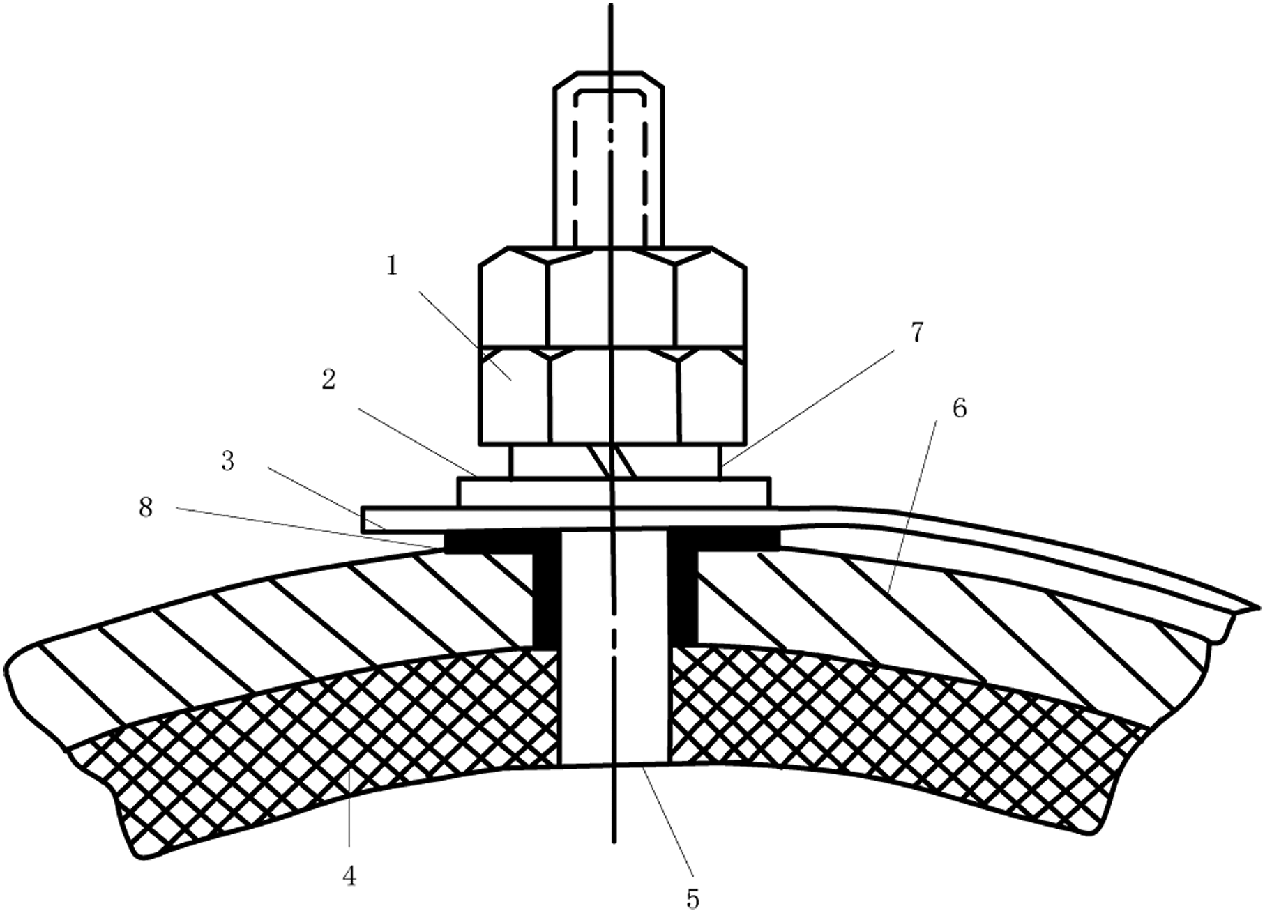
It can be seen from Figure 3 that compared with the common electromagnetic flowmeter, the installation structure of the measuring electrode of the slurry type electromagnetic flowmeter mainly improves the contact area between the electrode and the measured fluid, and the improvement mainly includes two aspects: (1) Changing the shape of electrode surface from hemispherical to flat head and reducing the area of contact surface between electrode and fluid; (2) Retract the contact surface between the electrode and the fluid towards the pipe wall, and the contact surface between the electrode and the fluid is flush with the surface of the insulating lining.
After the above improvement, the probability of solid particles colliding with the electrode surface can be reduced, thus reducing the influence of slurry noise on the measurement. These two improvements are aimed at decreasing the number of solid particles impacting the measuring electrode in unit time. However, because the contact surface between the measuring electrode and the measured fluid still exists, it is still impossible to completely avoid the collision of solid particles on the electrode surfaces when the electromagnetic flowmeter measures slurry fluid. Therefore, this improved method only reduces the impact of slurry noise on the measurement signal to a certain extent and does not fundamentally solve the problem of slurry noise. In fact, electromagnetic flowmeter for measuring slurry mainly adopts the method of increasing excitation frequency to solve the slurry noise problem at present.
If the structure of electromagnetic flow sensor is improved, it can greatly reduce or eliminate the number of solid particles colliding with electrodes per unit time without affecting the acquisition of measurement signals when measuring slurry fluid, which can effectively to reduce the intensity of slurry noise and achieve the purpose of overcoming slurry noise. In this way, various problems caused by the method of increasing excitation frequency to overcome slurry noise can be avoided. The improvement scheme for electromagnetic flow sensor to overcome slurry noise in this paper is based on this idea.
Improvement scheme of electromagnetic flow sensor
Proposal of improvement scheme
According to the previous analysis, the specific improvement scheme for the electromagnetic flow sensor is put forward as follows: change the installation position of the measuring electrode, so that the electrode surface and the insulating lining are not in the same plane, but in a relatively inner position. The insulating lining made of flexible material is between the electrode surface and the fluid. Within the area range of the electrode surface, several small holes are arranged on the insulating lining to communicate with the measured fluid, and the small holes are filled with the measured fluid. In this way, the measured slurry fluid flows in the magnetic field, and the electromotive force, i.e. the flow signal, generated by cutting the magnetic lines of force is picked up by the measuring electrode through the conductive fluid in the small hole, so that the surface of the measuring electrode is prevented from being directly collided by slurry solid particles, thus greatly reducing the probability of slurry solid particles colliding with the electrode, thus achieving the purpose of overcoming slurry noise. The electromagnetic flow sensor designed by the improved scheme is shown in Figure 4: Electromagnetic flow sensor designed by improved scheme. 1- nut; 2- gasket; 3- lug plate; 4- insulation lining; 5- electrode; 6- metal conductor; 7- spring washer; 8- small hole; 9- insulating sleeve.
As shown in Figure 4, the structure of the electromagnetic flowmeter sensor is improved, and the installation position of the measuring electrode is changed, so that the measured fluid does not directly contact the electrode surface, thus avoiding the collision of solid particles of the electrode. The flow signal is obtained by the measuring electrode through the conductive fluid in several small holes between the communicating electrode and the measured fluid. The improved scheme can overcome slurry noise without affecting the normal flow measurement.
Establishment of improvement scheme based on bubble dynamics
The above improvement scheme can greatly reduce the probability of solid particles colliding with the electrode, but the contact between the electrode and the fluid is realized through a plurality of tiny holes arranged on the insulating liner. If bubbles enter the small holes, or bubbles are generated due to the existence of the small holes and enter the small holes, this will lead to the electrode cannot obtain the induced potential, seriously affect the measurement. Therefore, how to determine the diameter and depth of the small hole between the electrode and the fluid needs to be studied.
If the surface area of the contact surface between the electrode and the measured fluid is

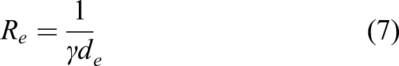
The input resistance of electromagnetic flowmeter is limited. According to Ohm’s law of the whole circuit, the internal resistance of flowmeter will divide part of signal voltage, which will cause the loss of the measurement signal. Obviously, if the internal resistance of flowmeter is reduced, the loss of measurement signal can be decreased. However, the internal resistance of flowmeter has nothing to do with the diameter of measuring tube. If the electrode area increases, the contact resistance between the medium and the electrode will decrease, so the internal resistance will further reduce, and the low internal resistance can measure the fluid with low conductivity. The relationship between internal resistance of flowmeter and electrode diameter can be seen in formula (7)
14
(1) The distribution of weight function is determined by the electrode area of electromagnetic flowmeter. Too large electrode area will cause the weight function
4,14
to become smaller near the electrode, which will weaken the flow signal; (2) When measuring slurry fluid, too large electrode area will increase the probability of solid particles colliding with electrodes, thus increasing the intensity of slurry noise.
Therefore, in the area of
At present, there are many research achievements, which have deeply explored and analyzed the generation, collapse and movement law of bubbles in the fluid. Tian 29 pointed out that in most gas-liquid two-phase systems, especially when the gas has faster dissolution rate and greater solubility, because the bubble floating speed is mainly determined by its radius, the change of bubble radius is controlled by gas diffusion and mass transfer and bubble pressure, and the gas diffusion and mass transfer rate is significantly affected by bubble floating speed and bubble radius, so the bubble floating and mass transfer process in liquid is a coupling process that influences and restricts each other.
The forces affecting bubble movement mainly include the following: (1) Buoyancy and gravity; (2) Viscous resistance; (3) Additional mass force; When bubbles accelerate in liquid, not only the velocity of bubbles changes but also the velocity of the liquid around them changes, and the force needed to drive these liquids to accelerate is the additional mass force. (4) Basset force;
Basset force is instantaneous flow resistance when bubbles accelerate in viscous fluid, which is directly related to the movement process of bubbles.
Zhang A.M 30 studied the causes and process of bubble rupture, and pointed out that the actual causes of bubble rupture are very complex, which usually have the following main aspects: First, the bubble is in turbulent vortex, and the bubble is easy to rupture under the collision of turbulent vortex. The second is that the volume of large bubbles increases to a critical value, and the surface tension is not enough to continue to maintain the shape of large bubbles, resulting in collapse or rupture. Third, steady bubbles are disturbed by external forces. Fourthly, the bubbles near the wall will split into two sub-bubbles under the interaction of the Bjerknes force and buoyancy, when the Bjerknes force on the wall is equal to the opposing buoyancy. These research conclusions show that there is a possibility that bubbles will enter the small holes before they break, thus affecting the measurement.
Zhang J.W 31 studied the motion law of bubbles in fluid, and pointed out that the motion of bubbles in fluid is a very complex physical process, which includes many coupling processes such as compressibility, viscosity, surface tension, heat conduction, gas diffusion and thermodynamic effect, and has strong nonlinearity and instability. As for the radial movement of bubbles, when bubbles move in static fluid, the change of radius is influenced by hydrostatic pressure, bubble surface tension, gas diffusion rate on the bubble surface, concentration of dissolved gas in fluid and other factors.
Liu
32
analyzed the force acting on bubbles in water, studied the movement law of bubbles along the vertical direction, and assumed that the water around the bubbles was static and the bubble diameter (1) Bubbles in water exist objectively; (2) The movement process of underwater bubbles is rapid acceleration, and the acceleration gradually decreases until it is approximately zero; (3) In the past, predecessors thought that the final velocity of bubbles was relative and could only be regarded as near constant velocity, but when the water depth reached a certain depth, the velocity curve was obviously curved, indicating that the final velocity of bubbles was not constant velocity; (4) When the speed reaches nearly constant speed, the acceleration rises slightly, and the greater the water depth, the more obvious it is; (5) The velocity of bubbles with the same diameter reaching the water surface is equal regardless of the maximum water depth, and the larger the bubble diameter, the faster the velocity. (6) The value of the acceleration section is very small, which is related to the bubble diameter. It is about 3 (7) The rising velocity of larger diameter bubbles obtained from experiments is bounded. When
Zhang J.S
33
ignores the internal motion of bubbles, and obtains the dynamic equation of small bubbles (

The above research on the movement law of bubbles in water shows that in the electromagnetic flowmeter measurement pipeline, the radius and shape of bubbles in the fluid at the bottom or center of the pipeline will change during the movement, and may enter the small hole, thus affecting the contact between the fluid and the electrode and affecting the measurement. However, the research conclusions of Liu and Zhang J.S are drawn under the condition of still water, and there is a difference between these conclusions and the movement law of bubbles when electromagnetic flowmeter measures flowing fluid.
Wang 34 proposed two methods for calculating the rising bubble volume in two-phase flow. One is to construct an ellipsoid equivalent to the bubble volume according to the shape of the bubble, which is called geometric method; the other is to deduce the formula for calculating the bubble volume according to Newton’s second law by analyzing the force of the bubble in the vertical direction, which is called force analysis method. According to these two calculation methods, the volume of bubbles in the pipeline can be obtained, and the diameter of the small hole can be designed so that bubbles cannot enter the small hole.
Yin
35
studied the process of bubble formation and collapse, and got some conclusions as follows: (1) Analytical solution of spherical bubble radius changing with time: (2) The calculation results of the collapse process of two bubbles with different initial radii show that the change rate and degree of bubbles with relatively small radius are greater than those with relatively large radius, and the two bubbles go through two stages of collapse and rebound alternately; The maximum jet velocity in the velocity fields to appear outside the small bubble, and the centroid position of the big bubble is almost unchanged when the small bubble approaches the big bubble. With the increase of the radius ratio, the deformation degree of small bubbles increases, and the pressure gradient inside the two bubbles increases significantly. (3) By comparing and analyzing the collapse process of multiple bubbles in the flow field, the collapse starts from the outer bubble and propagates from the outside to the inside, and the farther away from the central bubble, the greater the change rate and deformation degree of bubbles. However, the central bubble is restrained by ambient air, and its change rate is slow at first and then fast. With the increase of void ratio, the time required for the first collapse is prolonged, and the maximum pressure at the centroid increases significantly when it reaches the minimum volume.
These conclusions can describe the process of bubble generation in the electromagnetic flowmeter measuring pipeline flow field, and it can be seen that the higher the density of the measured fluid, the longer the time required for bubble collapse, that is, the higher the density of the measured fluid, the greater the impact of bubbles. The change rates and the degree of small bubbles are larger than those of relatively large bubbles, so the relationship between the change rate and bubble diameter should be considered when set the diameter of small holes under different pipe diameters.
Liu 36 summarized the main bubble forms in the pipeline and expounded the characteristics of these forms. It can be used as the theoretical basis for studying the bubble characteristics in the pipeline measured by electromagnetic flowmeter.
Yuan
37
noted that bubbles are mainly produced by gas crushing and jet bubbling. As for the formation of bubble in orifice, this document points out that gas passes through a small hole and enters a certain thickness of the liquid layer, which is similar to the situation of a liquid jet in air. Because of the different gas velocity, there are two states: when the gas velocity is low, discrete single bubbles are formed, when the gas velocity is high, a continuous gas jet is formed, and then the jet breaks and bubbles of different sizes are formed. When air flows through the orifice to form bubbles, the pressure in the bubbles decreases due to the upward movement of the bubble centroid and the decrease of capillary pressure, so the gas flow rate may change with time. Generally speaking, bubble formation goes through two stages: expansion stage and detachment stage. In the first stage, the bubble expands and its bottom remains in contact with the orifice. In the second stage, the bottom of the bubble moves upward from the orifice and contacts the orifice with a thin neck, finally forming bubbles, and the bubble volume (1) Buoyancy (2) Surface tension. The additional force caused by surface tension is calculated by the following formula (3) Viscous force. Viscous force is the resistance of bubbles. In this study, due to the low flow rate of gas itself, viscous force can be ignored. (4) Inertial force. When the outflow gas flow rate is constant, the bubble expands at a corresponding rate, and the momentum change caused by it is the inertial force of the bubble.When calculating the bubble size, if the gas flow rate is low, viscous force and inertial force can be ignored, and only buoyancy and surface tension can be considered, and the calculation formula of bubble diameter can be derived, so that


According to the above analysis, in the measurement pipeline, the main factors affecting the bubble size of the measured fluid are: the flow rate of the measured fluid, the diameter of the small hole on the insulation lining, and the physical properties of the measured fluid. By fluid with certain physical properties and pore diameter, when the gas flow rate increases, the bubble volume increases, and when the gas flow rate is very low, it can be considered that the bubble volume is not affected by the flow rate. The pore diameter has a significant influence on the bubble size, and the surface tension provides a significant constraint force. With the increase of pore diameter, the bubble increases. The physical properties that affect bubble size mainly include viscosity, density and surface tension of liquid, while the effects of density and viscosity of gas can be ignored.
According to the bubble generation principle put forward in reference,
36
the reasons of bubble generation in the pipeline measured by electromagnetic flow sensor can be summarized: the bubble generation in the small hole near the electrode of the improved electromagnetic flow sensor is due to the turbulent diffusion of fluid. After the liquid flows into the small hole, the original gas is sucked and compressed, the liquid surface generates friction with the surrounding air, the liquid particles are transposed with the air particles, and the air is sucked into the liquid and taken away by the liquid, thus causing further negative pressure on the surrounding air to form a local vacuum, and more surrounding air is sucked into the liquid, thus continuously circulating. Because of the large tolerance between gas and liquid, the motion situation is complicated. In reference
36
, the movement process of liquid flowing through small holes is divided into three stages: (1) Relative movement away liquid and gas.
Because of the viscous action between liquid and gas, the liquid brings gas into the small hole, both liquids and gas is continuous media, and there is relative movement away from them. Due to the influence of external disturbance, the liquid appears pulsation and surface wave after a short distance from the entrance into the tiny holes. (2) Gas-liquid mixing movement section.
Under the influence of the turbulent diffusion of liquid, the amplitude of the fluid surface wave in small holes increases continuously. When the amplitude radius is larger than the fluid radius, a large amount of gas is dispersed into the liquid under the action of shear force, and the impact and collision between liquid and gas molecules transfer energy to the gas, which accelerates and compresses the gas. (3) Bubble generation section.
The gas is crushed and divided into many tiny bubbles and dispersed in the liquid. As the kinetic energy of the mixed liquid passing through the pores is converted into potential energy, the pressure rises and the gas is further compressed, divided and reduced. At this point, the bubble has been formed.
To sum up, in the improved electromagnetic flowmeter measuring pipeline, when the measured fluid flows through the tiny hole, a large number of bubbles will enter the small hole, thus affecting the electromagnetic flowmeter to pick up the flow signal. Therefore, improvement schemes proposed in this paper need to consider the influence of bubbles generated in the measured fluid on the measurement.
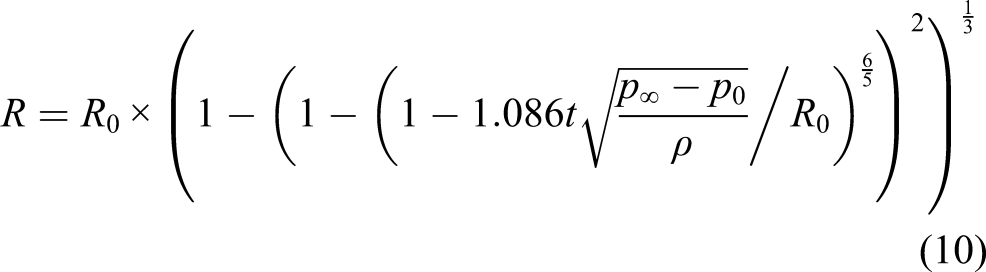
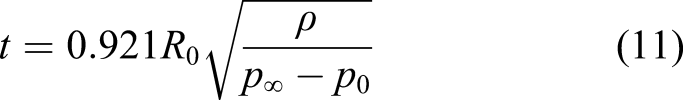
According to formulas (15) and (16), the volume of bubbles can be calculated. Obviously, the volume of bubbles is determined by the diameter of pores and the physical properties of liquid such as density and viscosity. Therefore, it can be seen that bubbles exist objectively in pores and the shorter the collapse time, the smaller the impact on the measurement. Therefore, according to formulas (10) and (11), the time required for the bubble diameter to change with time and decrease to zero can be approximately calculated. It can be seen that when the density of the measured fluid is constant, the smaller the diameter
In this study, because the electrode diameter of the experimental electromagnetic flow sensor is 8
According to the above improvement scheme, the electromagnetic flow sensor used in the experiment is made, as showed in Figure 5. Improved electromagnetic flow sensor structure. 1- nut; 2- gasket; 3- lug plate; 4- original insulation lining; 5- electrode; 6- metal conductor; 7- spring washer; 8- small hole; 9- newly added insulation lining.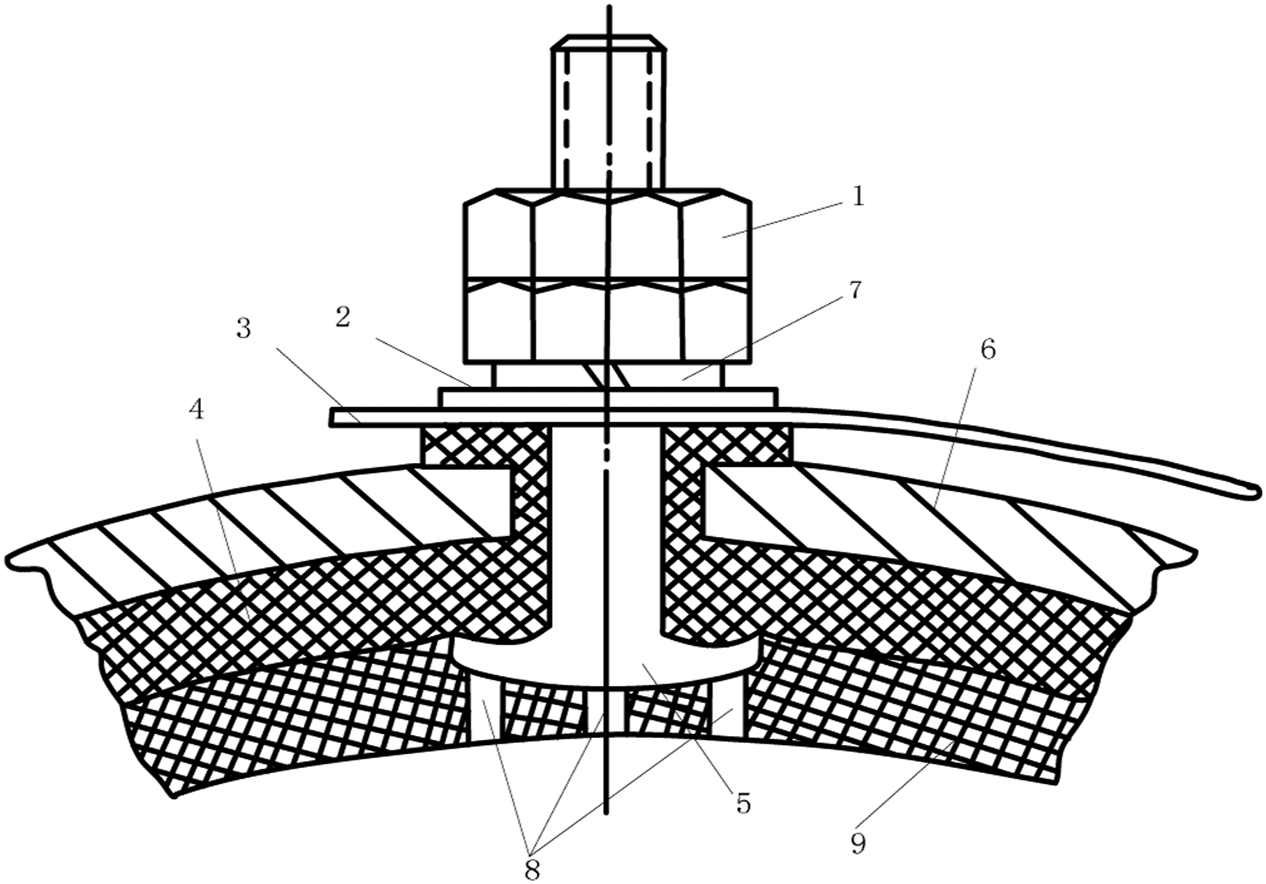
As showed in Figure 5, an insulating liner with thickness of 10
Experimental verification
The electromagnetic flow sensor is manufactured according to the improved scheme, and its caliber is 40 (1) Calibrate the improved electromagnetic flow sensor on the calibration device, get the accuracy, repeatability and error of the sensor, and verify that the improved sensor can measure the flow correctly. (2) Using the same converter for the improved electromagnetic flow sensor and the traditional electromagnetic flow sensor, the slurry fluid is measured at excitation frequencies of 3.125 Hz, 6.25 Hz and 12.5 Hz respectively. The average flow velocity of slurry fluid is set to
Calibration test experiment
Figure 6 is a simplified system component diagram of flow sensor calibration device used in this experiment. Calibration device of flow sensor.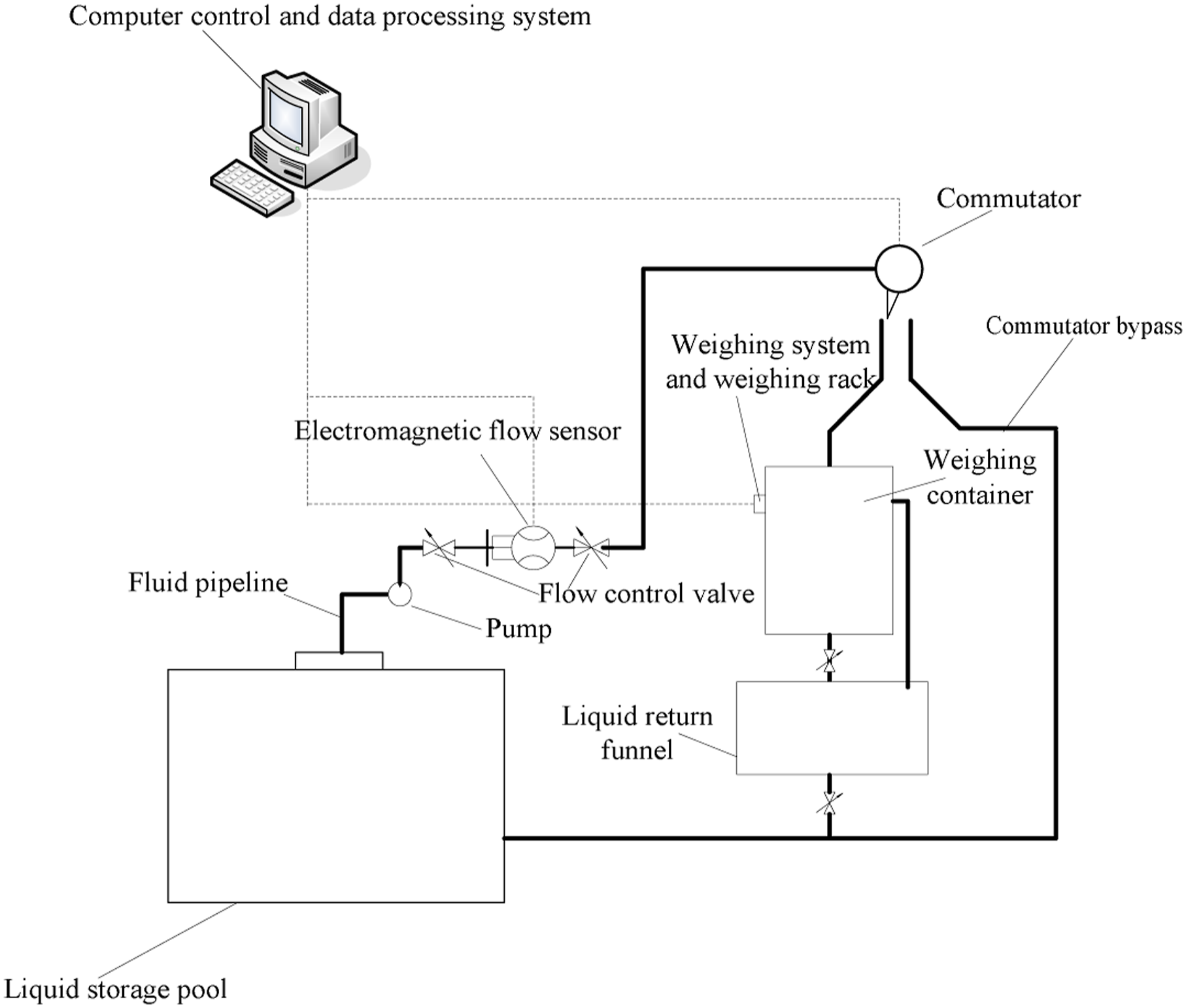
The working process of flowmeter automatic calibration control system is as follows: (1) Determine the caliber, maximum range and other parameters of the flowmeter to be verified. Install the flowmeter to be inspected on the corresponding caliber pipeline. (2) Start the computer control system on the console, and input parameters such as caliber and maximum range of the flowmeter to be verified, then open the flow control valve, start the water pump, and let the water enter the pipeline. (3) The flow regulating valve is controlled by computer, so that the flow through the regulating valve reaches a specific flow point. (4) After the water flow reaches stability in the pipeline, first hit the commutator to the right to make the water bypass the commutator, and then hit the commutator to the left. At this time, the water will enter the weighing container, and the two valves under the weighing container will automatically close with the operation of the commutator. (5) After a certain period of time, operate the commutator and turn it to the right again. At this time, the computer will collect the weight of the weighing container and the verification time, and finally calculate the parameters such as accuracy, repeatability and error.
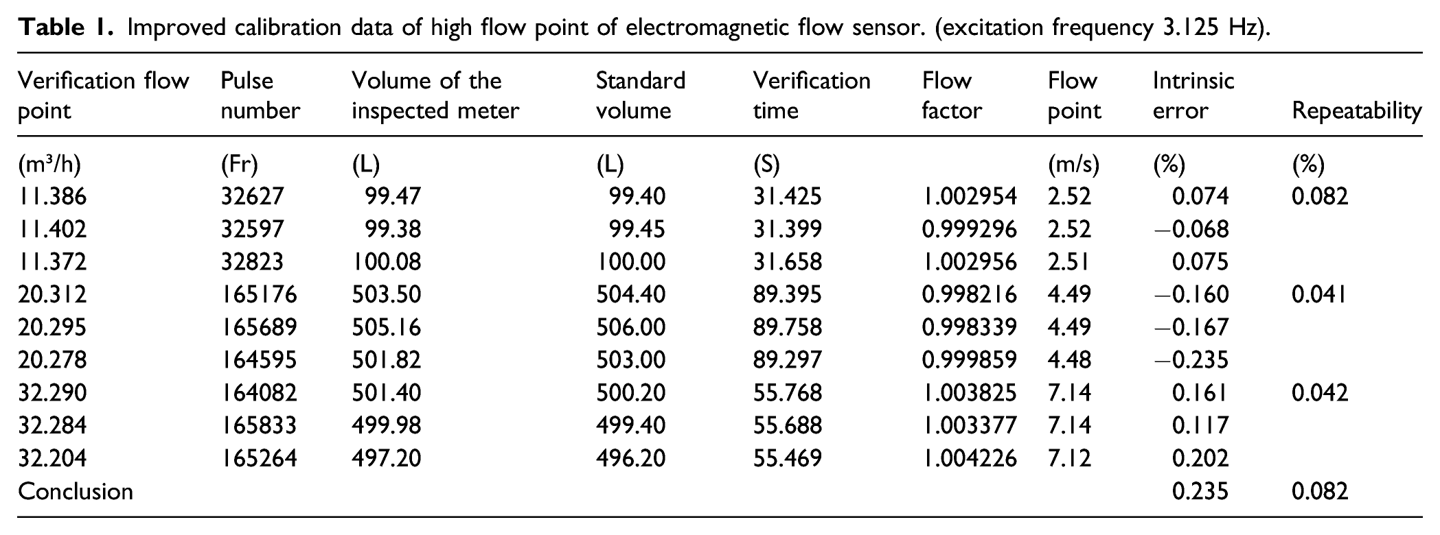
Improved calibration data of high flow point of electromagnetic flow sensor. (excitation frequency 3.125 Hz).
Improved calibration data of low flow point of electromagnetic flow sensor. (excitation frequency 3.125 Hz).
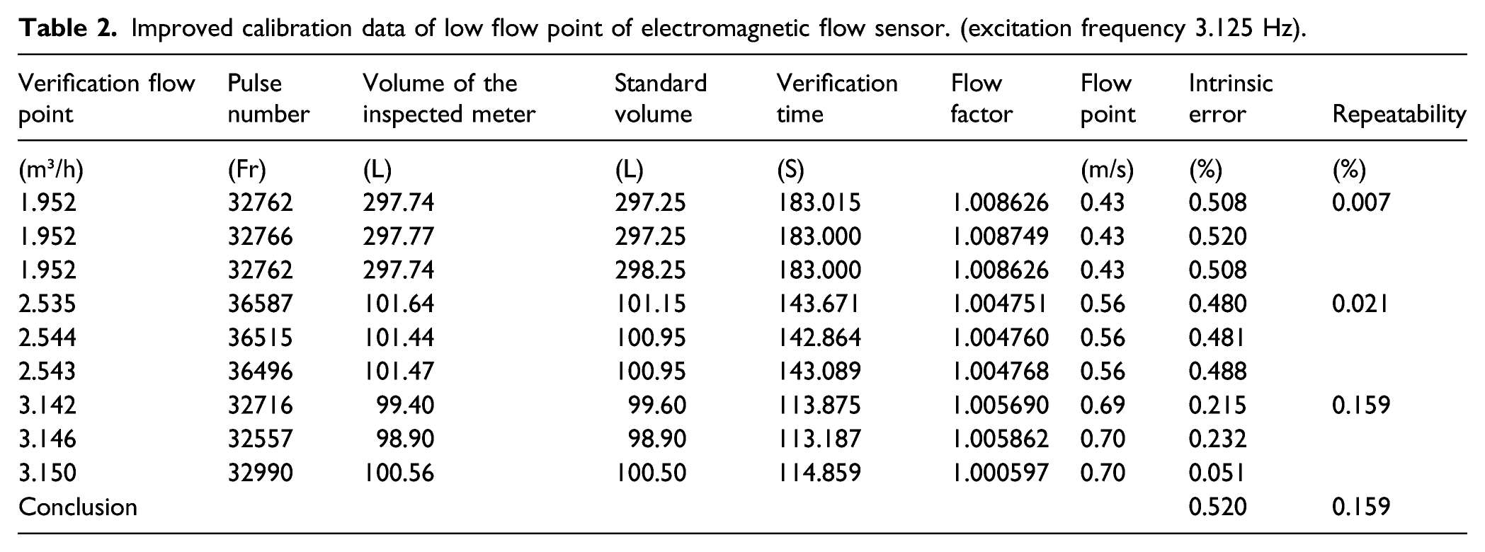
Table 1 shows the calibration of three high flow points of the improved sensor with excitation frequency of 3.125 Hz. It can be seen that the maximum repeatability is 0.082%, which is less than the 0.1% repeatability required by 0.3-level instrument accuracy. The maximum error is 0.235%, which (is less than the 0.5% error required by 0.5-level instrument accuracy, and both repeatability and error meet the accuracy requirements of 0.5-level instrument.
Table 2 shows the calibration of three low flow points of the improved sensor with excitation frequency of 3.125 Hz. It can be seen that the maximum repeatability is 0.159%, which is less than the 0.167% repeatability required by 0.5-level instrument accuracy. The maximum error is 0.520%, which is less than the error of 1% required by the accuracy of 1.0-level instrument. Through nonlinear correction, it can meet the accuracy requirement of 0.5-level instrument.
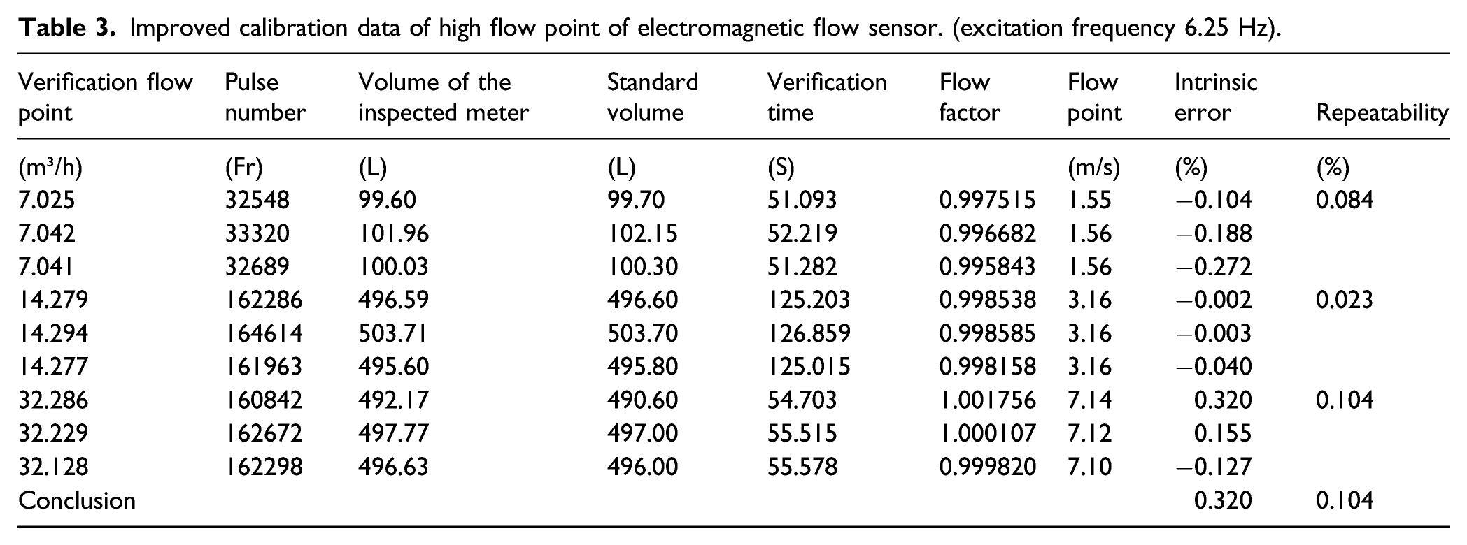
Improved calibration data of high flow point of electromagnetic flow sensor. (excitation frequency 6.25 Hz).
Improved calibration data of low flow point of electromagnetic flow sensor. (excitation frequency 6.25 Hz).
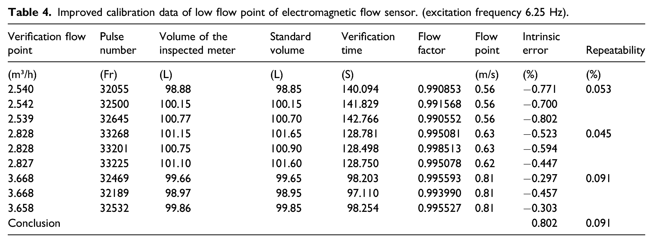
Table 3 shows the calibration of three high flow points of the improved sensor under the excitation frequency of 6.25 Hz. It can be seen that the maximum repeatability is 0.104%, which is less than the 0.167% repeatability required by the 0.5-level instrument accuracy; The maximum error is 0.320%, which is less than the error of 0.5% required by the accuracy of 0.5-level instrument, and both repeatability and error meet the accuracy requirements of 0.5-level instrument.
Table 4 shows the calibration of three low flow points of the improved sensor under the excitation frequency of 6.25 Hz. It can be seen that the maximum repeatability is 0.091%, which is less than the 0.1% repeatability required by the 0.3-level instrument accuracy; The maximum error is 0.802%, which is less than the error of 1% required by the accuracy of 1.0-level instrument. Through nonlinear correction, it can meet the accuracy requirement of 0.5-level instrument.
Improved calibration data of high flow point of electromagnetic flow sensor. (excitation frequency 12.5 Hz).
Improved calibration data of low flow point of electromagnetic flow sensor. (excitation frequency 12.5 Hz).
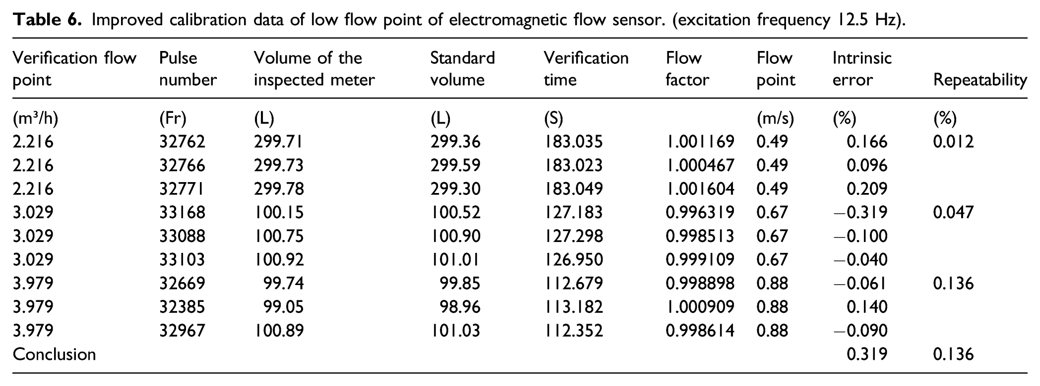
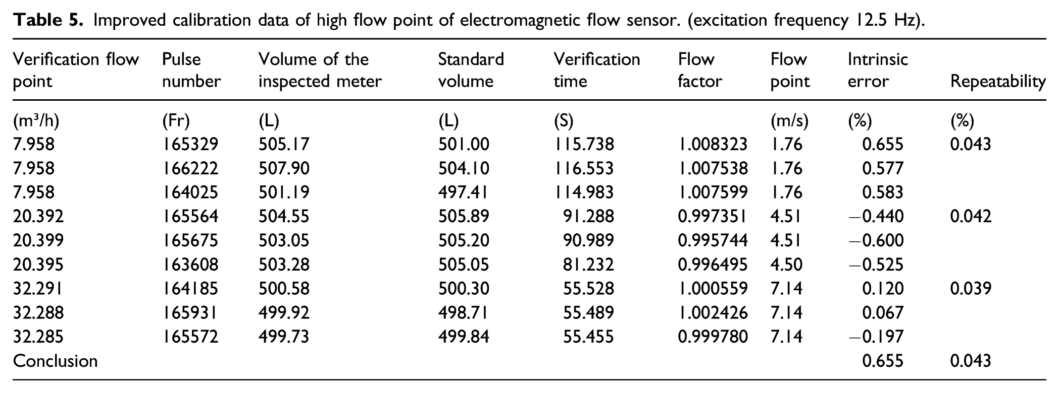
Table 5 shows the calibration of three high flow points of the improved sensor under the excitation frequency of 12.5 Hz. It can be seen that the maximum repeatability is 0.043%, which is less than the 0.1% repeatability required by the 0.3-level instrument accuracy; The maximum error is 0.655%, which is less than the error of 1% required by the accuracy of 1.0-level instruments, and can meet the accuracy requirements of 1.0-level instruments.
Table 6 shows the calibration of three low flow points of the improved sensor under the excitation frequency of 12.5 Hz. It can be seen that the maximum repeatability is 0.136%, which is less than the 0.167% repeatability required by the 0.5-level instrument accuracy; The maximum error is 0.319%, which is less than the error of 0.5% required by the accuracy of 0.5-level instrument, and both repeatability and error meet the accuracy requirements of 0.5-level instrument.
To sum up, the calibration results of six flow points at excitation frequencies of 3.125 Hz, 6.25 Hz, and 12.5 Hz show that the improved sensor can meet the accuracy of 1.0-level.
Surry flow measurement experiment
The slurry experiment device is shown in Figure 7. Slurry flow measurement experiment with improved sensor.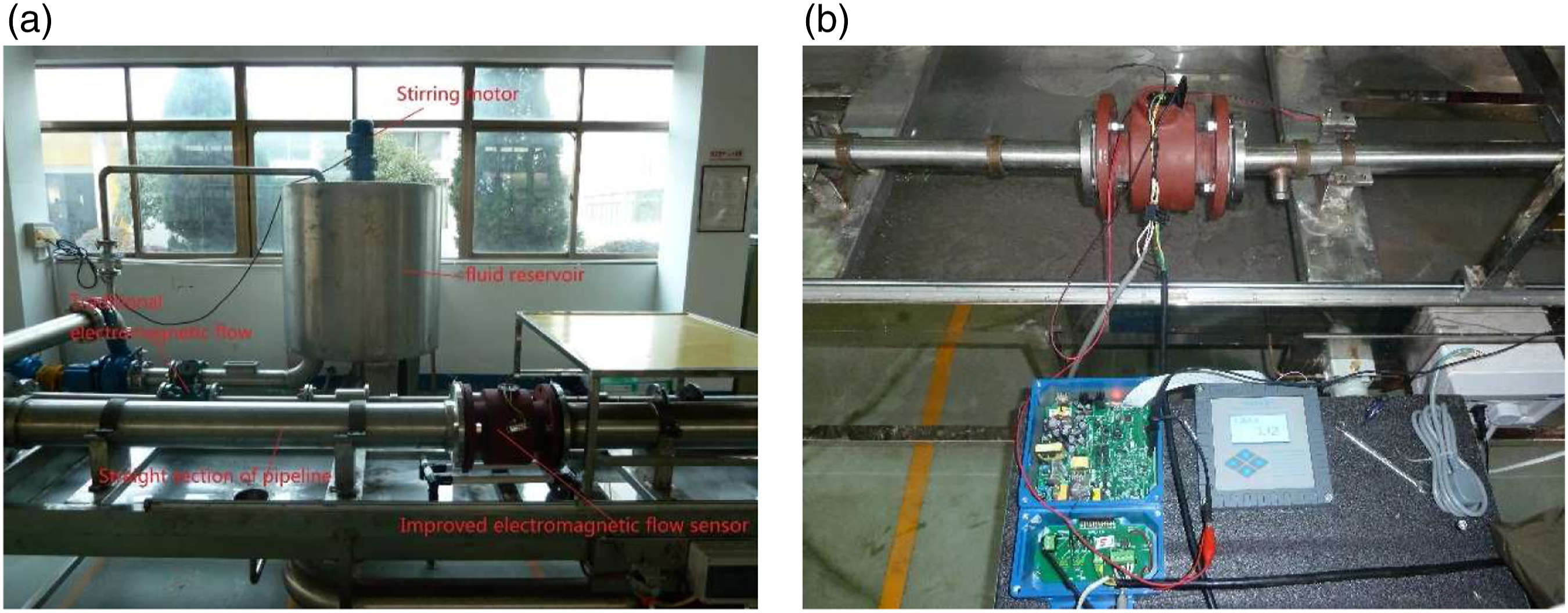
As showed in Figure 7, the improved sensor is installed on the experimental device, and the traditional electromagnetic flow sensor is installed on the experimental device for comparison. In order to prevent the flow rate from being unstable, it is necessary to reserve a long enough straight pipe length upstream of the sensor installation position. 38,39 The two sensors adopt the same converter, by comparing the measurement waveforms of the improved sensor and the traditional sensor, it is verified that the improved sensor can better overcome the influence of slurry noise on the measurement signal.
There are some problems needing attention in the experiment: the improved sensor is changed from 60
In the experiment, pulp is used as slurry fluid, the average solid concentration is 5%, and the excitation mode is three valued rectangular wave excitation. When the excitation frequency is 3.125 Hz and the average flow velocity is 1 Sensor flow rate induced potential signal waveform (excitation frequency 3.125 Hz, average flow velocity 1 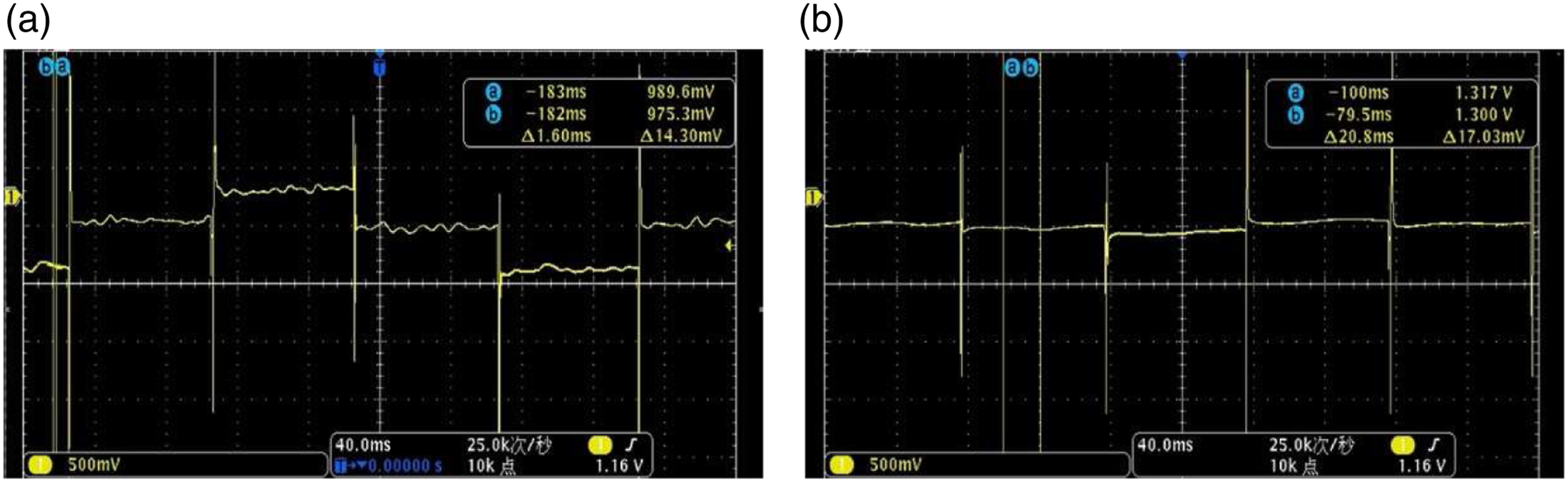
Figure 8(a) is the flow velocity induced potential waveform of the traditional sensor, and Figure 8(b) is the flow velocity induced potential signal waveform of improved sensor. It can be seen that the flow velocity induced potential signal waveform of traditional sensor is obviously interfered by slurry noise, while the flow velocity induced potential signal waveform of improved sensor is little affected by slurry noise. When the average flow velocity increases to Sensor flow rate induced potential signal waveform (excitation frequency 3.125 Hz, average flow velocity 3 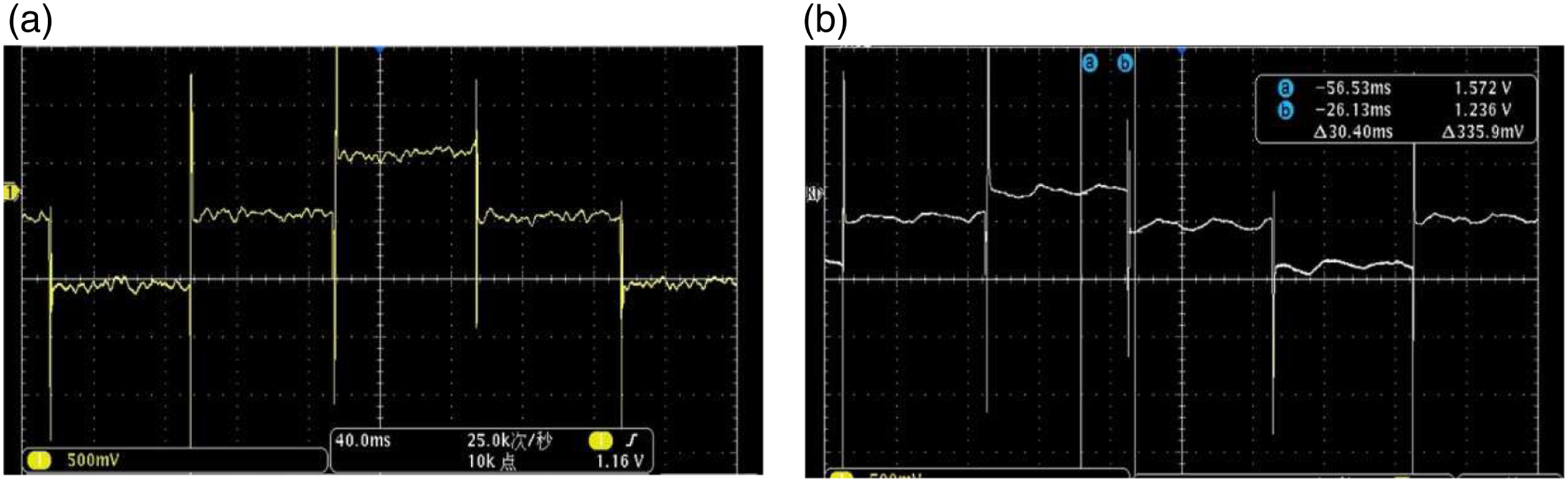
It can be seen from Figure 9 that when the average flow velocity of fluid increases to 3
When the excitation frequency is 6.25 Hz and the average flow velocity is 1 Sensor flow rate induced potential signal waveform (excitation frequency 6.25 Hz, average flow velocity 1 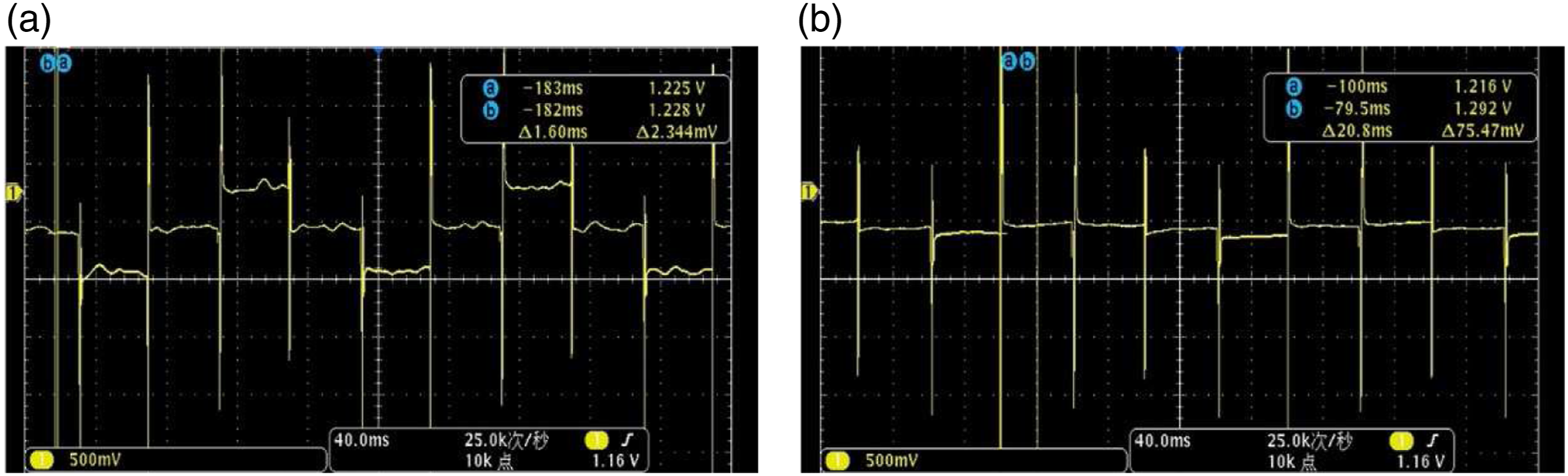
It can be seen from Figure 10 that when the excitation frequency is 6.25 Hz and the average flow rate is 1 Sensor flow rate induced potential signal waveform (excitation frequency 6.25 Hz, average flow velocity 3 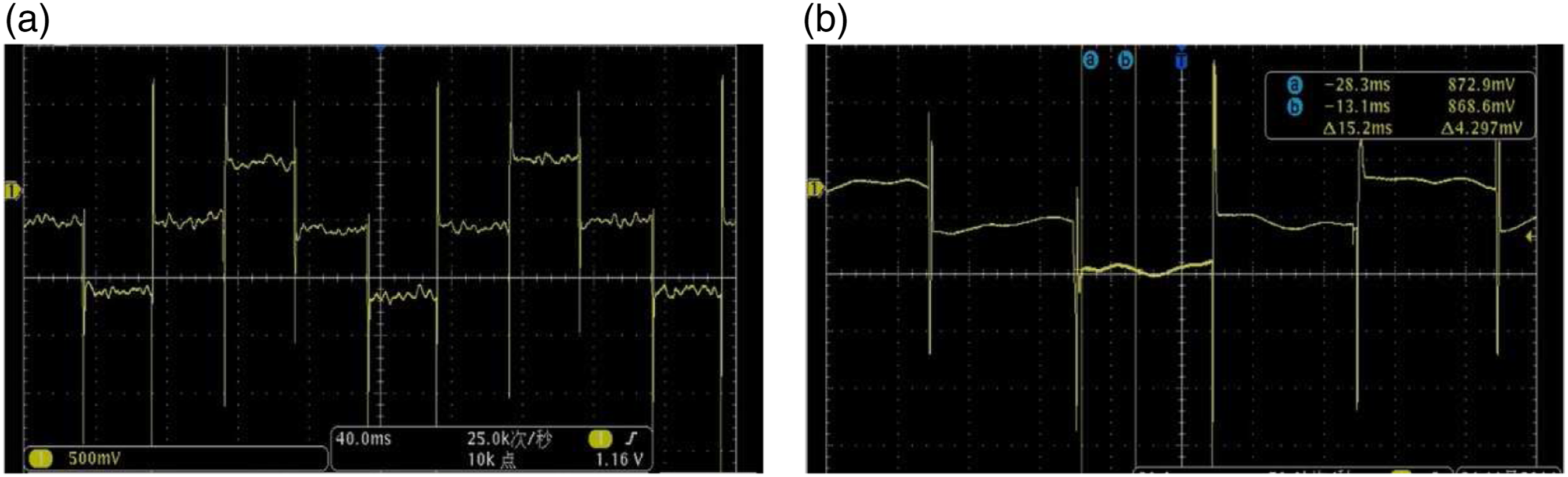
It can be seen from Figure 11 that when the average flow velocity of fluid increases to 3 Sensor flow rate induced potential signal waveform (excitation frequency 12.5 Hz, average flow velocity 1 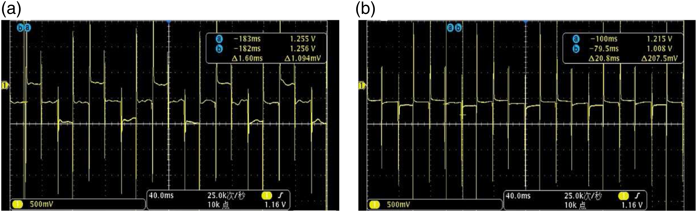
It can be seen from Figure 12 that when the excitation frequency is 12.5 Hz and the average flow velocity is 1 Sensor flow rate induced potential signal waveform (excitation frequency 12.5 Hz, average flow velocity 3 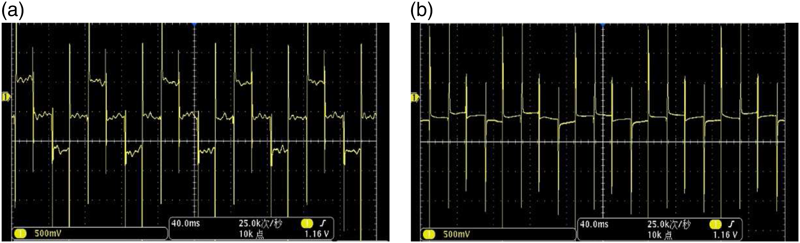
It can be seen from Figure 13 that when the average flow velocity of fluid increases to 3
Discussion of experiment
By comparing the improved electromagnetic flow sensor with the traditional electromagnetic flow sensor, it can be concluded that the improved electromagnetic flow sensor can overcome slurry noise. Specifically, it includes the following aspects: (1) When electromagnetic flow sensor measures slurry fluid, the velocity induced potential signal will be interfered by slurry noise. With the increase of average velocity, the interference degree of velocity induced potential signal by slurry noise increases. (2) With the increase of excitation frequency, the interference degree of velocity induced potential signal of traditional electromagnetic flow sensor by slurry noise decreases, but the interference degree of velocity induced potential signal waveform of improved sensor is still greater than that of slurry noise at the same frequency. In addition, increasing the excitation frequency will reduce the stability of the zero point of the sensor
14
, so the method of increasing the excitation frequency cannot fundamentally solve the slurry noise problem. (3) Under the same excitation frequency and the average flow velocity, the interference degree of flow velocity induced potential signal of improved flow sensor by slurry noise is much less than that of the traditional electromagnetic flow sensor.
To sum up, when measuring slurry fluid, the traditional electromagnetic flow sensor is obviously interfered by slurry noise. Even if the excitation frequency is increased, the influence of slurry noise cannot be completely avoided, and the stability of zero point will be reduced. After improving the sensor structure with the scheme in this paper, the influence of slurry noise can be significantly reduced, and the problem of poor stability of sensor zero point caused by increasing excitation frequency can be avoided.
Conclusion
Aiming at the slurry noise problem of electromagnetic flowmeter when measuring slurry fluid, this paper proposes a scheme to overcome slurry noise by improving the structure of electromagnetic flow sensor and makes an electromagnetic flow sensor according to the improved scheme. Through calibration and slurry measurement experiments, it is verified that the improved scheme of electromagnetic flow sensor proposed in this paper can better overcome the interference of slurry noise to flow signal. Experiments show that, compared with the traditional electromagnetic flow sensor, the improved electromagnetic flow sensor can significantly overcome the interference of slurry noise at lower excitation frequency (3.125 Hz–12.5 Hz).
The contribution of this paper lies in: At present, research on electromagnetic flow sensor for slurry flow measurement is mainly about the solution of slurry noise, and these research results mainly focus on using signal processing methods to eliminate the interference of slurry noise. Through improving the structure of electromagnetic flow sensor, this paper tries to explore the research space and achievements of new solutions to slurry noise. The test results show that the electromagnetic flow sensor, which can be used for slurry measurement, can overcome the influence of slurry noise. It is helpful to perfect the research theory of slurry electromagnetic flow sensor.
There are still some shortcomings in this study, which need further study, as follows: (1) The electromagnetic flow sensor model and bubble dynamics model in this paper are established under ideal conditions, and the measured fluid flow state is stable. Some possible interference factors, such as temperature and electromagnetic interference, are ignored. If the influence of these factors is considered, the reliability of measurement should also be studied. (2) In the improvement scheme of this paper, the research on the factors affecting the measurement is limited to the experimental conditions. At present, according to the principle of bubble dynamics, the influence of bubble generation and movement on the measurement is considered, and the improvement scheme is established accordingly. There are other factors that affect the measurement in practical application, such as the blocking factor of solid particles, the vortex caused by slurry in the flow and the change of internal resistance of the sensor. Future work should further consider other factors affecting measurement in the improvement scheme, so as to supplement and improve the improvement scheme in this paper. (3) The experimental verification work is limited by conditions, and only one caliber electromagnetic flow sensor is selected to study the improvement scheme; In the aspect of slurry fluid, only pulp fluid is selected, and few flow points are selected. In the future work, electromagnetic flow sensors with various calibers, slurry fluids of different types and multiple flow points can be selected for experiments, so as to better find and analyze problems and meet the needs of practical engineering.
To sum up, the model establishment and experiment in this paper were completed under ideal conditions, ignoring the influence of some interference factors. In further research, the model and experiment should be improved better.
Footnotes
Declaration of conflicting interests
The author(s) declared no potential conflicts of interest with respect to the research, authorship, and/or publication of this article.
Funding
The author(s) disclosed receipt of the following financial support for the research, authorship, and/or publication of this article: This work was sponsored by the Henan province key research and development and promotion special (No. 192102110204) and the national natural science foundation of China under Grant (No. 61805073).