
Abstract
Rotary Inverted Pendulum (RIP) mimics the behavior of many practical control systems like crane mechanism, segway, unicycle robot, traction control in vehicles, rocket stabilization, and launching. RIP is a fourth-order nonlinear open-loop unstable dynamical system and is widely used for testing the effectiveness of the newly developed control algorithms. In this paper, a Hybrid Control Scheme (HCS) based on energy balance and fuzzy logic controllers is proposed to implement the swing up and stabilization control of RIP. In the proposed control scheme, the fuzzy logic-based state feedback gains are dynamically tuned in real-time by minimizing the absolute error between the desired and actual states to get robust control performance. The proposed HCS is also compared with the conventional Linear Quadratic Controller (LQR) for this application. The comparative results show that the proposed fuzzy logic-based hybrid control scheme gives the optimal control performance in terms of achieving satisfactory transient, steady-state, and robust responses from a given RIP system, as compared to the conventional LQR based control scheme. The proposed control scheme is also relatively less complex with a low computational cost and provides desired response characteristics as compared to the existing ones in the literature.
Keywords
Introduction
A Rotary Inverted Pendulum (RIP) is a multivariable nonlinear control system typically of fourth order and is inherently an unstable system. The design of a stable and reliable control system for such a complex system is a challenging problem and is used as a test-bed for the development of new control algorithms for many other complex nonlinear engineering applications.1–3 It is an important control problem in modern control theory since it imitates the behavior of many practical control systems like crane mechanisms, segway systems, unicycle robots, traction control in vehicles and rocket stabilization, and launching.4,5 Till now many algorithms have been suggested in the literature to control the dynamics of RIP but still, it is being extensively investigated and new control algorithms are being developed. 6 Simulation studies of the inverted pendulum based on PID controllers were presented in Wang. 7 Krishen and Becerra 8 developed fuzzy methods for control of the RIP. Swing-up and LQR stabilization of a rotary inverted pendulum was proposed in Park et al. 9 Fractional-order PIλDμ controller design was discussed in El-Khazali. 10 The controller design for rotary inverted pendulum system using evolutionary algorithms was reported in Hassanzadeh and Mobayen 11 and the particle swarm optimization-based controller was reported in Hassanzade and Mobayen. 12 Yu 13 designed a control system for the fourth-order dynamic system that involved modeling, analysis, and analog controller design.
He presented the mathematical model of a RIP along with its analysis by designing an Analog controller to control the dynamics. The effects of the control approach were studied using numerical simulations. He et al. 14 developed a robust control for a RIP considering the active disturbance attenuation. The design of the state recurrent wavelet-based cerebellar model articulation controller was proposed for RIP by the Chiu and Peng. 15 The proposed algorithm was implemented with real RIP using Arduino mega 2560 controller and RIP was balanced at an inherently unstable point. Likewise in Yang and Zheng, 16 the swing up and stabilization control problem of RIP was designed and implemented using trajectory planning and nonlinear adaptive neural network control techniques.
Wang et al., 17 derived a mathematical model of RIP using the Euler-Lagrange equation, and then two different control schemes were designed using fractional-order and integer-order PID controllers (IOPID). From the experimental results, it was found that fractional-order PID (FOPID) gives better performance as compared to the IOPID. Similarly, the RIP was driven by following the desired navigation instruction instructed by the operator in Pujol-Vazquez et al. 18 In this technique, external magnetic perturbations are seen as external commandments. To maintain the upright position of the RIP along with the free movement of the base of RIP, an H-infinity controller was designed and tested experimentally.
Horibe and Sakamoto 19 proposed a stable manifold method by solving the Hamilton-Jacobi equation for the swing up and stabilization control of RIP. Experiments were included for two controllers (one swing and two swings). The proposed technique in this paper provided an analysis method for the investigation and enlargement of the stable manifold. Sainzaya et al. presented the control, that is, swing up and balance control using the LQR and the PID controllers with experiments. 20 Shi et al. 21 investigated the network-based event-triggered control of RIP with quantization. To stabilize the RIP, H-infinity based controller was designed. Using the stabilization criterion, the quantized state feedback controller was designed. Han and Lee 22 presented designed balancing and speed-based control of a unicycle robot using a dynamic model. Two independent controllers were designed to balance the roll axis and pitch axis (speed control). First SMC was applied onto the roll axis to stabilize the robot and the linear quadratic controller was applied to track the reference speed command. Li et al., 23 the type two fuzzy systems having different membership functions were analyzed using state and output feedback. The same member function was not shared by the type-two fuzzy logic model and state and output feedback controller. The effectiveness of the FLC and output feedback controller was proved using the RIP system. For the mobile wheeled RIP system, a new disturbance observer was designed in Ri et al. 24 Optimal gain vectors were also calculated for a better estimate of disturbance observer.
The backstepping control scheme was implemented in Chiu 25 by decoupling the position and angle of the Two-Wheeled Inverted Pendulum (TWIP). It is a nonlinear system of fourth-order and for this system, asymptotic stability was achieved by using proposed backstepping control. Reddy et al. 26 used a firefly algorithm to design the optimal PID controller using pole placement to meet the given time-domain design specifications. A fractional order-based stability control for a system of the single link RIP was presented by Liao et al., 27 Lagrange equation along with G-L fractional-order calculus was used to derive the mathematical model. Both integer-order and fractional-order PID controllers were designed and values of proportional, integral, and derivative gains were calculated for RIP. Peng et al. 28 presented an innovative optimal technique for a humanoid-based balancing robot to regulate ankle stiffness. The proposed technique was designed using Integral Reinforcement Learning (IRL), which was developed using only limited knowledge of the system dynamics. Hazem et al., 29 proposed Fuzzy-LQR and Fuzzy-LQG techniques for double-link rotary inverted pendulums and computed various response parameters such as rise time, settling time, and steady-state errors. Gani et al., 30 a control system for the four state variables (angular position of inverted pendulum, angular velocity of inverted pendulum, cart position, and cart velocity) was designed to simultaneously balance the inverted pendulum and place the cart in the desired position with Sugeno inference method based fuzzy logic controller. A real-time HIL control system on rotary inverted pendulum hardware platform based on double deep Q-network was presented in. 31 An adaptive model predictive control of a two-wheeled robot manipulator with varying mass was proposed in Önkol and Kasnakoğlu. 32 In Ouyang et al., 33 the control research was done on the rotary crane systems with double-pendulum effect to achieve the positioning of the boom and the suppression of the load sway.
In this paper, our contribution is the development of a hybrid control scheme based on energy balance, and fuzzy logic controller to implement the swing up and stabilization control of RIP. In the proposed control scheme, the fuzzy logic-based state feedback gains are dynamically tuned in real-time by minimizing the absolute error between the desired and actual states to get robust control performance. The said control scheme is practically implemented and tested using a National Instruments QNET RIP board. To analyze the performance of the proposed control scheme in comparison to the existing standard control techniques, swing up, and stabilization control of the same RIP system is also implemented by using the hybrid control scheme based on energy balance and conventional LQR controller. A comparison of the proposed technique with the existing technique demonstrated the superior performance of the proposed scheme. The main advantage of the proposed hybrid control is a relatively less complex implementation with a low computational cost of the control algorithm as compared to many existing ones. The novelty of the proposed work is the theoretical design and practical implementation of the proposed hybrid scheme. No such experimental study has been reported in the literature up to our best knowledge.
Further contents of the paper are organized as follows: mathematical modeling of RIP is performed in Section 2, controller designs are discussed in Section 3, results and discussions are presented in Section 4, and finally, conclusions are described in the last section.
Dynamical modeling of RIP
Mathematical model of RIP
In this study, the Euler Lagrange method has been used to derive the dynamical model of the RIP. Figure 1 shows the RIP board on which the experiment has been performed.

RIP board.
Figure 2 illustrates the equivalent model of the RIP board.
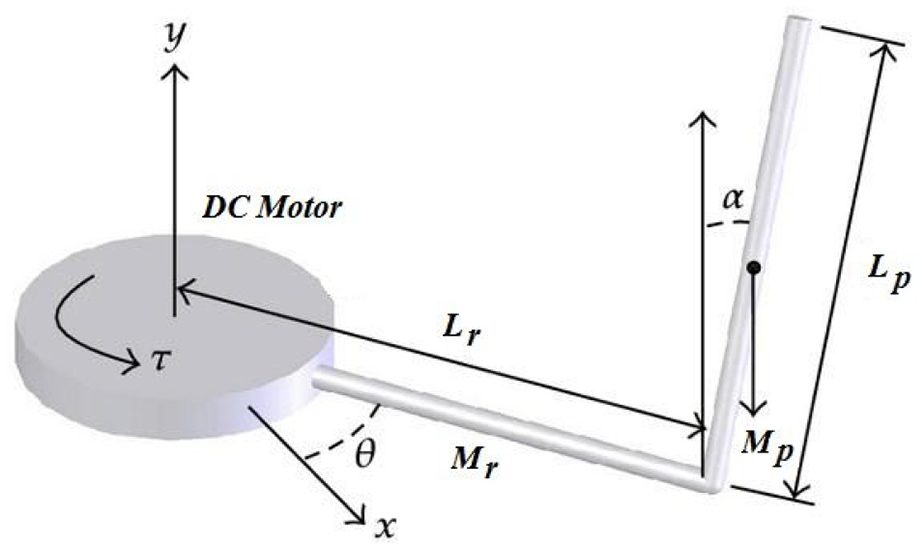
Free body diagram of RIP.
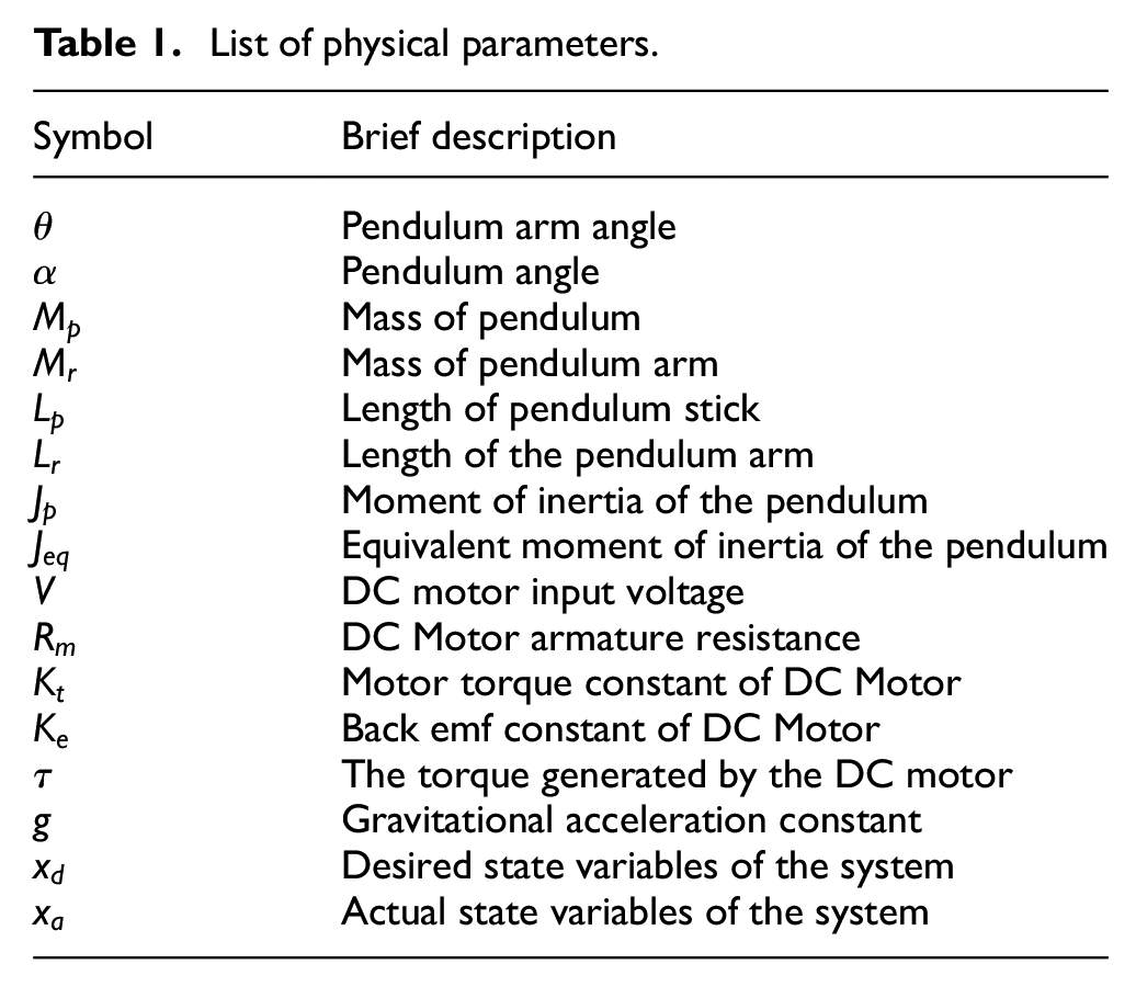
Table 1 lists the physical parameters used in deriving the model of the dynamical system.
List of physical parameters.
From Figure 2, the equations describing the x–y coordinates of the pendulum position regarding its base are:


To find velocity components, taking the derivative of (1) and (2) respectively gives:


The speed of the pendulum arm along the x-coordinate is given as:

So, using (3) to (5), the velocity components of a pendulum along the x and y direction are written as:


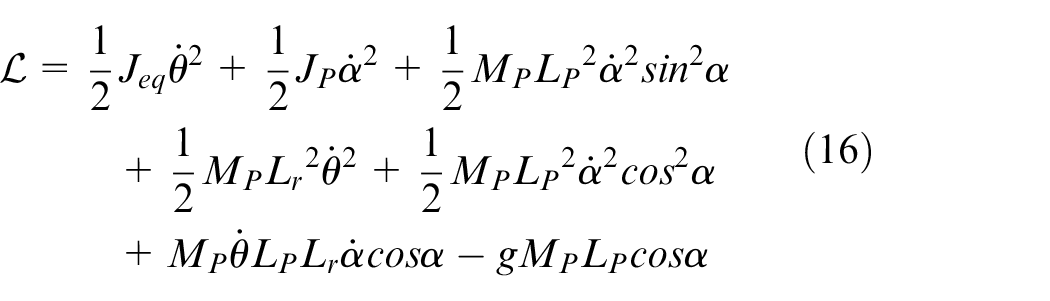
After computing the velocity components along with the x and y coordinates, the Lagrange function of the inverted pendulum is written. In dynamics, Lagrange function

The equations of motion of RIP can be obtained by substituting the Lagrange function


To formulate the Lagrange function, the kinetic and potential energies of the RIP are calculated. The energy due to gravity is defined as the potential energy of the system therefore, for the given system it can be written as:

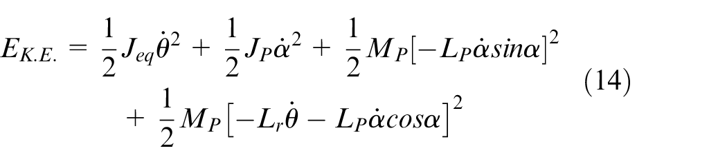
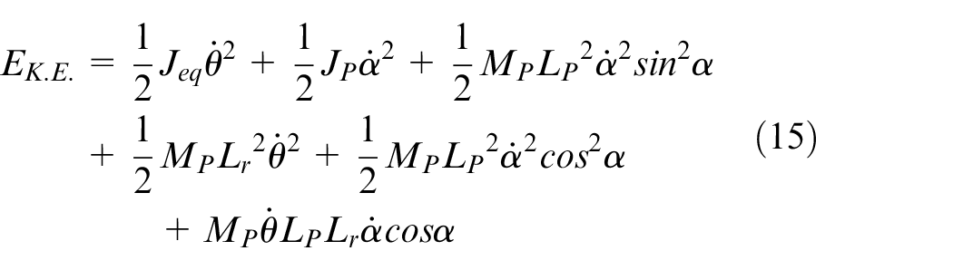
The energy due to the motion of the body is defined as the potential energy of the system. For RIP, the total kinetic energy of the system is equal to the sum of kinetic energies of all of its moving parts as:

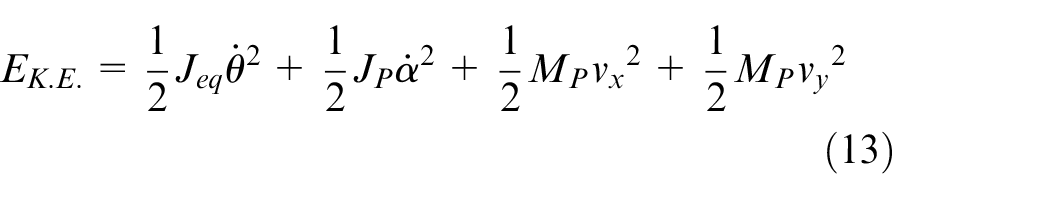
Substituting the values of
Substituting the values of
Torque produced by DC motor is defined by:

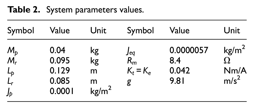
Table 2 presents the values of the system parameters used in the modeling of the RIP.
System parameters values.
To find the state-space model of an inverted pendulum, substituting the (16) and (17) into (9) and (10) and linearizing the nonlinear equations of motion with small perturbations in angles
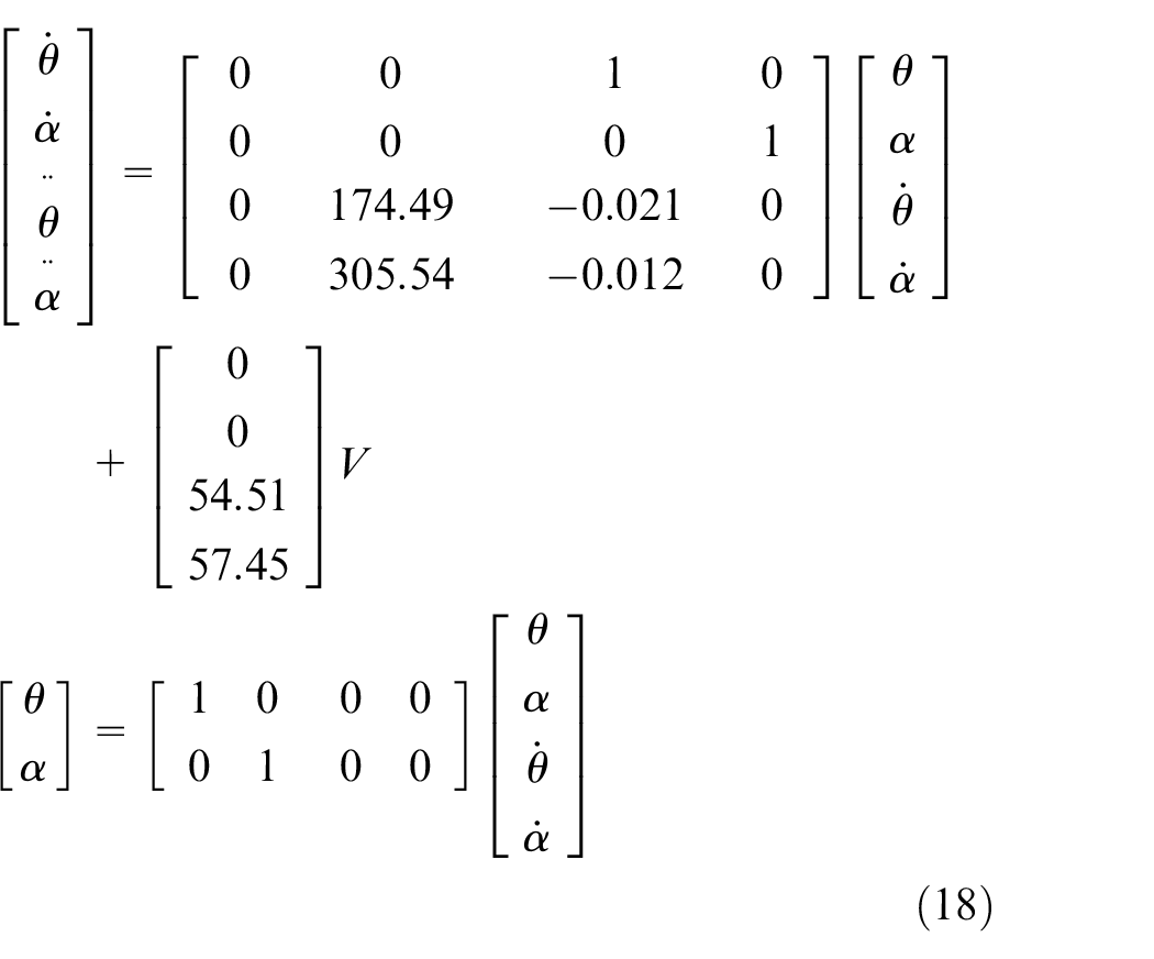
The equation (18) shows the state-space model of the linearized RIP system in which the A, B, C, D matrices of the state-space model are as follows:


Open loop analysis
The characteristic equation of the RIP found from its state-space model is given as:

The equation has been obtained by using the technique mentioned in Chen
3
to find the eigenvalues

The eigenvalues
Controllability analysis
To design a state feedback controller, the given system should be controllable. The system is controllable if the rank of the controllability matrix is equal to the order of the system. The controllability matrix for the given RIP system is outlined as:
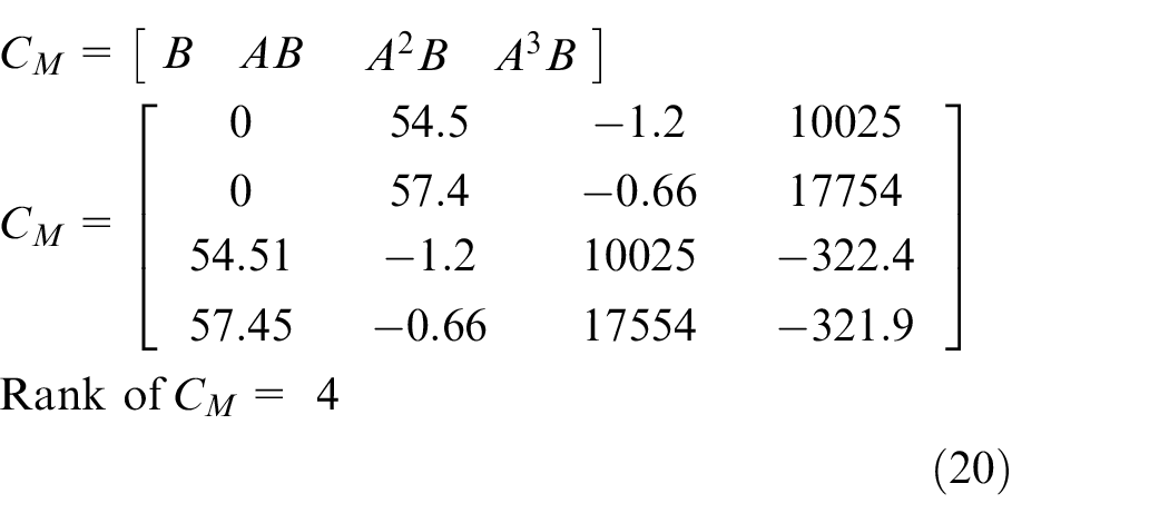
The Controllability Theorem in Chen
3
states that the system is fully controllable if the rank of the controllability matrix
Since the rank of the controllability matrix is full, that is, equal to the order of the system, the given system is controllable.
Design of energy balance, LQR, and FL controllers
Energy balance controller (EBC) design
The EBC is designed to implement the swing-up control of the rotary inverted pendulum. It provides energy to the inverted pendulum to drive it toward its vertical upward reference position by producing the vibrations in the DC motor arm. From Figure 2, the following nonlinear equation of the motion can be written:

The total energy of the pendulum as the function of angle

Differentiating equation (22) concerning angle

The acceleration of the pivot of the RIP is directly proportional to the current responsible for driving the arm of the DC motor, and the current flowing through the armature of the DC motor is directly proportional to the voltage applied to the motor. So using this proportionality, the following nonlinear equation for the EBC can be written:

Where

Where
Linear quadratic controller (LQR) design
The LQR controller is designed to stabilize the RIP at its vertical up position and also to set the DC motor arm at the commanded angular position. LQR is an optimal state feedback controller that calculates its state feedback gains by minimizing the error between the desired and actual states to zero according to the weights assigned to different states and inputs. The cost function minimized by the LQR controller is given as:

Where error

Where the optimal state feedback LQR gain vector is calculated as:

In (30), the matrix P is the solution of the Algebraic Riccati Equation (ARE) defined below:

For the given RIP the weighting matrix of states Q and inputs R are chosen as:
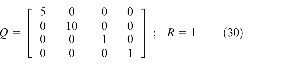
The values of the weighting matrix of states Q are chosen such that the control effort should be made 10 and 5 times in controlling the state variables

Design of fuzzy logic controller (FLC)
Like the LQR controller, the objective of the FLC controller is to stabilize the RIP around its vertical reference position as well as to control the DC motor arm at the commanded angular position. During the last few decades, fuzzy control has evolved as an emerging and productive control technique particularly when it is difficult to control complex systems due to a lack of quantitative information about the system using the conventional control methods. The fuzzy logic control is a special class of intelligent control based on the human behavior of thinking.
In fuzzy control, the numerical values are converted into the linguistic variables (fuzzification), and then IF ELSE rules are applied to these linguistic variables with a predefined set of rules (decision making), and then these linguistic variables are again converted to the numerical numbers (defuzzification). The general structure of the fuzzy logic control system is shown in Figure 3.
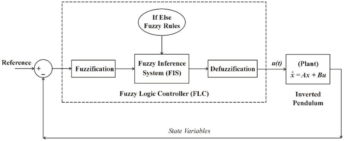
Structure of the FLC controller.
The output variables are the state feedback gains like the LQR controller. More precisely they can be called “fuzzy state feedback gains,” because they are dynamic, unlike the LQR gains. For the LQR controller, the state feedback gains are calculated using the LQR control theory but now these fuzzy state feedback gains are calculated using the fuzzy logic approach to minimize the absolute error between the desired and actual state variables of the system, that is

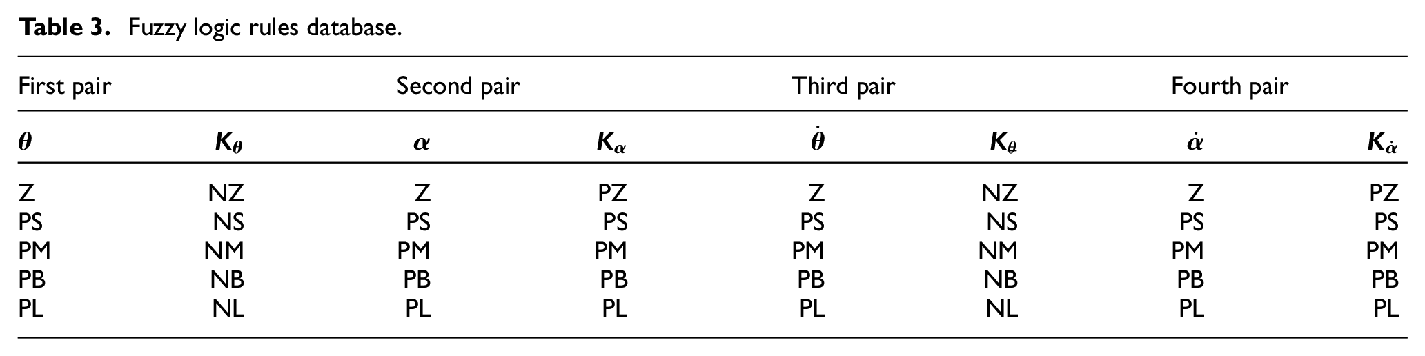
The fuzzy logic rules satisfying (32) for input and output membership functions used in Figures 4 and 5 are presented in Table 3.
Fuzzy logic rules database.
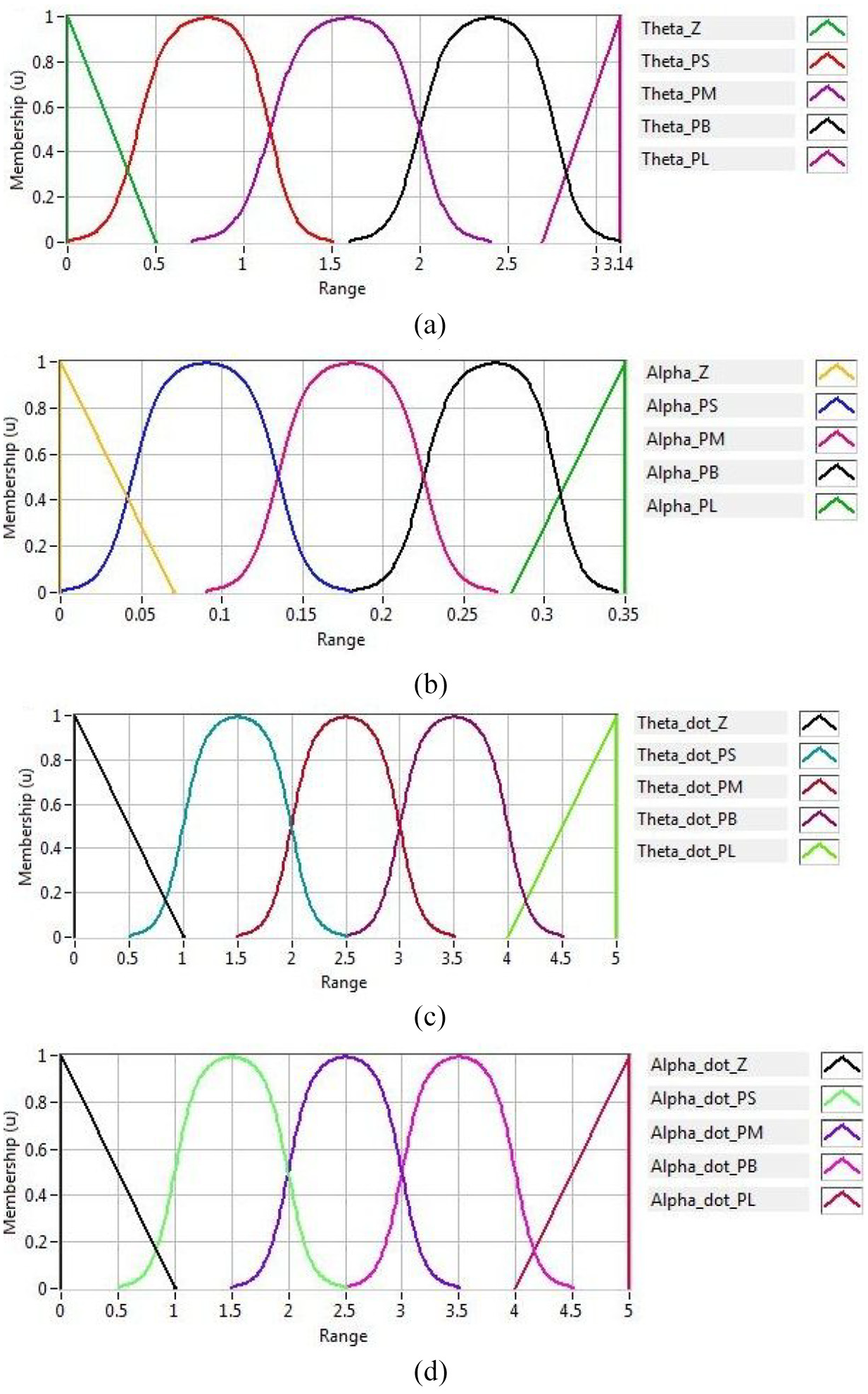
Input variables membership functions.
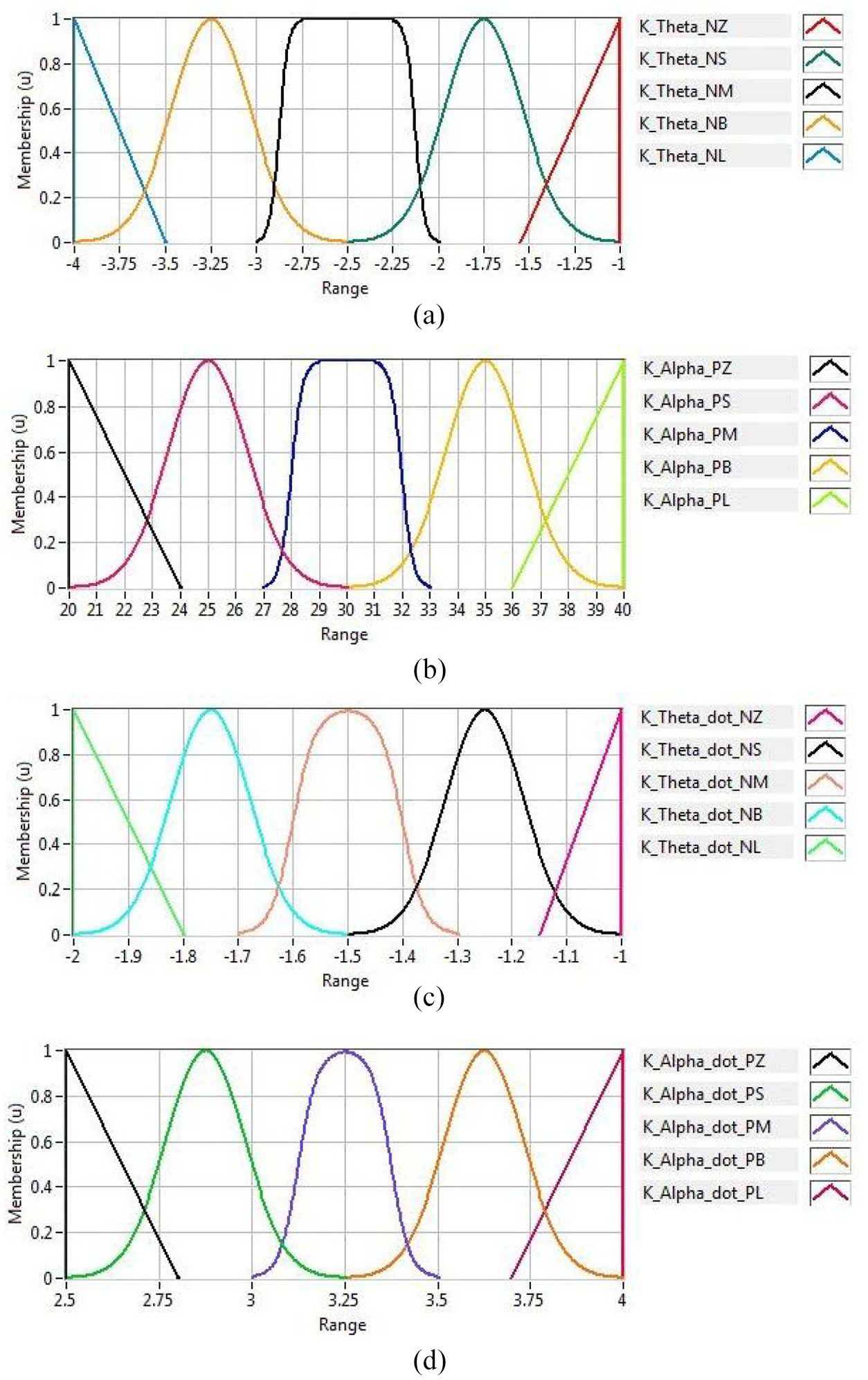
Output variables membership functions.
The abbreviations used in the definition of the membership functions of input and output variables are defined as: Z=Zero, PS=Positive Small, PM= Positive Medium, PB=Positive Big, PL=Positive Large, NZ=Negative Zero, NS = Negative Small, NM=Negative Medium, NB = Negative Big, NL = Negative Large. The fuzzy logic rules are presented in the pair forms in Table 3. For example, the first rule says that, if the value of the angle
The input/output variables and their membership functions designed for a given system are presented in figures 4 and 5.. All the state variables (
The absolute values of the input variables are taken, that’s why all the input variables are starting with the minimum value zero. All the input variables have the same shape membership functions while the range of each of the input variables is different. The ranges of the input variables are found experimentally. The triangular membership functions are used at the extreme values of all of the input variables, to limit the variable within the specified range. While the sigmoid membership functions are used in between the triangular membership functions to have the continuous and smooth variations of the input variables.
During the closed-loop operation, the system must be stable under all conditions. The dynamics of the system should be controlled under the umbrella of the stability of the system. It can be verified from the close loop transfer function of the system with fuzzy state feedback controller that to ensure the stability of the complete close loop system, the values of the fuzzy gains of
Under the abovementioned conditions, all eigenvalues of the close loop system go into the left half-plane, which guarantees the system stability under close loop operation. Considering, the above-stated condition on the fuzzy gains, the output variables for the fuzzy state feedback gains and their membership functions are defined in Figure 5.
Like the input variables, all the output variables of the fuzzy state feedback gains have the same shape membership functions but the range of each of the output variables is different. The range of each of the output variable fuzzy gain is found experimentally. The sigmoid membership functions with a wide flat top are used in the center of the output fuzzy gains to avoid the fluctuations in the values of the fuzzy gains in steady-state operation. At the edges, triangular functions with sharp edges are used to limit the gains within the permissible range. In between the sigmoid and triangular membership functions, Gaussian membership functions are used to have smooth variations in the output fuzzy gains.
Proposed hybrid control scheme (HCS)
To swing up the RIP, Figure 6 depicts the block diagram of the proposed hybrid control scheme using EBC, LQR, and FLC controllers. The RIP is swung up and stabilized to its vertical reference position. In this proposed scheme, EBC is used to implement the swing-up control, while the stabilization control is executed either using LQR or FLC controllers. The EBC is the nonlinear controller used to provide sufficient energy to the RIP to drive it to the vertical upward reference position within ±20° from any non-reference position.
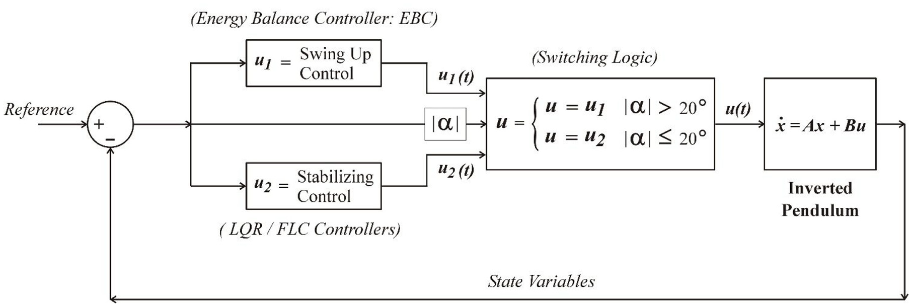
Block diagram for proposed Hybrid Control Scheme (HCS).
The threshold value of the angle
Results and discussion
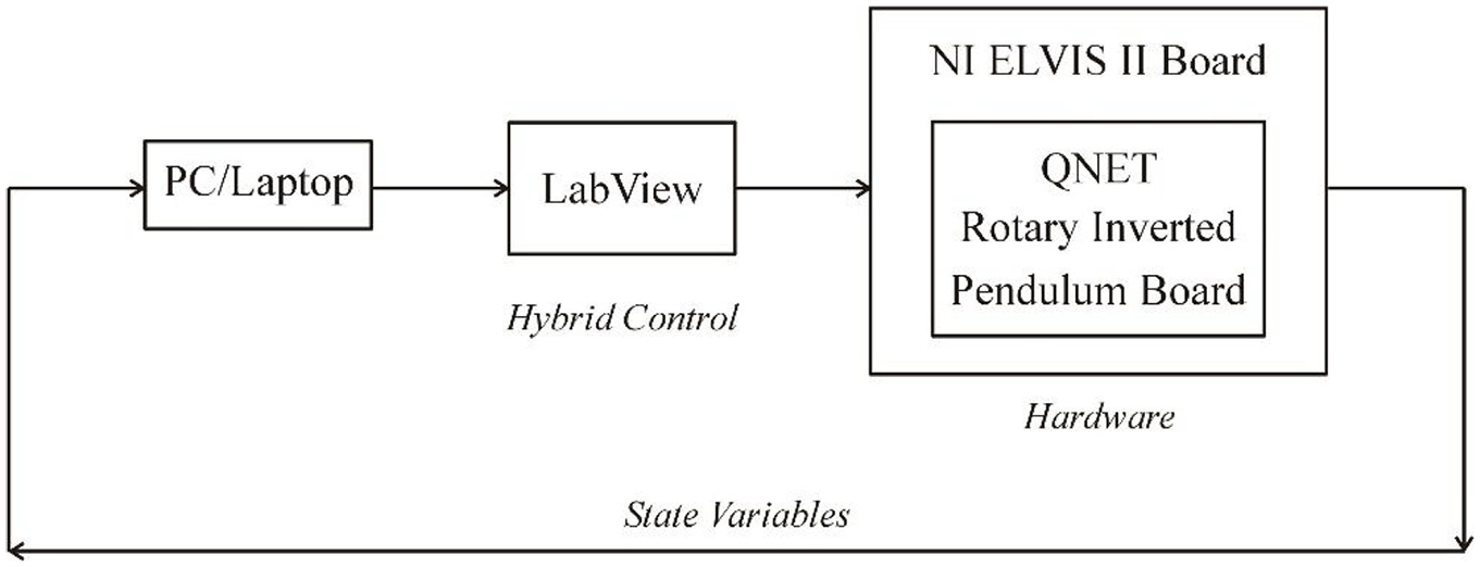
Figure 7 presents the experimental setup used to test the designed control algorithms. In this experimental setup, the RIP board of the QNET RIP board is interfaced with the NI ELVIS II board and the NI ELVIS II board is interfaced with PC/Laptop using the USB connection.
Experimental arrangement.
The hardware board of the QNET RIP board is controlled by using the hybrid control implemented in LabVIEW. LabVIEW has built-in functions to read data from the QNET board and to write the data to the QNET board using the NI ELVISS II board.
Figure 8 shows the practical setup used to obtain the experimental results. The readings of angles
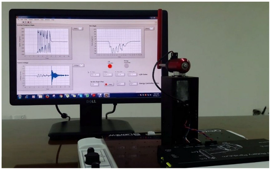
Practical setup.
Experimental results of HCS using EBC and LQR controllers
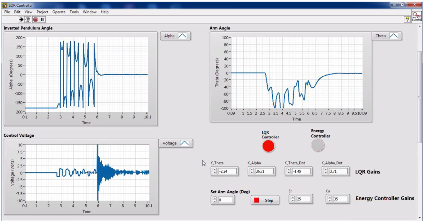
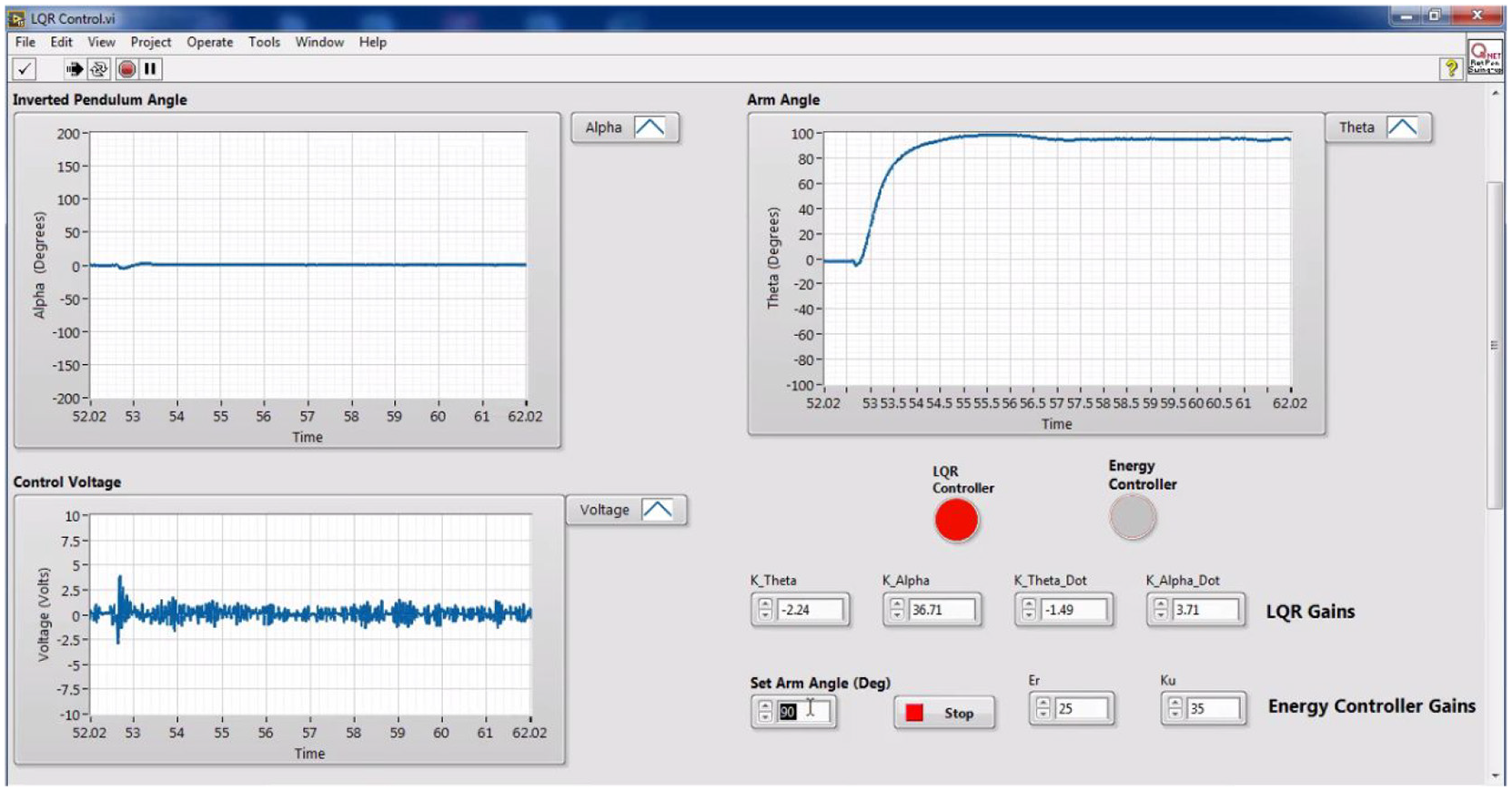
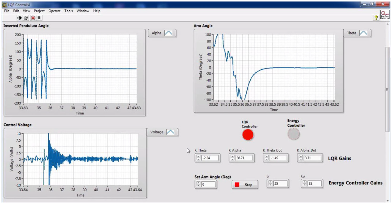
In the section, the experimental results obtained from the proposed HCS using EBC and LQR controller are plotted in Figures 9 to 11. Under three different conditions, that is, for (i)
Tracking performance for
Tracking performance for
Tracking performance for
Figure 9 shows the results for
Figure 10 shows the results for
Figure 11 shows the results for
It is clear from Figures 9 to 11, initially, the EBC controller is applied on RIP and it swung up the RIP approximately within 3 s. Once the RIP is in its swing-up position, the controller is switched from EBC to the LQR, and LQR stabilizes the RIP around its vertical reference, that is,
Under the action of external impulse disturbance force, it is observed that if the magnitude of the impulse disturbance force is small, RIP completely rejects this disturbance force and maintains its reference position of
Experimental results of HCS using EBC and FLC controllers
In this section, the experimental results obtained from the proposed scheme using EBC and FLC controllers for the same conditions as that of the LQR control-based scheme are presented in Figures 12 to 14. The working of the EBC is the same as that is already explained in the first part. When the RIP is a swing-up by the EBC controller and
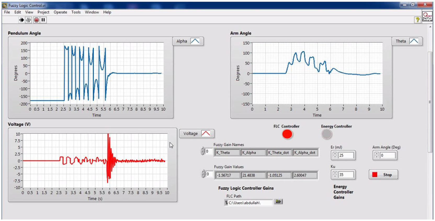
Tracking performance for
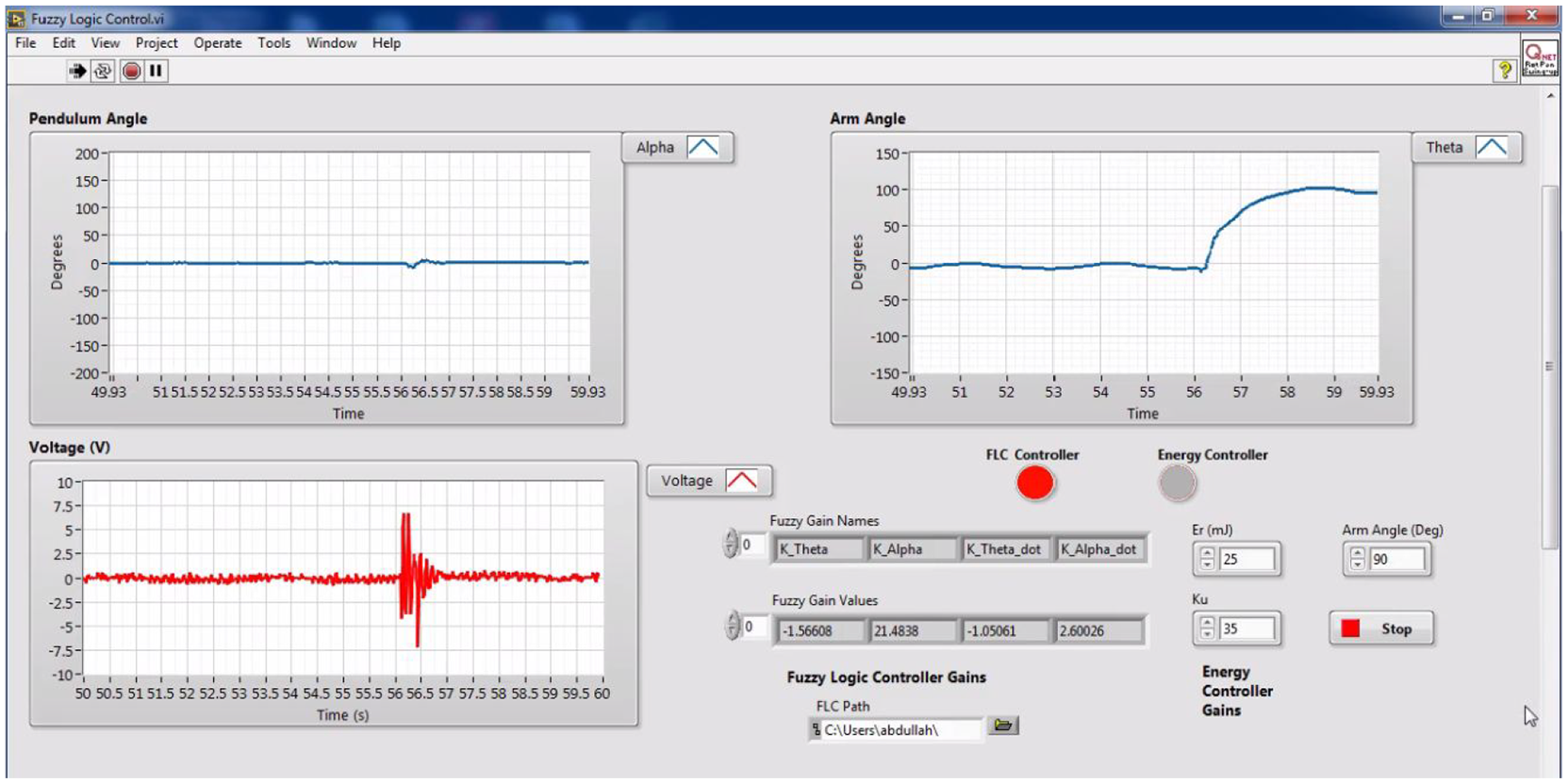
Tracking performance for
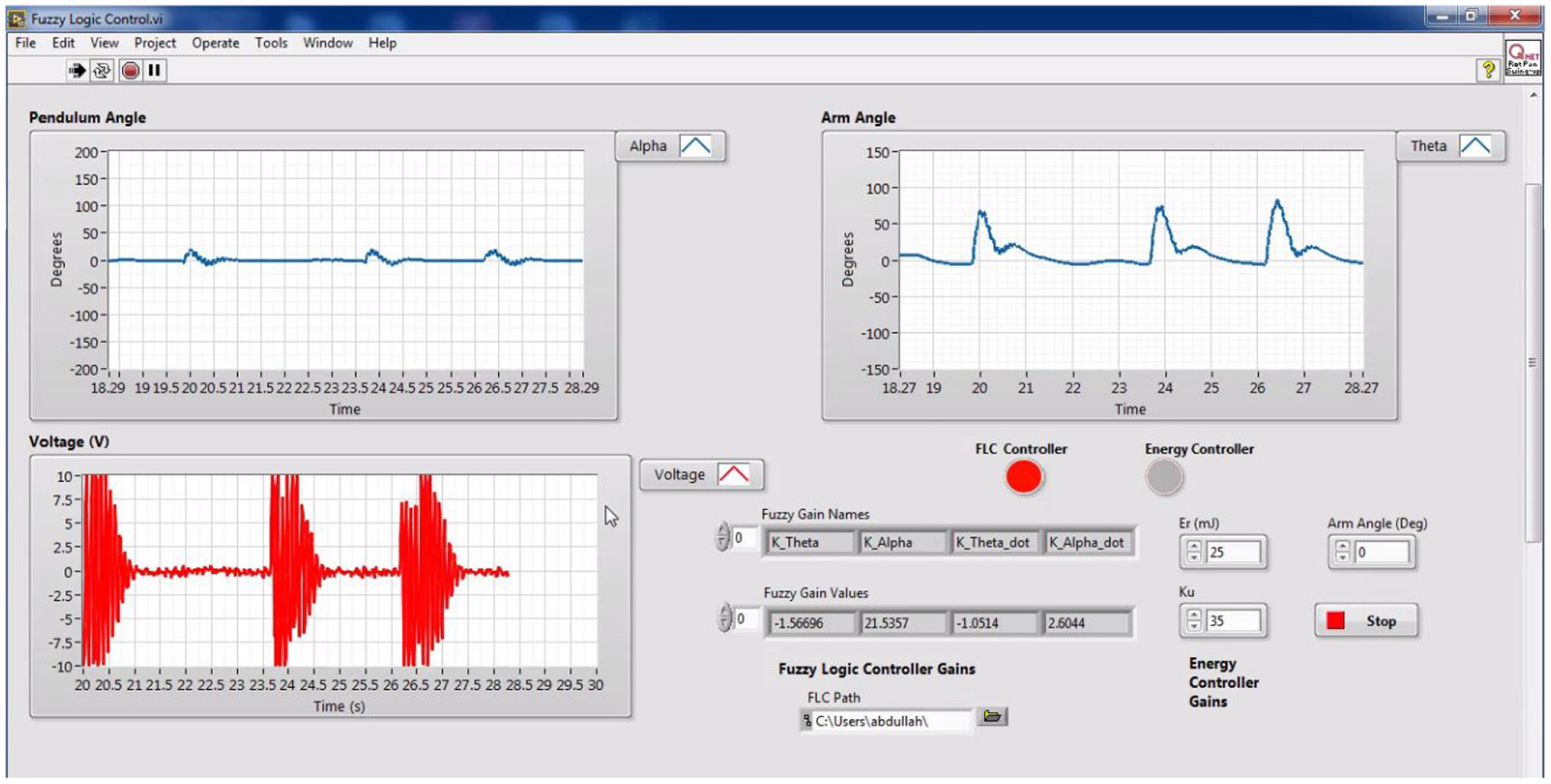
Tracking performance for
Figure 12 shows the results for
Figure 13 shows the results for
Figure 14 shows the results for
From Figures 12 to 14, it is evident that the FLC controller can stabilize the RIP around its reference position approximately within 0.3 s. The angle
When the RIP is operating at its reference position the magnitude of the control voltage is also very stable and less than 0.5 V. When impulse disturbance of increasing magnitude is applied to the RIP, it maintains its vertical reference position by nullifying the effect of the impulse disturbance forces. The steady value of the angle
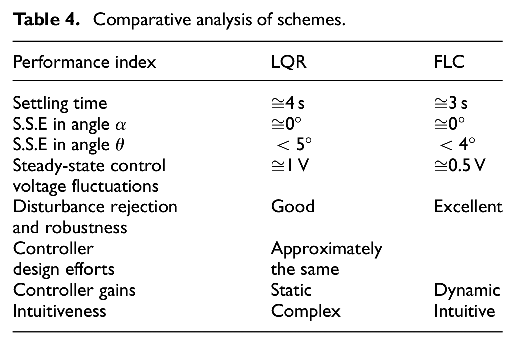
Comparative analysis of schemes.
The comparison of the proposed technique with the existing technique 29 is carried out for various important parameters as summarized in Table 5.
Comparison with existing technique.
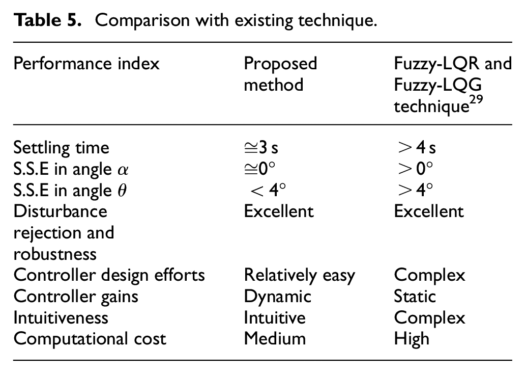
The main advantage of the proposed hybrid control scheme for RIP, as evident from Table 5, is a better transient response with less complexity and low computational cost of the controller.
Conclusions
In this study, a hybrid control scheme was presented to implement the swing up and stabilization control of rotary inverted pendulum based on energy balance and FL controllers respectively. The energy balance controller was implemented for the swing-up control by providing the required amount of energy to the pendulum arm to drive it from any non-reference position to its vertical up reference position. Once the inverted pendulum stick was within the range of threshold value of ±20° from the vertical up reference position, the switching logic was executed and the control was switched over to the stabilizing FLC. The FLC not only stabilized the inverted pendulum stick at its vertical up reference position but also set the pendulum arm at the commanded angular position. FLC automatically tunes the values of the fuzzy state feedback gains in real-time to minimize the absolute error between the desired and actual states of RIP by applying the FL rules. The proposed hybrid control scheme was experimentally tested on the QNET RIP board provided by the National Instruments. By comparison of experimental results, it was concluded that the proposed fuzzy logic-based hybrid control scheme gives the optimal control performance in terms of achieving satisfactory transient, steady-state, and robust responses from a given RIP system, as compared to the conventional LQR based control scheme. The proposed control scheme is also relatively less complex with a low computational cost and the desired response characteristics as compared to the existing ones in the literature.
In the future, this work can be expanded either by evaluating the performance of the proposed hybrid control scheme against many other standard control techniques with simulation works as well such as fuzzy-neural networks, machine learning methods, adaptive control methods, and sliding mode control methods or by investigating the new hybrid control schemes giving even more optimal and robust control performance with fewer overshoots/undershoots. The robustness of the controller against the parameter uncertainty such as the mass of the pendulum may also be considered.
Footnotes
Acknowledgements
The authors would like to thank colleagues for suggestions to improve the paper quality.
Declaration of conflicting interests
The author(s) declared no potential conflicts of interest with respect to the research, authorship, and/or publication of this article.
Funding
The author(s) received no financial support for the research, authorship, and/or publication of this article.