
Abstract
Mass measurement using relay feedback of velocity and restoring force compensation is investigated for determining the mass of an object under weightless conditions. In the measurement system, the velocity of the object is fed back through a relay with hysteresis and the force acting on the object is switched from a positive value to a negative value when the velocity reaches a positive threshold and vice versa. As a result, a limit cycle is induced in the measurement system and the mass is estimated based on the period of the limit cycle. In addition, restoring force compensation with a spring is introduced to avoid the drift of the trajectory. This compensation makes the static equilibrium state unique. However, the trajectory still drifts slightly. It causes some error in measurement when a simple formula of estimating mass is applied. To eliminate such an error, a new formula is derived to estimate the mass independently of the position of the trajectory that is determined by the switching positions in the relay actions. When the switching positions deflect from the origin at which the spring is in the natural length, the trajectory is not at the center and becomes asymmetric. It is analytically shown that the period of the limit cycle is minimum when the switching positions are at the origin. It indicates that mass is overestimated with the simple estimation formula when the trajectory is not at the center. The validity of the modified formula and the analytical results are confirmed experimentally.
Introduction
The determination of the mass of an object is one of the oldest measurement techniques.1,2 At the very early stages of trade, it was necessary to find out the mass of an object. Now, the space age will just enter a new stage. 3 Various exciting projects have been proposed by venture companies. In several projects such as the production of novel medicines in space, mass measurement in such a special environment will be necessary.
For mass measurement on earth, scales and balances have been used since the ancient past. 1 However, they do not work without gravity on earth. To measure mass under no-gravity conditions, therefore, other approaches are required. A variety of methods have already been proposed.4,5 They are categorized into
Estimate from the natural frequency of spring-mass system.6,7
Use the frequency-controlled method. 8
Use the dynamic measurement method. 9
Estimate from the centrifugal force of a rotating object. 10
Operate a dynamic vibration absorber as a measurement device.
Estimate based on the law of conservation of momentum.
Estimate from the period of limit cycle induced in relay feedback system.
This paper focuses on the seventh category mainly because the principle of measurement and the required hardware are rather simple.
Relay feedback has been studied intensively for more than a century. 18 It has been applied in various control systems such as auto-tuning of process controllers,19,20 current controllers, 21 servomechanism. 22 It is also useful in system identification23,24 and parameter identification such as process model parameters in under-damped second order plus dead time processes, 25 indoor temperature lag in variable air volume systems 26 and backlash in two-mass systems. 27 We have applied it to mass measurement. 28 One of the reasons of this application is an expectation of robustness to disturbance as explained in the following. A limit cycle is peculiar to nonlinear systems. It often appears when some gain exceeds a critical value and should be avoided in designing or tuning the controller. It tends to be rather persistent so that it is not easy to remove it once it appears in the target system. In another aspect, it is rather robust against parameter variations and disturbance. Such properties are appropriate for measurement. Thus, this category has been studied intensively.29–32
Measurement systems belonging to this category are classified into two types according to the quantity to be fed back. 28 In one of them, the velocity of the object is fed back through an on-off relay with hysteresis. 16 The other feeds back the displacement through an on-off relay with dead zone. 17 The advantage of the former over the latter is the simpler logic of relay feedback. Two on-states appear in the former while three states consisting of two on-states and one off-state appear in the latter. It indicates that period or frequency measurement can be easier in the former. For this reason, the former is treated in this article.
One of the problems of the original target system was that the object drifted during measurement because the velocity of the object was solely fed back and there was no restoring force. 29 It causes some difficulty in achieving stable measurement. To prevent such drift, a spring was installed to generate restoring force. 16 However, the steady-state motion (trajectory) is not determined uniquely although the static equilibrium state is made unique by this element. As a result, it tends to drift slightly, which causes some error in measurement when the original formula of determining the mass is applied. To eliminate such an error, a new formula has been proposed to consider the non-uniqueness of the steady-state motion. 30 In this article, the measurement system is further studied both analytically and experimentally. The contributions can be summarized as follows:
The derivation of the modification is described at full length.
It is analytically shown that the periods of the two states are different when the switching position deflects from the origin at which the spring is in the natural length.
It is also analytically shown that the period of the limit cycle is minimum when the switching positions are at the origin.
The validity of the modified formula and the analytical results are confirmed experimentally.
The remainder of this article is organized as follows. Section II presents the original formula of estimating mass. A new formula considering restoring force is derived in Section III where the characteristics of the measurement system are also analyzed. Section IV describes an experimental apparatus and experimental results that support the analytical predictions. Section V concludes this article.
Principle of measurement without restoring force
System configuration
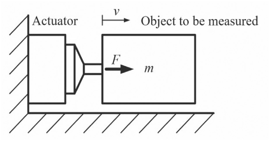
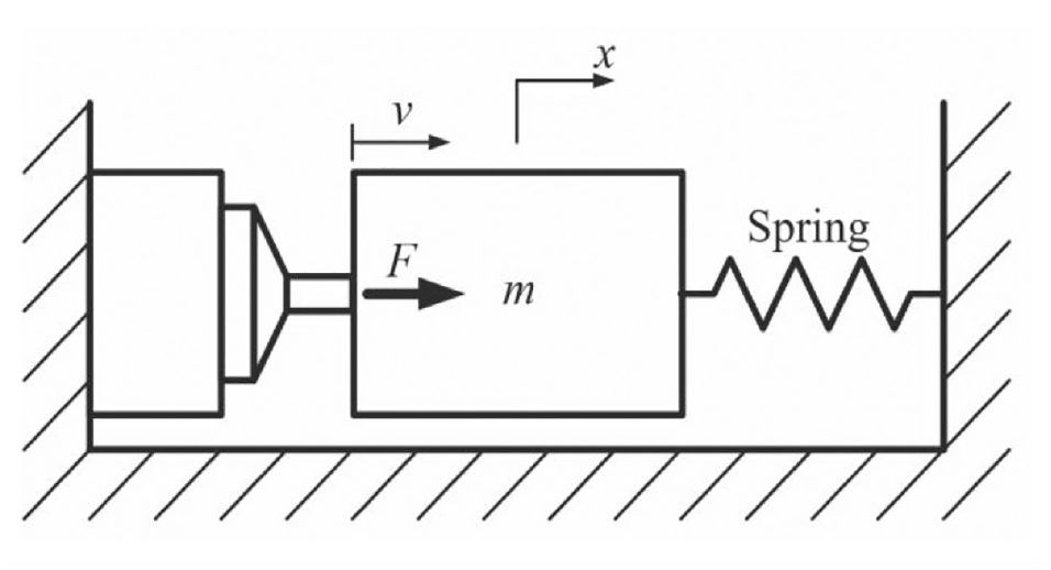
Figure 1 shows a physical model of the proposed mass measurement system. 16 It is made up of four elements:
Actuator that drives an object to be measured,
Sensor that detects the velocity of the object,
Controller that produces switching signals from the sensor signal,
Amplifier that energizes the actuator.
Figure 2 shows a block diagram of the measurement system from a viewpoint of control. Its operation is explained by Figure 3. The force F(t) acting on the object is generated by the actuator. It is switched when the velocity v of the object reaches the threshold values. When a positive force
Basic model of mass measurement system.
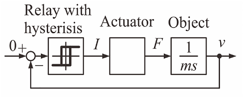
Block diagram of relay feedback system.
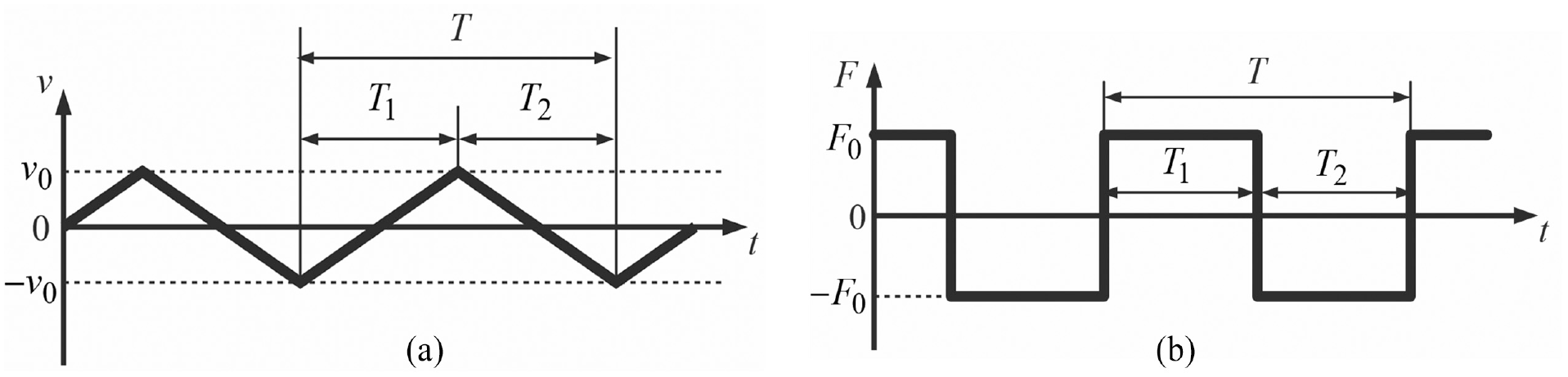
Operation of measurement system: (a) velocity of the object and (b) force acting on the object.
Estimation formula
There are two states. In one of them, the force acting on the object is
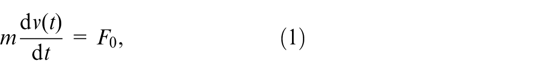
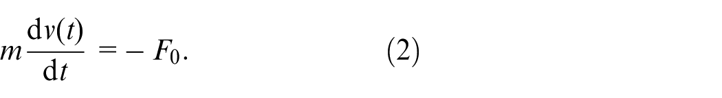
Solving equation (1) with

where
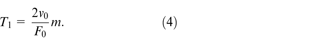
The period during which
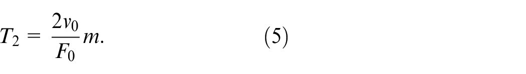
Apparently,

The period of the limit cycle T is expressed as
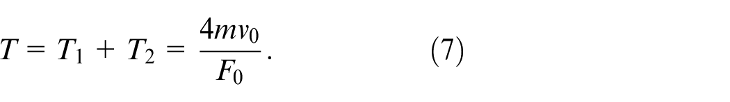
From equation (7), the mass is given by
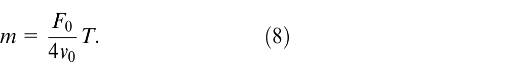
Equation (8) indicates that the mass of the object is estimated from the period of the limit cycle T.
Problem of original method
In the original measurement system described in the previous sections, the velocity of the object is solely fed back and there is no restoring force. Therefore, the drift of the trajectory is unavoidable in the actual operation. 29 It is to be noted that drifting limit cycle is positively used in the backlash identification. 27
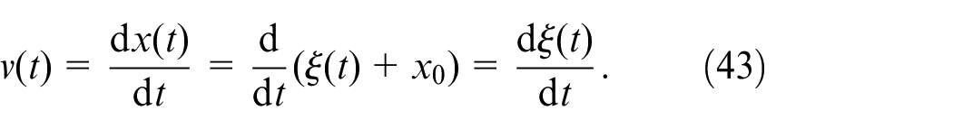
Principle of measurement with restoring force
System configuration
A spring was inserted between the object and the base to avoid the drift as shown by Figure 4. 30 Figure 5 shows a block diagram of the modified measurement system. In this configuration, the static equilibrium position of the object is determined uniquely from the natural length of the spring. The formula estimating the mass in this system will be derived in the next section.
Basic model of measurement system with a spring.
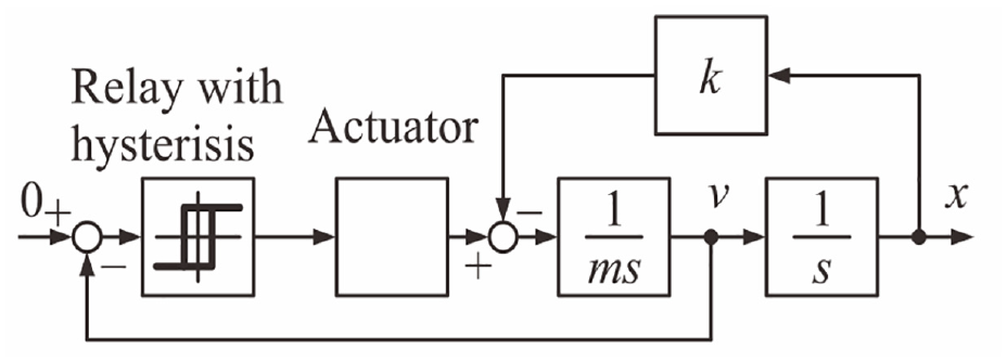
Block diagram of relay feedback system with restoring force compensation.
Estimation formula
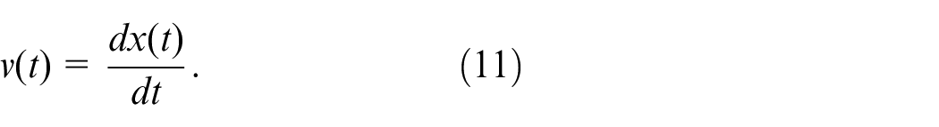
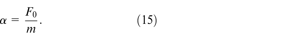
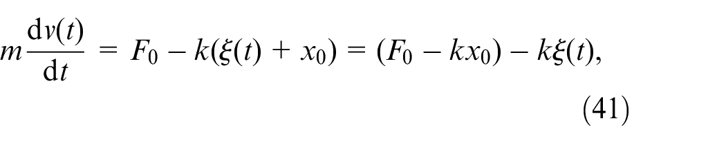
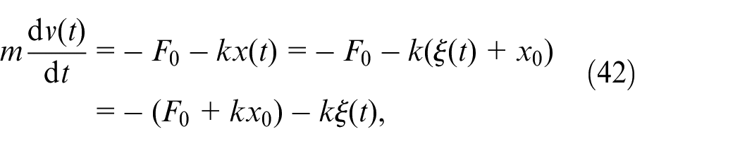
The equation of motion in each state becomes
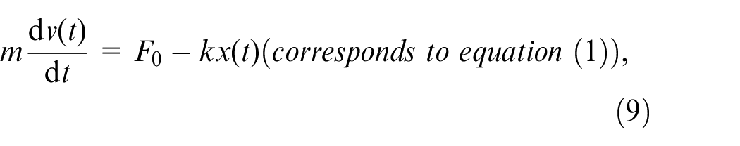
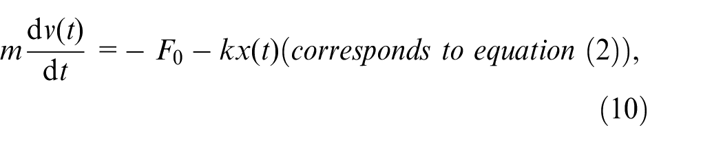
where
To solve equation (9) with
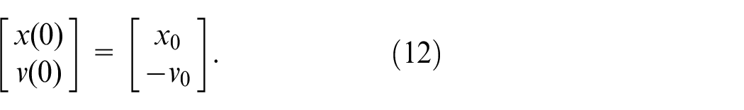
The solution for these initial conditions is given by
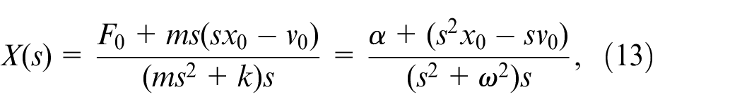
where
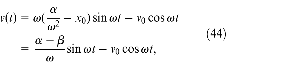
The inverse Laplace transformation of equation (13) is
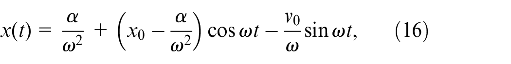
Differentiating equation (16) gives
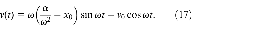
The next switching occurs when the velocity reaches the upper threshold, that is,
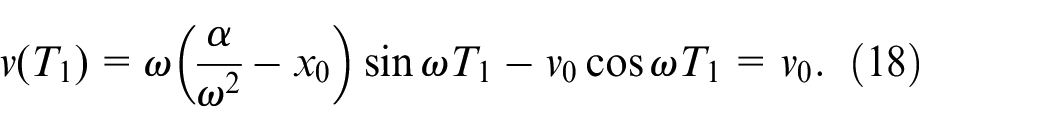
From equation (18), we derive
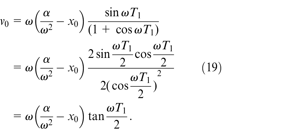
Therefore,
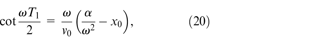
or
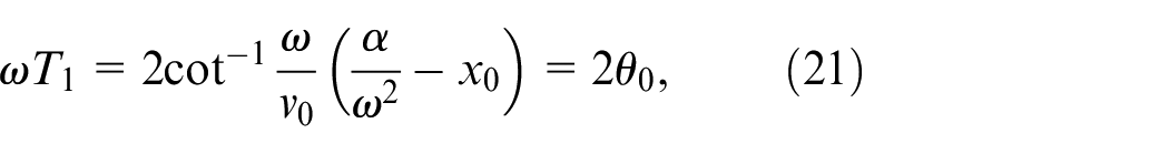
where
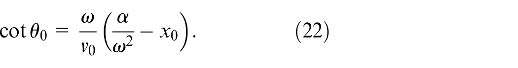
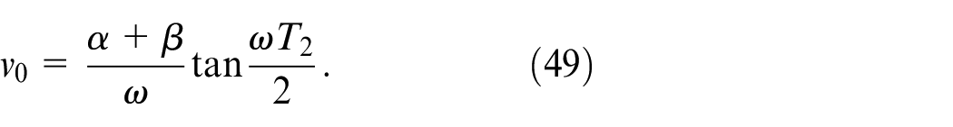
The position of the switching is given by
Therefore, at the switching time of
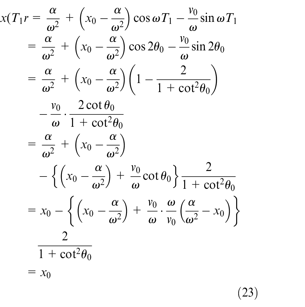
Comparing equation (12) with equation (24), we find that the force is switched at the same position
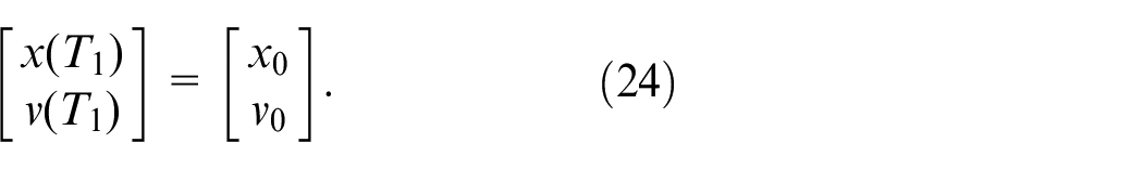
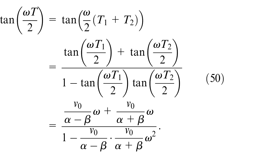
The period
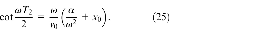
Combining equation (20) with equation (25) gives
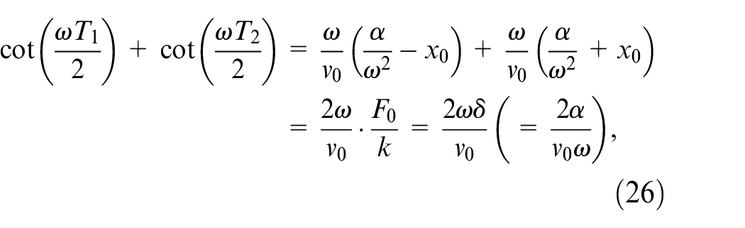
where
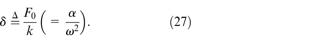
From equation (26), we get
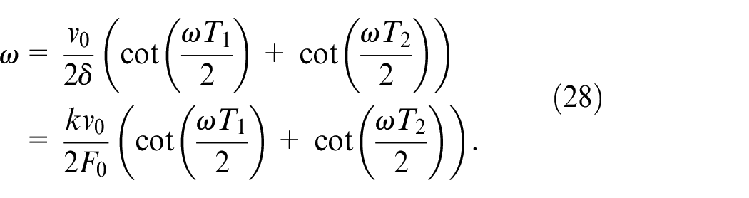
Equation (28) does not contain the switching position
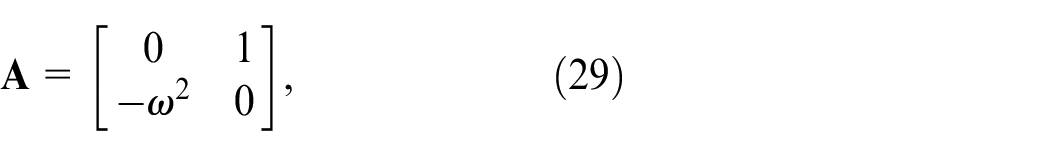
and its eigenvalues are
In spite of drifting, the mass can be determined independently from the switching position according to equation (28) as follows
Identify
Measure
Solve equation (28)numerically and find the value of
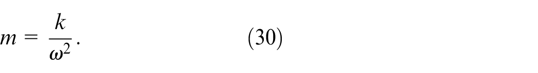
Calculate m from equation (14), that is,
Analysis on switching position
From equations (20) and (25), we can derive the following equation:
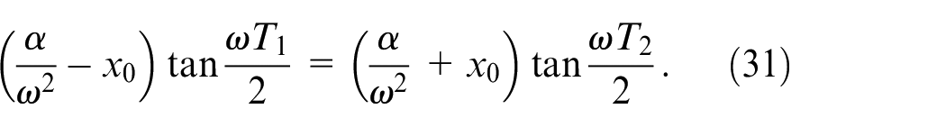
From equation (31), we get
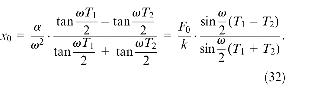
Equation (32) indicates that when the spring is sufficiently soft to satisfy

the switching point corresponds to the static force balancing point 28
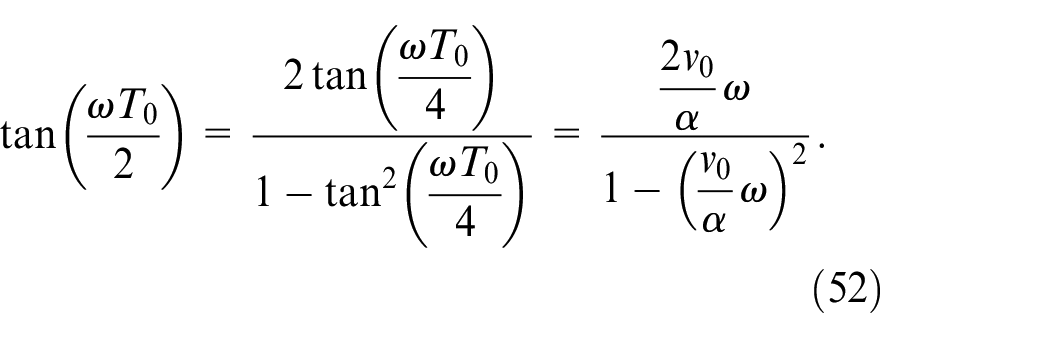
Equation (32) also indicates that the switching position is zero, that is,
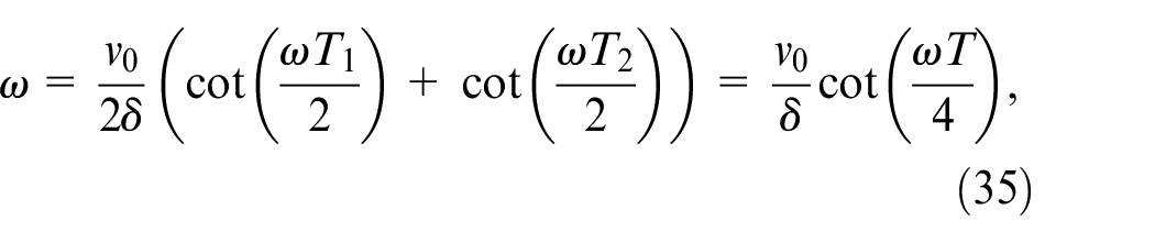
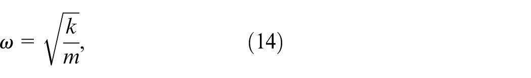
where
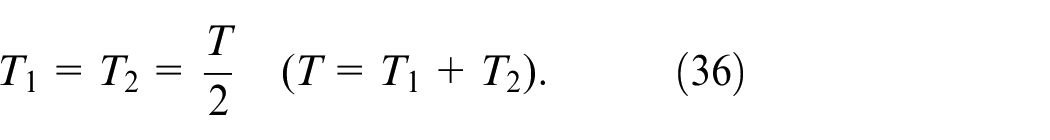
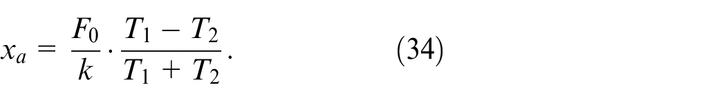
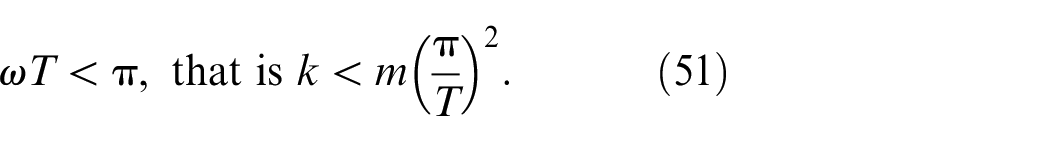
From equation (35), we get
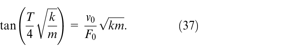
Equation (37) has been derived under the assumption of
Relation between limit cycle periods and switching position
It will be shown that the period of limit cycle

∵ (equations (20) and (25))
A new variable
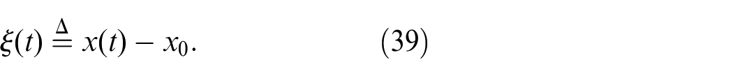
It is noted that the switching positions in the steady limit cycle should satisfy

Equations (9) and (10) are rewritten with this variable as
where
Equation (17) becomes
where
It is apparent from equations (15) and (45) that
The next switching occurs when the velocity reaches the upper threshold, that is,
From equation (47), we get
Similarly,
From equations (48) and (49),
It is assumed that the spring is sufficiently soft to satisfy
The following equation is derived similarly in deriving equation (50).
Compare
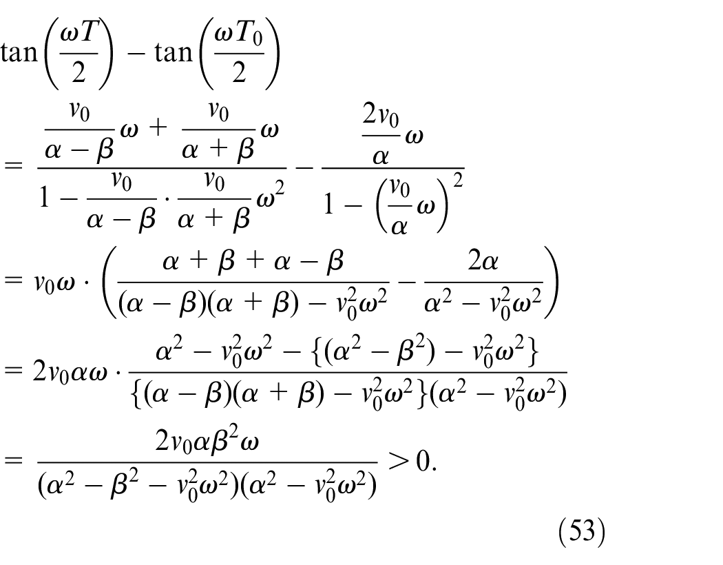
In the range of

Equation (54) indicates that the period of limit cycle
This result indicates that the mass is overestimated when the difference of the periods is neglected and the mass is estimated from the value of T solely because the period increases as the mass increases. This prediction is supported by a numerical analysis result shown by Figure 6. In this analysis,

which correspond to the conditions of the experiment described in Section 4. The value of mass is assumed that

The periods
The estimated mass
Figure 6 demonstrates the validity of the prediction that the estimated mass is larger than the actual mass.
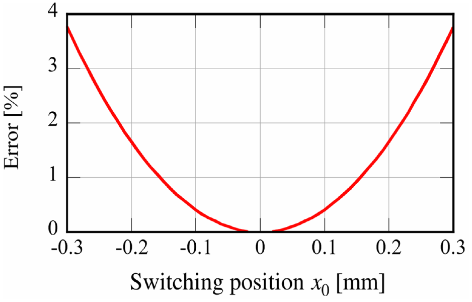
Error of estimation from the total period T.
Experiment
Experimental setup
Figure 7 shows a picture and a schematic drawing of the fabricated experimental apparatus. 29 To avoid the uncertainties due to Coulomb friction and viscous damping, and to restrict the motion to one-degree-of-freedom translation, the moving part is supported by three air bearings. The friction and damping during the reciprocal motion is minimized. Two voice coil motors (VCM’s) are installed in this apparatus. One of them operates just as the actuator in Figure 1, which is denoted by VCM 1. The other denoted by VCM 2 operates as a vertical spring to adjust the stiffness readily. The coil current is controlled in proportion to the displacement of the object; the stiffness is proportional to the feedback gain.
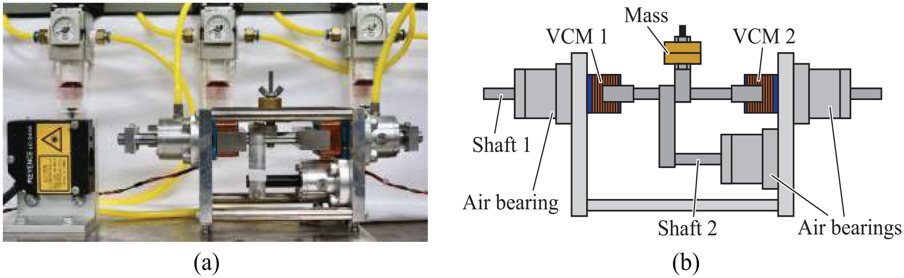
Experimental apparatus: (a) picture and (b) schematic drawing.
To detect the velocity of the object, a laser vibrometer (Polytec OFV-5000) is used to shorten the detection time as much as possible.
29
Its response speed is rather fast; the signal delay is 24 µs (catalog value). To detect the displacement of the object, a laser displacement meter (KEYENCE LC-240) is used. Its signal delay is 100 µs (catalog value). These sensor signals are inputted to a digital controller (dSPACE, DS1103) through A/D converters. In the controller, the binary command signal (
In these ways, the motion control described by equations (9) and (10) has been achieved.
Experimental result
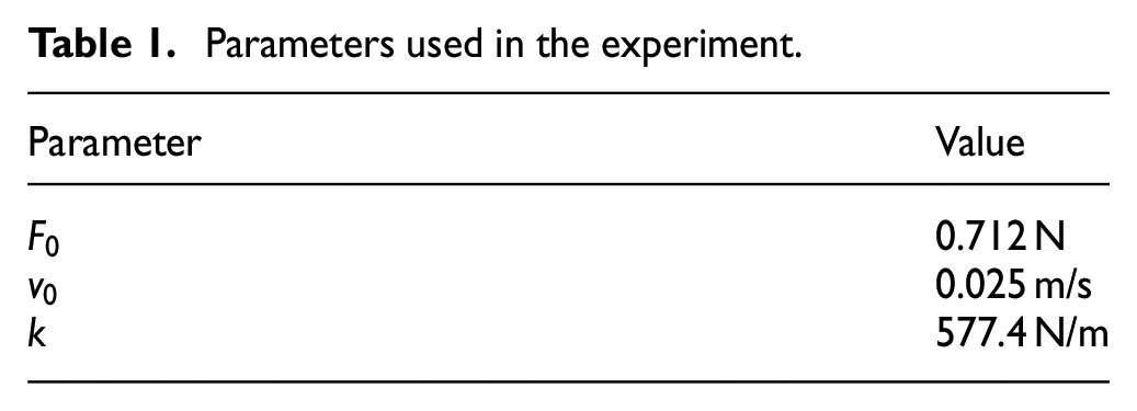
The value of each parameter set in the experiment is presented in Table 1. Figure 8 shows displacement of the measured object whose mass is 586.8 g. It indicates the measurement object drifts slightly. The periods
Parameters used in the experiment.
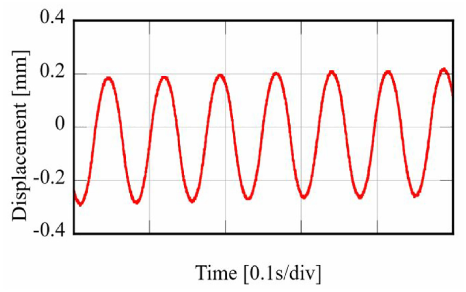
Displacement of the object during measurement; slight drift is observed.
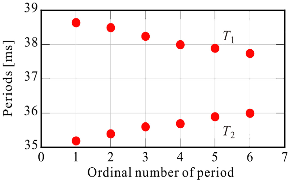
Periods during drift.
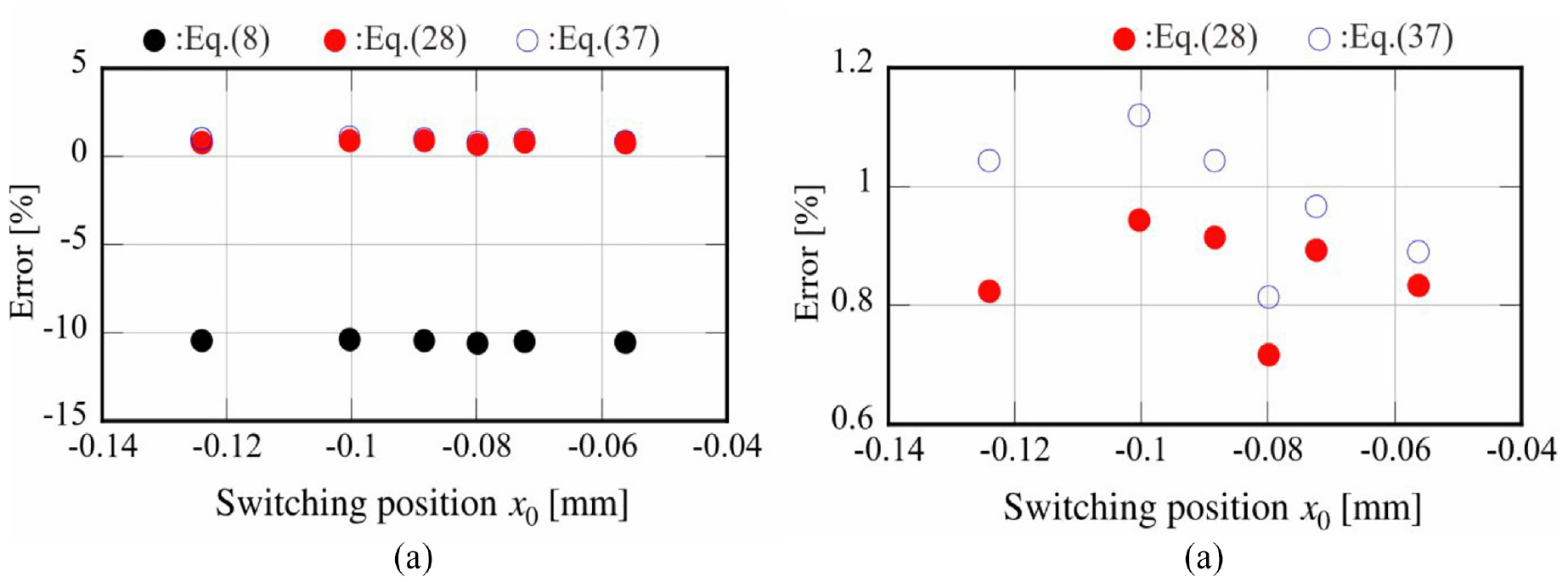
Comparison in error of estimations calculated according to equations (8), (28), and (37): (a) three estimations; the estimations by equation (28) almost overlap those by equation (37) and (b) closed view of the comparison.
Figure 11 shows the estimation according to equation (28) for various masses. The linearity is rather good. The errors are positive as shown by Figure 12. It indicates that the mass is estimated to be larger than the actual mass. Such an overestimation can be caused by the delay of detection of the velocity. In this experiment, however, the laser vibrometer with high-speed response was used for the detection of the velocity so that the effect can be small. Another possibility of this error may be the delay in measuring the periods; a digital oscilloscope was used in these experiments. A new measurement device with higher response has been developed for an improvement in this aspect. 36
Measurement of various masses; estimated values are calculated from equation (28).
Error of estimation.
Conclusions
In the mass measurement system using a relay feedback of velocity, a mass estimation equation was derived precisely from the equations of motion. The derived equation does not include any parameter depending on the switching position. As a result, the mass can be determined independently of the switching position, which enables accurate mass measurement in spite of the drift of the trajectory. Mass measurement experiments were carried out in the developed experimental apparatus. The measurement accuracy was improved by calculating mass according to the derived equation; the measurement error was reduced approximately by one-tenth. There still remained approximately one-percent error. It can be reduced by identifying the parameters more accurately.
Footnotes
Declaration of conflicting interests
The author(s) declared no potential conflicts of interest with respect to the research, authorship, and/or publication of this article.
Funding
The author(s) received no financial support for the research, authorship, and/or publication of this article.