
Abstract
High-speed scanning is a huge challenge to the motion control of step-scanning gene sequencing stage. The stage should achieve high-precision position stability with minimal settling time for each step. The existing step-scanning scheme usually bases on fixed-step motion control, which has limited means to reduce the time cost of approaching the desired position and keeping high-precision position stability. In this work, we focus on shortening the settling time of stepping motion and propose a novel variable step control method to increase the scanning speed of gene sequencing stage. Specifically, the variable step control stabilizes the stage at any position in a steady-state interval rather than the desired position on each step, so that reduces the settling time. The resulting step-length error is compensated in the next acceleration and deceleration process of stepping to avoid the accumulation of errors. We explicitly described the working process of the step-scanning gene sequencer and designed the PID control structure used in the variable step control for the gene sequencing stage. The simulation was performed to check the performance and stability of the variable step control. Under the conditions of the variable step control where the IMA6000 gene sequencer prototype was evaluated extensively. The experimental results show that the real gene sequencer can step 1.54 mm in 50 ms period, and maintain a high-precision stable state less than 30 nm standard deviation in the following 10 ms period. The proposed method performs well on the gene sequencing stage.
Introduction
DNA nanoball (DNB) sequencing technology has been considered as a low-cost, high-efficiency, and promising prospect for gene sequencing. 1 Among the gene sequencing, a large number of DNA nanoballs (DNBs) transformed from DNA fragments are absorbed onto the silicon flow cell with a grid-patterned array. After unchained hybridization and ligation, these DNBs will emit different wave-length fluorescence under the illumination of laser. The fluorescence from each DNB is detected by the specific pixel of the microscopic imaging system to determine the base type. Due to the limited field of view on microscopic imaging system, a high-precision stage is used to carry the silicon flow cell and pass through the microscopic imaging system step by step to achieve traversal scanning of all DNBs on the chip. The motion control performance of the stage is critical for the gene sequencer. The stage must keep high-precision position stability to ensure clear fluorescence detection of the DNBs after stepping a field of view length. Also, the settling time of a single-step motion determines the scanning speed of the DNBs. The less settling time means the faster scanning speed, and the more base data is acquired.
However, achieving high-precision position stability with minimal settling time has always been a challenging problem in the field of motion control.2,3 Many related works may be classified into the following three groups:
Develop the high-precision and high-bandwidth stage. The higher structural bandwidth of the stage means that the larger allowable bandwidth of the control system and the less settling time of stepping motion. A plane motion stage was introduced.4,5 Two sets of motors were arranged on the same plane to realize the plane motion in the X/Y direction, and the rigidity and precision were greatly improved than the laminated structure. A flexible structure X/Y stage was developed. 6 Each axis was composed of a doubly clamped beam and a parallelogram hybrid flexure with compliant beams and circular flexure hinges, and a piezoelectric driving component was used. The stage achieved 8 kHz resonant frequency but only 15 µm stroke. To compensate for the short-stroke shortcomings, the coarse-fine dual structure stage was proposed.7,8 The coarse stage exploited long-stroke and heavy-loading motion mechanism with lower-precision. The fine stage was superimposed on the coarse stage. The short-stroke with higher-precision and better-response drive components was utilized, such as PZT-based or voice coil motors, to further compensate for the residual motion of the coarse stage motion. The dual structure stage can realize long-stroke, high-speed, and high-precision motion trajectory tracking, but the system structure was complicated and costly, and it was not easy to achieve precise synchronization control for the coarse and fine stage.
Optimize the control structure. The composite control method using feedback and feedforward is always effective. Especially when the feedforward controller highly matches with the controlled object, high-speed and high-precision control effects can be achieved. Around this idea, the Jerk derivative feedforward control was proposed, 9 which was further imposed on the acceleration feedforward to compensate for the low-frequency component of the servo error caused by the high-order resonance term. Another Jerk feedforward control with adjustable damping factor was employed to obtain better feedforward performance by adjusting the damping factor for different input trajectories. 10 Considering that the change of model parameters and un-modeled items can lead to a decrease of control performance, a variable gain control method applied on a wafer stage was developed. 11 The variable gain control term was added based on a fixed gain feedback controller, and the data-driven design method with performance-orientation was adopted to find the optimal parameter values for the variable-gain controller. The adaptive sliding mode variable structure control was introduced to achieve high bandwidth control by overcoming the adverse effects of unknown disturbances and nonlinearity friction.12,13
Optimize the input trajectory. For some flexible or low damping coefficient stages, such as the air bearing stage, the residual oscillations caused by the single-step input trajectory will be attenuated for a long time. Some methods of optimizing the input trajectory can greatly reduce the residual oscillation and shorten the settling time of stepping motion. Trajectory filtering was based on the idea of frequency suppression, using a low-pass filter or notch filter to attenuate the trajectory component at the oscillation frequency point. 14 Input shaping was to divide a single-step trajectory into a multiple-step trajectory with specific time delay and step, and a stable response was achieved after the superposition of positive and negative oscillation.15,16 Input shaping can produce high performance in the case of accurate parameter estimation.
Although great progress has been made in the high-precision position motion control, most approaches are based on the premise that the final position of the motion is pre-determined. The control process is to transfer the stage from a known initial state to a fixed final state along the state transition trajectory. Here, we refer to such stepping motion control as fixed-step control (FSC). Due to the limited structural rigidity, model error, and unknown disturbance terms, the later phase of FSC is slowly converging to the expected position and costs much time for stabilizing system state. In this paper, we describe a way that is to control the stage stabilizing at a random position within a small interval instead of converging to the set position. Since the final-state position is uncertain and the stroke of each step is variable, we refer to it as variable step control (VSC). The step-length error caused by VSC is compensated in the acceleration and deceleration phase of the next step, which prevents the error from accumulating. Compared with FSC, the final state is less constrained for VSC, so a controlling amount can always be found to make the stage reach the final state in less time theoretically. Especially, the VSC will turn into the FSC if the small interval lessens to a specific value.
For the gene sequencer, there are some delicate marking lines on the DNBs flow cell for calibrating each frame of DNBs array. When the stage with DNBs flow cell steps to the next detection area, it does not walk with a highly accurate field of view length, and just needs to maintain high-precision stability to enable DNBs fluorescence to be detected clearly. The overlap of inter-frame pixels caused by step-length error can be corrected during the calibration of marking lines. The working characteristic is so consistent with the idea of VSC that we explore VSC to improve the scanning speed of the gene sequencing stage. The contributions of our works are summarized as follows:
We propose a VSC method of the stage applying to the detection of the DNBs in gene sequencer, which shortens the setting time of stepping motion and increases the whole scanning speed of DNBs.
We do the simulation to compare the VSC method and two mainstream FSC methods, namely PID with accelerating feed-forward controller (PID-ACC) and variable-gain PID controller (VG-PID), in the case of setting model parameters with multiple errors.
We test the VSC method on the IMA6000 gene sequencer prototype, and the performance results are given.
In the following parts of this paper, Section 2 describes the working principle of step-scanning gene sequencing and the dynamic model of the stage. Section 3 introduces the design of the VSC in detail. Section 4 shows the simulation comparison results of stepping motion between VSC and two selected FSC, and the experiments of the VSC in the stage of IMA6000 gene sequencer prototype are also presented in this section. The conclusion and some advice are given in Section 5.
System modeling
Description of step-scanning gene sequencing
Gene sequencing is a process of determining the base sequence of genomic DNA. On the sequencing, a silicon flow cell containing lots of etched and grid-patterned pit in the array is used to bind the DNBs. Each DNB is formed by replicating a DNA fragment into hundreds with biochemical reactions, which includes the bases to be recognized. After the ligation reaction, different types of bases will emit different wave-length fluorescence under the illumination of laser, which is detected by the microscopic imaging system with a specific wave-length response camera to determine the base type. After multiple rounds of ligation and detection, the base sequence of DNBs will be recognized.
On each round of detection, the stage carries the silicon flow cell to step through the microscopic imaging system, as shown in Figure 1(a). Firstly, the stage keeps the silicon flow cell stationary in the X direction, and steps along the Y direction. After each step motion, the stage should be stabilized to the stationary state for a while, allowing each pixel of the camera to be exposed on the corresponding DNBs fluorescence, as shown in Figure 1(b). Once the exposure is completed, the image of the DNBs is read out and the stage steps again to detect the next field of view. After scanning a column of the flow cell in the Y direction, the stage moves forward one step in the X direction and then continues scanning back in the Y direction. The step scanning path is shown in Figure 1(c). Also, it is worth noting that some marker lines are arranged on the flow cell, as shown in Figure 1(d). These marker lines can be detected in each frame of the DNBs image, and are used to assist in aligning the image pixel points with the DNBs points accurately in the following image calibration process. Therefore, the stage does not require a very accurate step size for each step motion so that the pixel point is precisely aligned with the desired DNBs point, and just needs to be stabilized to a highly stationary state. The idea of the VSC in this paper is based on the characteristics of this scene.
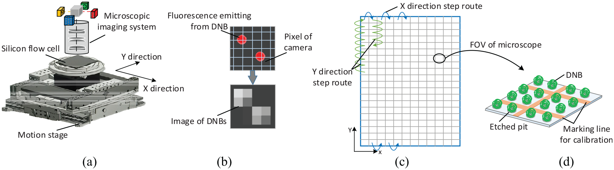
Step-scanning process of the stage for gene sequencing: (a) motion stage carrying flow cell for fluorescent detection, (b) imaging the fluorescence from DNBs after each step motion, (c) silicon flow cell, and (d) DNBs array.
When we define the step scanning speed as the ratio of the sequencing field of view and the step scanning time, it is clear that a higher step scanning speed means a larger amount of sequencing data obtained at the same time. In the entire flow cell scanning path, the Y-direction step occupies the vast majority, and the Y-direction step length determines the sequencing field of view size. Therefore, the step speed in the Y-direction of the stage, that is, the ratio of the step length and the step time, determines the step scanning speed of the entire stage. So the subsequent content of this paper only discusses the control method of the stage for the Y-direction movement.
Dynamic model of gene sequencing stage
The motion of the stage is propelled by a surface-mounted slotless permanent magnet synchronous motor (PMSM). A high-performance power driver is employed to drive the motor, and a high accuracy scale is equipped to provide the position feedback of the stage. The error caused by the motor driver and the scale is so small that we ignore the influence on the control accuracy in this paper. Here we build the dynamic model with current closed-loop control of the stage in the d-q coordinate system, as shown in Figure 2.
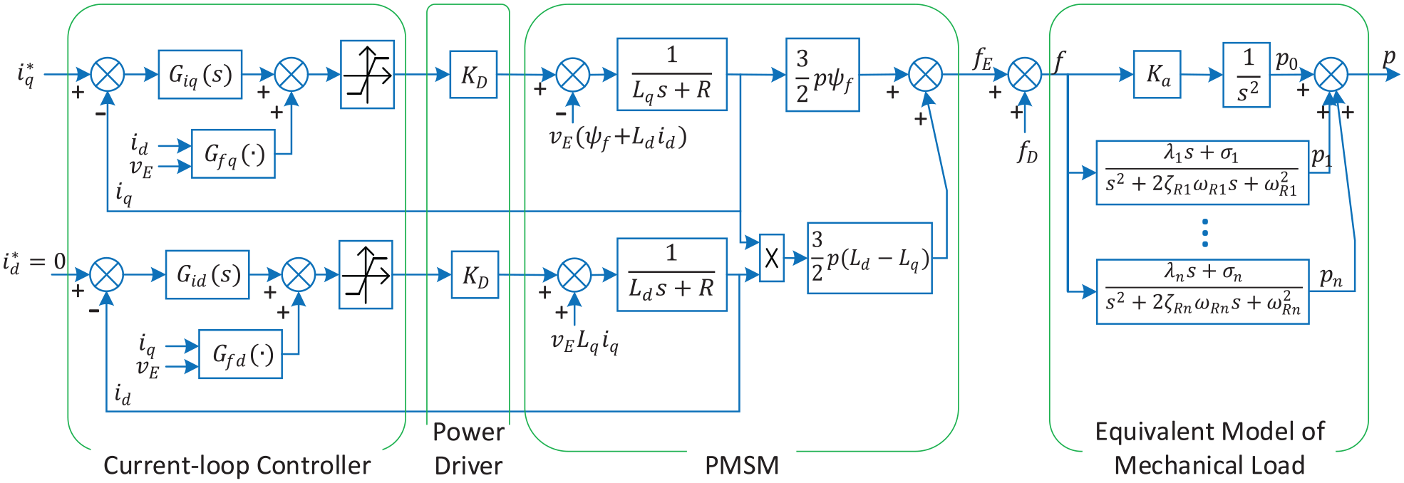
Dynamic model with current closed-loop control of the stage.
In Figure 2, the q-axis reference current
(1) Current-electromagnetic force transformation
This conversion is from control current to electromagnetic force under the current closed-loop control, which is composed of the current-loop controller, power driver, and PMSM. The current-loop controller usually adopts the combination of PI control and feed-forward compensation control. 17 The PI current controllers of q-axis and d-axis often use the same parameters, namely:

Where kp and ki are proportional and integral coefficients respectively.
18
The d-axis feed-forward term represented as


Where
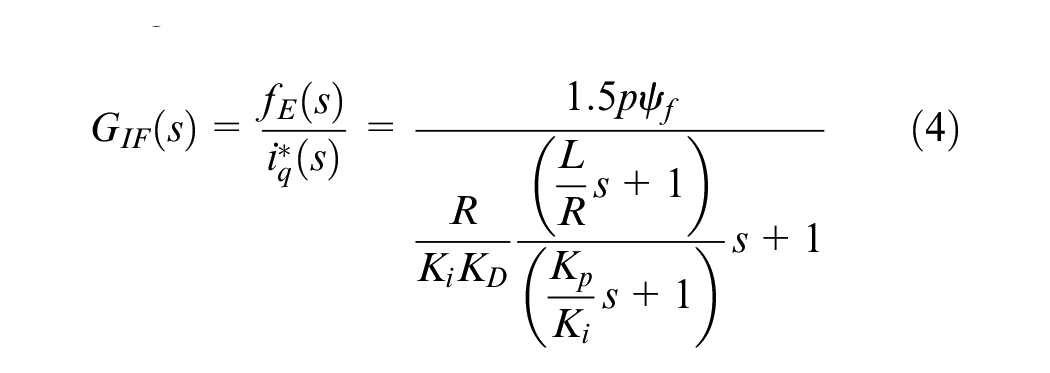
Where R is the coil resistance; p is the number of pole pairs; KD the power driver amplification factor. If we design kp/ki = L/R, GIF(s) is further simplified to first-order form:

Where
(2) Force-displacement transformation
Under the action of the driving force, the stage does not move according to a pure rigid body. On the contrary, the mechanical parts of the stage always have elastic connection with each other. The motion load can be approximately equivalent to a multi-freedom degree damping system, and the displacement response of load exists multi-order vibration components. The driving force f and the displacement p measured by the high accuracy scale operate on the same single point of the load approximately. According to the vibration theory, the relationship between the force and displacement can be described by the transfer function as follows 20 :
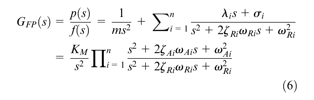
Where m is the load mass;
Controller design
Idea of the VSC
For the implementation of step motion, we usually draw up a shortest time state transition trajectory in advance and control the stage to follow it. Due to the existence of response lag, model errors, and unknown perturbation terms, the stage always deviates from the trajectory in the early phase of step. In FSC, the final position and step length of each step is determined, so in the late phase of step, the control goal is not only to make the stage reach the desired final position, but also keep a still state afterward. For VSC proposed here, the final position of each step is an arbitrary value within a specific range. The control goal is just to make the stage quickly enter the restraint range and then keep a stationary state. The control goal of VSC is looser, which needs less adjusting time in the late phase of the step.
Of course, the VSC will probably cause larger static error than FSC, and the static error may increase the step length of the next step. However, the early phase of step motion is usually a large acceleration and deceleration movement, and the average speed is much larger than the late phase of step motion which is convergence and stabilization. The step increment brought by the static error of VSC is covered in the large acceleration and deceleration phase of the next step, which takes less time than FSC to reduce it in the late phase of step motion. As a whole, the step motion efficiency of VSC will be higher than that of FSC.
PID control system for the VSC
As the control structure of PID with feed-forward is commonly used in FSC, we also propose a VSC based on PID with feed-forward here to facilitate comparison, as shown in Figure 3.
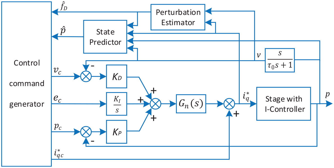
Block diagram of variable step PID with feed-forward control structure.
In Figure 3, the controlled object is the stage with the current loop. Gn(s) is the notch filter. The position closed-loop proportional controller KP, the speed closed-loop proportional controller KD, and the integral controller
(1) Early phase of step motion
In the early phase of step motion, the goal of VSC is to move the stage from the present scanning position to the vicinity of the next scanning position in the shortest time. For the force-displacement conversion model described in equation (6), if we ignore the multi-order vibration mode term, the model degenerates into a double integral system. According to the optimal control theory, to transfer the double integral system from one stable position to another stable position, the minimum-time control amount should be taken at the boundary and the sign changed once. Without loss of generality, when the increment of the state transfer position is positive, the minimum-time control amount fm is shown as follows:
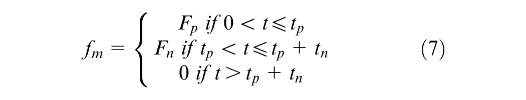
Where Fp and Fn are the positive and negative boundary values of control amount; tp is the action time of positive control amount; tn is the action time of the negative control amount. However, when the square-wave period of positive and negative control amount is close to the fundamental-frequency period of the microscopic imaging system, the impulse of the control amount will cause slight shaking of the microscopic imaging system, which deteriorates the imaging clarity. To avoid this adverse effect, the cut-off time of positive and negative control amount is often staggered from one fundamental-frequency period of the microscopic imaging system. The oscillating response caused by the positive and negative impulse will be canceled each other. At this time, the control amount fm becomes:
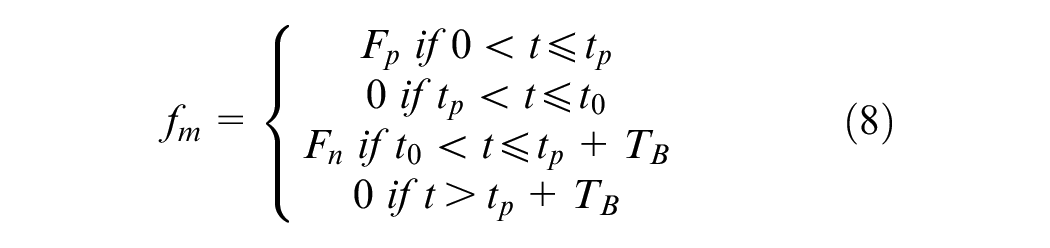
Where TB is the fundamental-frequency period of microscopic imaging system;
The control current usually has the same positive and negative boundary values, 21 so we have:

Where Imax is the maximum allowable control current. If the external disturbance
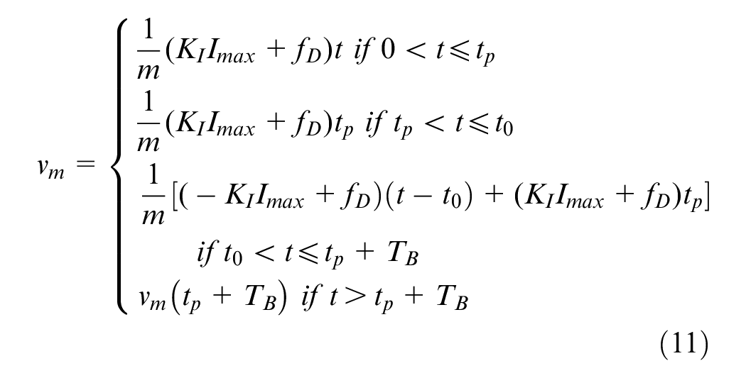
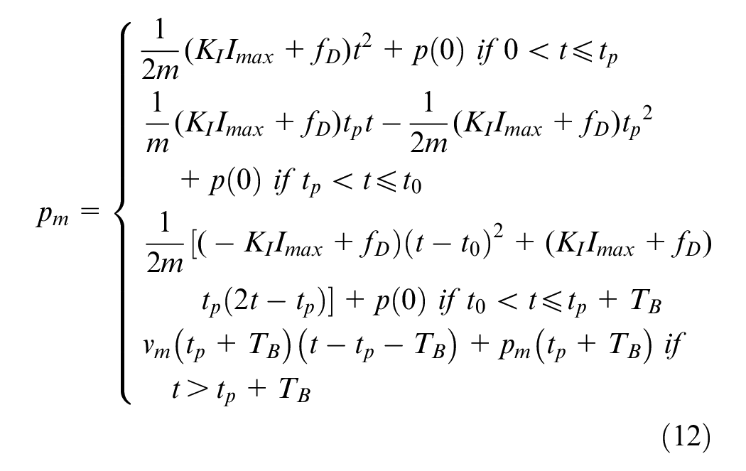
Where

The driving force becomes:

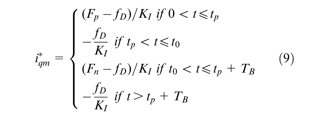
Where hI(t) is the impulse response of current-loop inertia function in (5). At this time, the stepping speed and displacement become:


Where the final stable values of vc and pc are the same as those of vm and pm. Equations (13), (15), and (16) give the feed-forward command
Where
(2) Later phase of step motion
Suppose that the length of the convolution function h(t) is NT, then at the time of tp + TB + NT, the feed-forward command
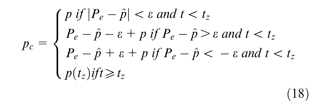
Step1: Start the state predictor. If the absolute deviation between expected position Pe and predicted steady-state position
Step2: Set
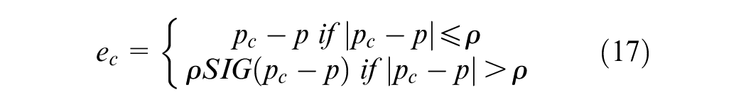
Step3: During the process toward steady-state, the position closed-loop proportional control becomes the auxiliary adjustment function so that the steady-state position of the stage does not deviate from the allowable neighborhood range of the expected position. Concurrently, the integral controller is canceled gradually to speed up the steady-state process. After entering the steady-state, the position closed-loop proportional control, the speed closed-loop proportional control and the integral controller work together to form a high gain PID controller to improve the anti-perturbation ability. pc and ec are set as:
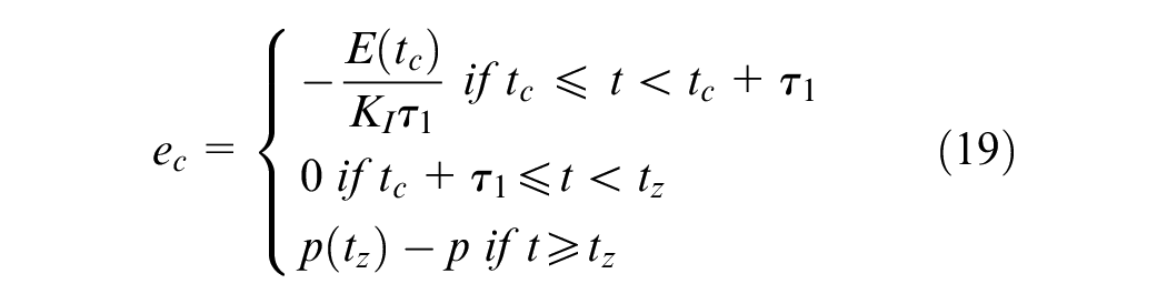
Where
(3) Perturbation estimator
The external perturbation force is estimated by the current value
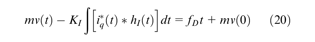
Set

This formula is a time linear function with fD and c as parameters. At any sampling time kT, the corresponding y(kT) value can be calculated according to the current value
(4) State predictor
The state predictor predicts the steady-state position of the stage under the action of single-speed closed-loop proportional control. On the condition of ignoring the influence of multi-order vibration mode, the system state equation with
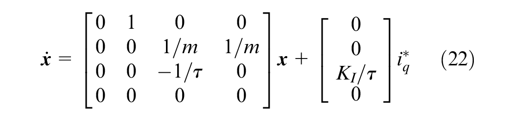

Where
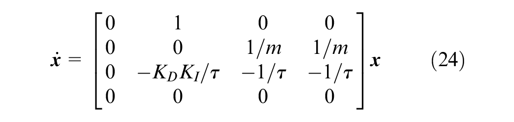
After discretizing equation (24), from the current state we can recursively calculate the predicting state
Experiments and methods
Parameters and evaluation metrics
To justify the control performance of VSC, a motion model is well constructed based on the features of the existing gene sequencing stage which has been used in the IMA6000 gene sequencer prototype. The parameters are listed in Table 1.
System parameters.
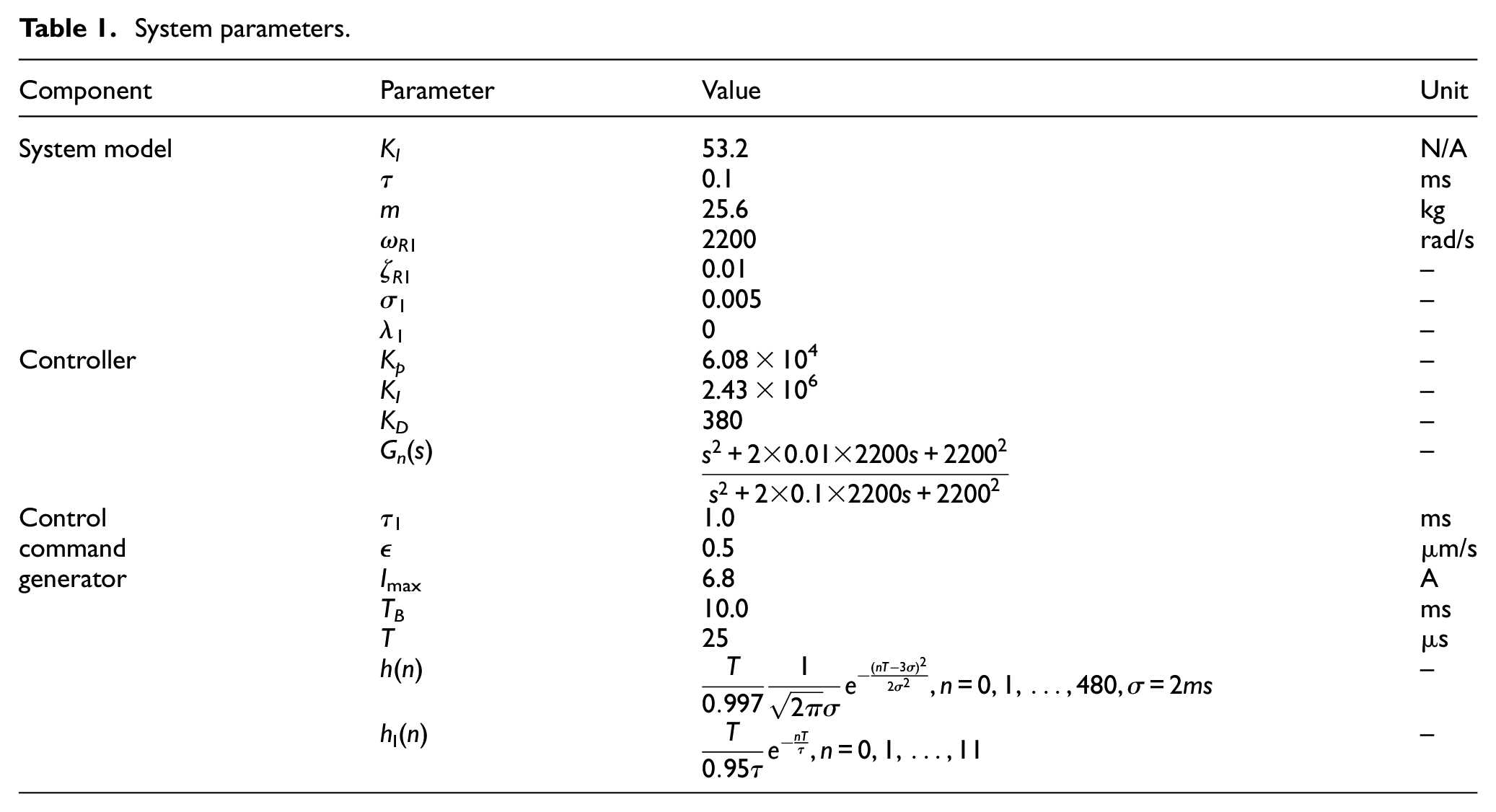
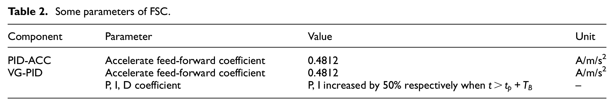
Also, we choose two typical FSC controllers, that is, PID-ACC and VG-PID, and compare them with VSC through simulation. Among them, the PID controller of FSC is the same as VSC, and other relevant parameters are set in Table 2.
Some parameters of FSC.
In the simulation, the expected step length is 1.512 mm, and the steady-state interval of VSC is −1 to 1 µm. The allowable threshold
Settling time. It refers to the time consuming of the step motion to the steady-state. Here, the steady-state is defined as the absolute deviation between the continuous N sampling position and its mean value is less than the set value, that is
Steady-state error (SSE). It is an absolute deviation between the expected position and the steady-state mean position, that is,
Scanning speed. It is referred to as the ratio of real step length and settling time.
Simulation analysis
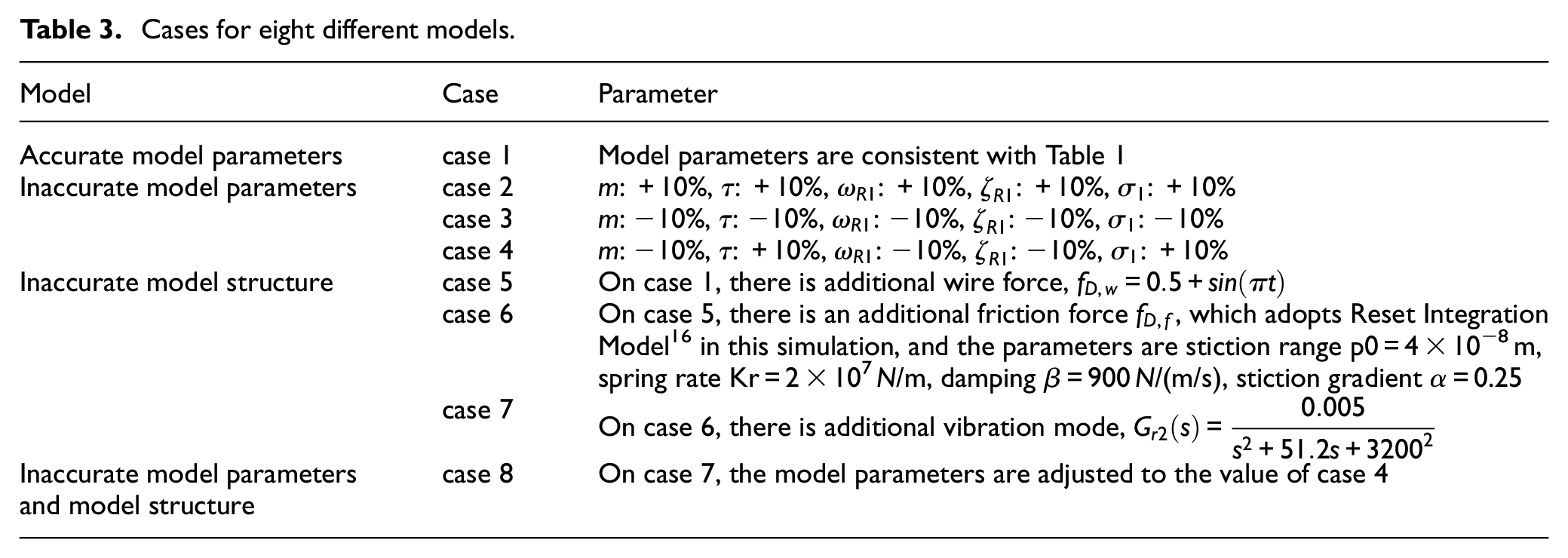
In the application of the real gene sequencer, the parameters of the control object will have changes or errors owing to the limitation of instrument measurement accuracy, the change of the test environment or the constraint of the identification method. Here, according to the boundary range of the parameter variation, the different models are selected to analysis the influence of the different possible errors on the system performance. Eight models are exemplified, that is, the model parameters are accurate, the model parameters are not accurate with different deviation, the model structure are not accurate with different deviation, the model parameters and structure are not accurate. The comparative simulation of FSC and VSC is carried out on eight different models and parameters, which are shown in Table 3.
Cases for eight different models.
The step motion curves of VSC and FSC are shown in Figure 4. It can be observed that the starting and ending positions of each step motion for VSC are uncertain, but VSC outperforms FSC in terms of settling time. Specifically, Figure 4(a) shows the stepping curve of case 1. Although the SSE of VSC is more than FSC, it can reach a steady-state in a shorter time, where the cross marks the moment of entering a steady-state. Moreover, FSC will still approach the given position at a very slow speed even if enters a steady-state, while VSC can stabilize at the steady-state position with higher stability precision. Figure 4(b) to (d) show the case 2–4 where the parameters of the system model are inaccurate. The settling time of VSC and FSC increase compared with case 1, but the increment of FSC is more significant. The main reason is that the parameter values required for step command generation are not consistent with the actual model so that the ability of the feed-forward controller is weakened. It should utilize the closed-loop function of the controller and take more time to make the system stable. Besides, the SSE of VSC becomes larger because of the state prediction error caused by the inaccuracy of model parameters, but it does not exceed the preset steady-state interval, which contributes to the position-loop auxiliary adjustment in VSC. For the case 5–7 where exist model structural error, the stepping curves are shown in Figure 4(e) to (g). We can find that the settling time and SSE of VSC and FSC have slight changes in comparison with case 1. It shows that the VSC has the same anti-perturbation ability as FSC. For higher-order vibration model terms, the extra oscillation responses will occur in VSC and FSC during the process of approaching a steady-state. If the oscillation is small enough, just as shown in this simulation, it usually does not require further processing. When the structure and parameters of the system model have changed, we also find that the settling time of VSC is still less than FSC, as shown in Figure 4(h).
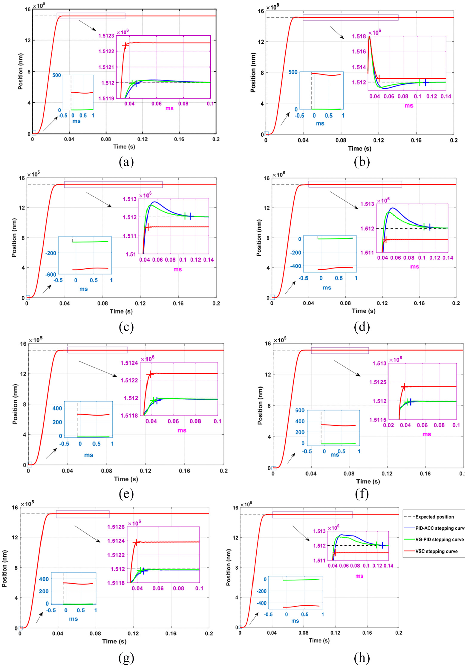
Stepping curves of VSC and FSC: (a) case 1, (b) case 2, (c) case 3, (d) case 4, (e) case 5, (f) case 6, (g) case 7, and (h) case 8.
Furtherly, we investigate the data of the 5000 steps in each case and calculate the average of settling time, SSE and scanning speed. Firstly, settling time, SSE and scanning speed of each step in each case are calculated according to the specification and calculation method of the performance index (a) (b) (c) at the above Section 4.1, and then the same index calculation is done for the data of the 5000 steps. Finally, the settling time, SSE and scanning speed of 5000 steps are averaged respectively. The statistical curves of the performance comparison index are shown in Figure 5. It can be observed that VSC makes improvement in settling time and scanning speed, especially the settling time is almost unchanged. This feature is much suitable for practical applications, which usually consider that the stage will be in a steady-state at a constant moment. Admittedly, the SSE of VSC increases greatly during the step-scan motion compared with the FSC, but it is always smaller than the set tolerance of steady-state interval. Indeed, the scanning speed of the VSC is still increased by nearly 8% in the case of accurate model parameters. Normally it takes a long time to complete the whole test in the actual working process of the gene sequencer. Although the scanning speed is only slightly improved, it is very meaningful in practical application.
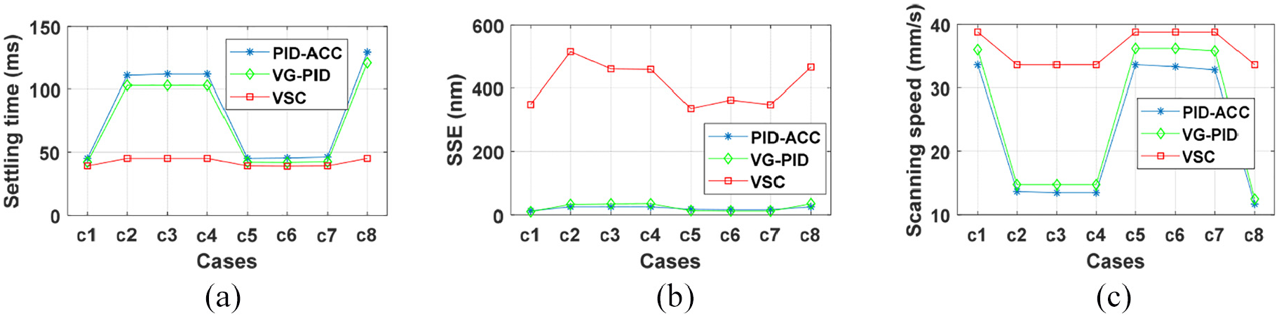
Performance comparison curves in all cases (the average of 5000 steps): (a) settling time (b) steady-state error, and (c) scanning speed.
Implementation on gene sequencing stage
We have applied the proposed VSC to a self-designed X/Y/Z 3D-motion gene sequencing stage used in the IMA6000 gene sequencer prototype, as shown in Figure 6. The Y-axis movement of the stage is jointly driven by two identical surface-mounted slotless PMSM. Each motor is controlled by an independent current loop for commutation, but the q-axis control current is the same. Therefore, the parameters of the dual-motor drive are exactly similar to the single-motor drive except the equivalent gain of the current loop is doubled. A high accuracy linear scale with a 20 μm pitch is used for position feedback. Each pitch signal is divided into 8000 equal parts and the corresponding position resolution is 2.5 nm. The control operation runs on the TI-TMS320F28377D dual-core microcontroller, the sampling frequency is 40 kHz, and the motor drive mode adopts three-level SVPWM inverter.
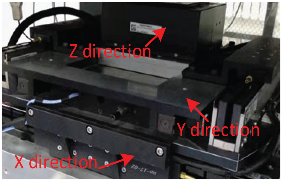
X/Y/Z 3D-motion gene sequencing stage.
The experiment is carried out according to the requirements of gene sequencer. The expected step length of VSC is set as 1.512 mm, and the allowable range of step change is ±1‰ step length, that is, −1.5 to 1.5 μm. According to scanning speed requirements, we choose 60 ms as one step cycle, in which 50–60 ms is defined as the steady-state period and the camera is exposed to the DNBs fluorescence. The data comes from the feedback position of the stage’s own linear scale. The expected position and the feedback position of the scale are recorded with 0.1 ms sampling period, and the curve for some data is shown in Figure 7. Furthermore, counting all the recorded data during the steady-state period, we can obtain the distribution of some performance metrics in Figure 8, that is, SSE, the peak-peak value of feedback position and the standard deviation of feedback position. It can step 1.54 mm in 50 ms period in the analyses of data. For most steps, the SSE is less than 0.8 μm in Figure 8(a), the peak-peak value of feedback position is less than 120 nm in Figure 8(b), and the standard deviation of the feedback position is less than 30 nm in Figure 8(c), which can meet the sequencing accuracy requirements.
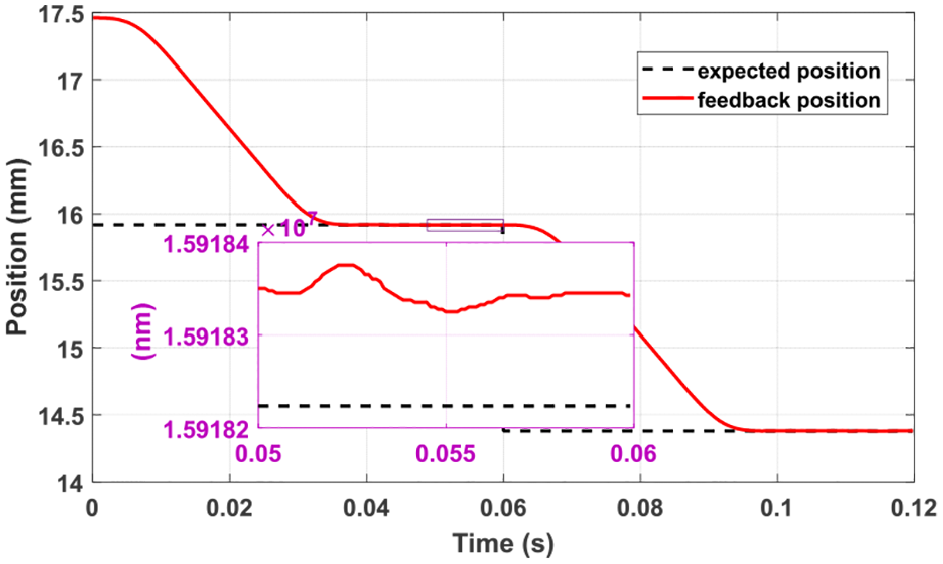
Recorded position curve from the linear scale.
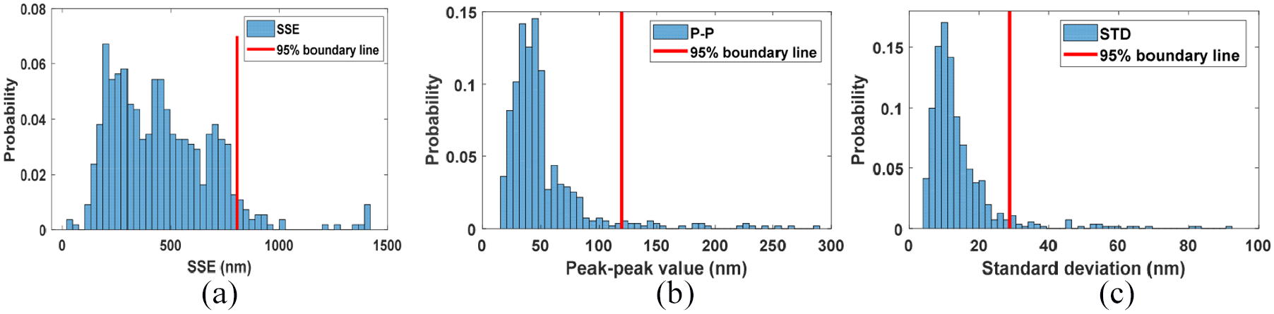
Distribution of the performance metrics from the linear scale: (a) SSE, (b) peak-peak value, (c) standard deviation of feedback position.
In addition, we choose a laser interferometer to measure the position of the stage, and the data collected by the interferometer are analyzed. The test platform for the gene sequencing stage is shown in Figure 9. The expected position and the feedback position of the laser interferometer are recorded with 0.2 ms sampling period, and the curve for some data is shown in Figure 10. Then, the data from 90 to 100 ms are counted. In the stable period of 10 ms, the peak to peak value of the steady-state error of most steps is less than 170 nm in Figure 11(a) and (b), and the standard deviation is less than 55 nm in Figure 11(c) and (d), which can meet the application requirements. It should be noted that there is the step errors, as shown in Figure 7 and Figure 10, which is allowed in practical applications. Compared with the existing errors, the stable shooting and clear imaging are more important in practical applications. Moreover, the step errors can be easily eliminated by the mark line alignment method in the subsequent image processing process.
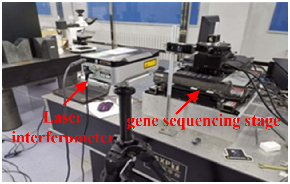
Test platform for the gene sequencing stage.
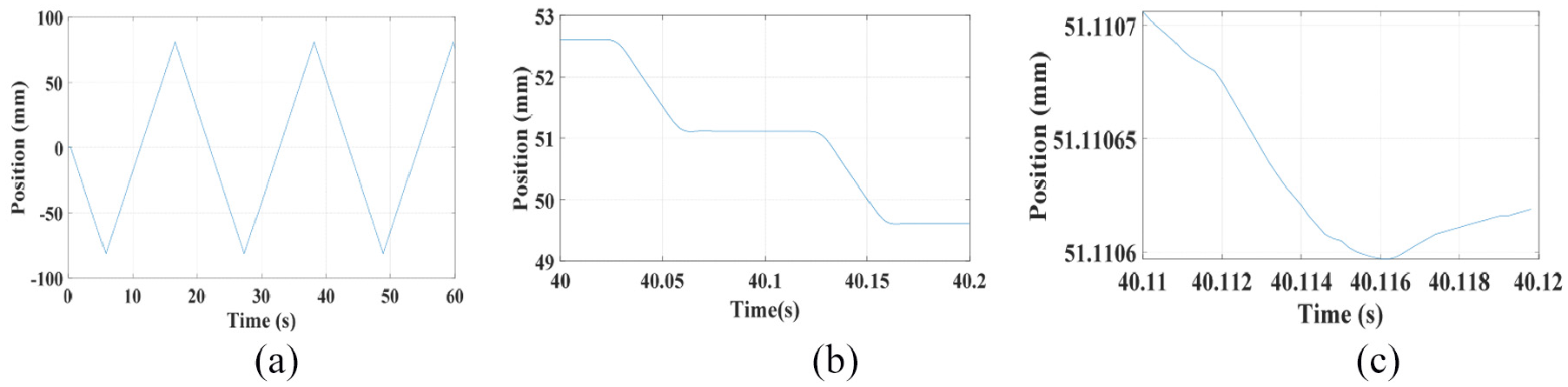
Recorded position curve from the laser interferometer: (a) 0 s-60 s, (b) 40 s-40.2 s, (c) 40.11 s-40.12 s.
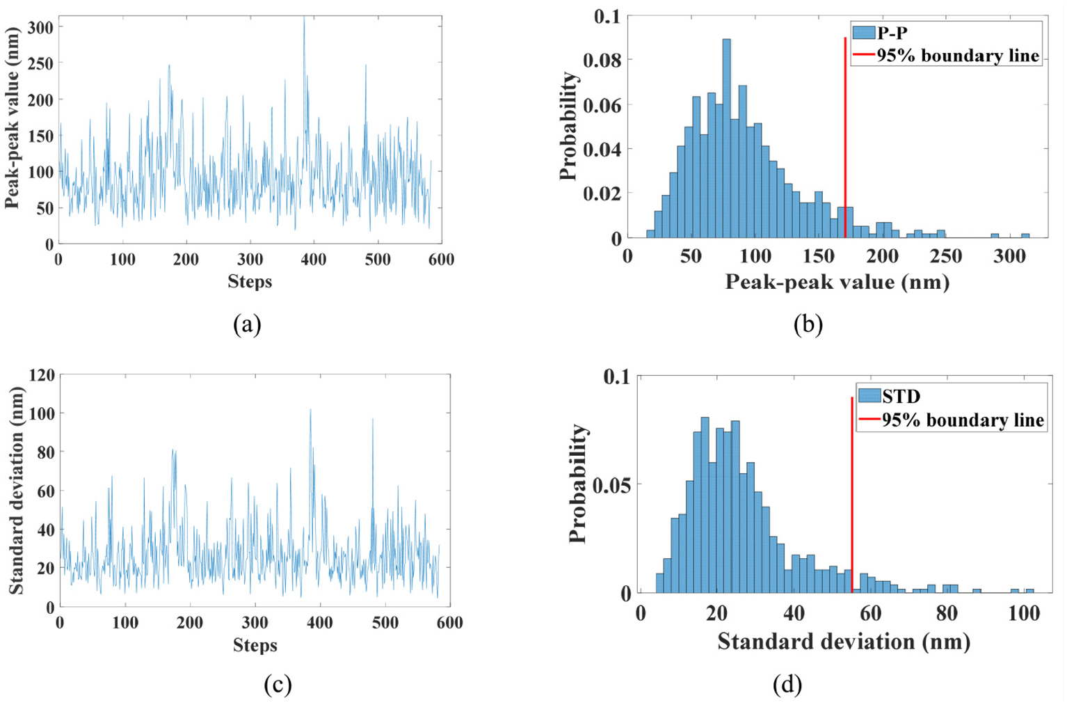
Distribution of the performance metrics from the laser interferometer: (a) peak-peak value of different steps, (b) distribution of peak-peak value, (c) standard deviation of different steps, (d) distribution of standard deviation.
Conclusion
In the present research of the gene sequencer, an attempt has been made to achieving high-precision position stability with minimal settling time. We proposed a novel variable step control to improve the scanning efficiency of the gene sequencer. This method allows the final position of the step motion to be anywhere within the steady-state interval instead of the preset position. The stabilizing process was accelerated at the later phase of step motion and the settling time was reduced. In order to prevent the accumulation of errors and improve the overall scanning speed, the step error of each step motion caused by variable step control will be compensated in the early acceleration and deceleration phase of next step motion. The experimental results show that the variable step control can obtain less setting time than PID-ACC and VG-PID control methods. The superior performance maintains even if there are disturbance or changes in the parameters and the models. The variable step control may be helpful to related fields such as fast microscopic industrial measurement. Future work consists on the study of the effects of the variable step into the optimization process in order to promote even more the accuracy in the desired scanning efficiency.
Footnotes
Declaration of conflicting interests
The author(s) declared no potential conflicts of interest with respect to the research, authorship, and/or publication of this article.
Funding
The authors disclosed receipt of the following financial support for the research, authorship, and/or publication of this article: This work was supported by the National Key Research and Development Program of China [grant number 2019YFC1804805-4]; the Changchun Key Scientific and Technological Projects of China [grant number 18SS014]; the National Natural Science Foundation of China [grant number 42074178]; and the Education Department of Jilin Province of China [grant number JJKH20200945KJ].