
Abstract
In an automated steering system of the self-driving vehicles, the steering wheel angle is measured by the absolute angular displacement sensors or relative angle sensors. However, these sensors either encompass global navigation satellite systems (GNSS)/gyroscope – Micro Electromechanical-Sensor (MEMS) based solutions or comprise of the complex gear-based mechanical structure which results in latency and additive bias in the accumulative steering angle assessment. To address these issues, we propose a novel steering angle assessment system based on enhanced gear mechanism along with the adapted rotation paradigm for the customized self-driving vehicles. Additionally, a digital signal processing system has been introduced to resolve the issues in the identification of absolute central and max-bounding steering wheels position in self-driving vehicles. In assistance with the proposed mechanism, an algorithm has also been proposed to optimize the computed steering angle to minimalize the effect of additive bias in the accuracy. The proposed mechanism has been installed in the customized self-driving testbed vehicle and rigor validation has been performed in the straight and curvy road scenarios. Finally, the comparison study has been carried out between the conventional relative sensor and the proposed mechanism to show the accuracy and effectiveness of the proposed mechanism in terms of error rate, stability, and deviation.
Introduction
Steering wheel angle assessment is one of the most critical aspects of the Electric Steering Control (ESC) system which plays an important role in lateral stability control and safety of Autonomous Vehicles (AVs). Angle sensors that is, Accelerometers, yaw angle/rate sensors, and steering wheel positioning sensors provide the input data to the ESC system in the form of signals. The ESC system processes the received information and performs the control action accordingly. These sensors are considerably fast enough to retort the minimal rate of change in the lateral rotation/displacement in the steering wheel of the vehicles. 1 In the last couple of decades, the steering wheel angle estimation sensors have been classified into two categories: (i) absolute angular displacement sensor, and (ii) relative angle sensor. 2
Certain absolute angle displacement sensors (ADSs) that is, Magnetic or electrical measure the rate of change in position between the designed range without any reference point. In a research study, non-contact inductive based ADS has been proposed to compute the steering angle by measuring the displacement in the planar sinusoidal-shape coils between the stator and rotor of the sensor. 3 In another research work, the Fiber Optical Displacement (FOD) based theoretical model of ADS has been proposed which measures the angle by subtracting the two positive power signals from fibers attached to both sides of the emitting fiber phase. 4 However, these absolute ADSs are made up of complex electro-mechanical structure which influences the accuracy of the steering angle measurement through continuous backlash in the gear mechanism. 5 These issues of ADSs lead to an increase in the error rate in the measurement of the steering angle which can cause instability in the dynamic steering control system of the vehicle.
Relative angle sensors have been proposed to address the additive bias and malfunction issues in the existing proposed steering angle sensors. In this regard, Multi-Track Encoder (MTE) based Torque Angle Sensor (TAS) has been proposed to measure the steering angular position along with the applied torque with minimal error rate as compared to the conventional TAS module. 5 In another research work, GNSS and the gyroscope-based mechanism is presented to determine the steering angle by taking two parameters (rate of heading inclination and acceleration rate) into account using Kalman filter. 6 Though, these relative angle sensors have improved the accuracy by reducing the additive bias in the estimated steering angle. However, the GNSS/gyroscope based steering angle measurement systems are much reliant on the satellite data which have signal spoofing, precision, and jamming concerns.7–10 Moreover, the TAS/electro-magnet based steering angle sensors return distorted signals when their positive and negative phase shafts switch arbitrarily which leads to continuous error in estimated steering angle. 11 Besides, the researchers5–11 have not presented any scheme for the practical implementation of these sensors in the steering automation of customized self-driving vehicles.
A novel steering wheel angle assessment mechanism based on enhanced gear-mechanism along with the customized rotary paradigm to improve the effectiveness of the existing commercial relative angle sensor in terms of accuracy, deviation, and stability.
A digital signal processing based absolute central and max-bounding steering wheel positioning system has been proposed for customized self-driving vehicles.
An algorithm has been proposed to optimize the steering angle measurement to minimize the influence of the latency and additive bias in accuracy.
The prototype of the proposed mechanism has been installed in the customized self-driving vehicle and in-field rigor analysis has been performed to validate the effectiveness of the proposed system.
The rest of the article is organized as follows. An extensive study of the related work is elaborated in Section 2. The proposed method including the system architecture, the working principle, and the algorithm is provided in Section 3. The experiments and results of the conventional sensor and the proposed system are discussed in Section 4. Finally, Section 5 concludes the work.
Related work
In the last couple of decades, extensive research on steering wheel angle estimation sensors has been carried out to improve the accuracy and stability in the angle positioning sensors. The existing state-of-the-art angle sensors are categorized into absolute and relative angular measurement technologies for the positioning of steering wheels of the vehicle. To provide an in-depth overview of these technologies, we categorize the literature review into two threads.
In the first thread, we discuss the concerns related to absolute ADSs and their subtypes. Some of the traditional steering control mechanisms employ inductive ADSs. These sensors belong to the family of absolute ADSs and preferred due to their good lifespan and suitability in harsh industrial environments. In the literature, seminal contributions in Refs.3,12–14 have been made by researchers in developing the ADSs. An inductive angular sensing technology based on eddy current with full circle range is presented in Kumar and George. 12 The authors have developed a simple yet effective algorithm to acquire the angular rotation of the shaft considering four inductance parameters. An inductance-based shaft angle sensor is developed by Anandan et al. 13 In their proposed sensor, five coils have been utilized while four of them are stationary and arranged in cylindrical quadrants. Whereas, the fifth coil is the moving coil and placed around the flexible planner coils. The rotational displacement is determined by measuring the voltage induced in the fifth coil. An angle sensor measuring the absolute angular position is presented in Reddy et al. 14 They have implemented the layout of the proposed coil on a bi-layer PCB and a thin steel disk and validated the proposed design using an inductive sensor interface device. While in Tang et al. 3 the authors have presented a non-contact inductive sensor along with its working principle. Their proposed technology employs sinusoidal shaped primary coils to generate the magnetic field. This is, in turn, helps to determine the sinusoidal distribution between the rotor and the stator. However, the sensing range of the inductive ADSs presented in Refs.3,12–14 depends upon the type, size, and shape of the metal to be detected and the size of the coils used in the design. Due to this reason, it has distance limitations for sensing and can only detect metallic targets. Moreover, these sensors require complex circuits consisting of many resistors, electronic switches, and precision op-amps which increases the production cost of the sensors up to 30%.
Additionally, optical sensors are the third well-known type of absolute ADSs due to their ability to provide high resolution in the assessment of the rotation angle. In Ghaffar et al. 15 the authors have developed a simple and cost-effective optical fiber angle measurement sensor. Due to its flexibility, they have utilized polymer optical fiber in the experiments. Therefore, the proposed sensor should be considered for dynamic angle measurement. In Jia et al. 16 a novel optical fiber ADS is proposed exhibiting differential reflective properties. The proposed sensors measure the axial and angular linear displacement of a flat surface. In Shan et al. 4 another differential reflective fiber-optic for the measurement of angular displacement. Two power signals are subtracted from the receiving fibers mounted on both ends of the emitting fiber. While in Twu and Yan 17 an optical angle has been developed which is based on immersion type potassium titanyl phosphate. This sensor helps to determine the angular displacement in a homodyne interferometer. However, numerous optical elements are required for the angular measurement; hence, the volume of the measurement sensor needs to be reduced. Moreover, the performance of the sensors developed in Refs.4,15–17 is affected by a harsh and dusty environment.
While in the second thread, we discuss the relative angle sensors based steering wheel angle estimation using micro-electro-mechanical systems (MEMS), global navigation satellite system (GNSS), etc. In Kim et al. 18 the authors have proposed a novel steering wheel angle estimation method based on torque overlay for lane-keeping of the self-driving vehicles. The proposed system has enhanced the yaw rate ripple for the lateral control system as well as the steering angle. However, the steering control could have been further improved by also introducing longitudinal control. An improved TAS module-based vehicle steering control has been proposed in Woo et al. 6 to improve the state-of-the-art TAS module with a fewer number of physical components and has shown increased performance with minimum angle estimation error as compared to the previous steering angle modules. However, they did not consider the utilization of the steering angle module in steering automation of the customized autonomous logistic vehicles. A novel GNSS and MEMS-based steering angle estimation method is proposed in Miao et al. 7 The output from these sensors is given as an input to an adaptive Kalman filter to correct the errors precipitated by a gyroscope. This system has improved the performance as compared to hall sensors by 1°. Although, this system has performed well, the authors should have considered to find out the central and maximum steering bound position estimation of steering wheels of the self-driving vehicles. In another research work, 19 the MEMS-based steering angle sensor has been proposed to minimize the error rate that is, Bias and side slip in the accumulative angle using Kalman filter. However, the authors have not evaluated the performance of the proposed system in the real-time road scenarios. In addition, they have not presented any practical scheme for the implementation of the proposed system in the real-time on-road dynamic scenarios. Whereas, these parameters play a vital role in steering control of self-driving autonomous vehicles.20–24
Method
Structure and working principle of the proposed system
The proposed steering wheel angle sensor mechanism, depicted in Figure 1, comprises of gear mechanism along with the customized rotary shaft, and sensing central and max-bounding steering positions. A prefabricated commercial rotary encoder is mounted on top of the rotary shaft attached to the steering wheel axle of the vehicle.
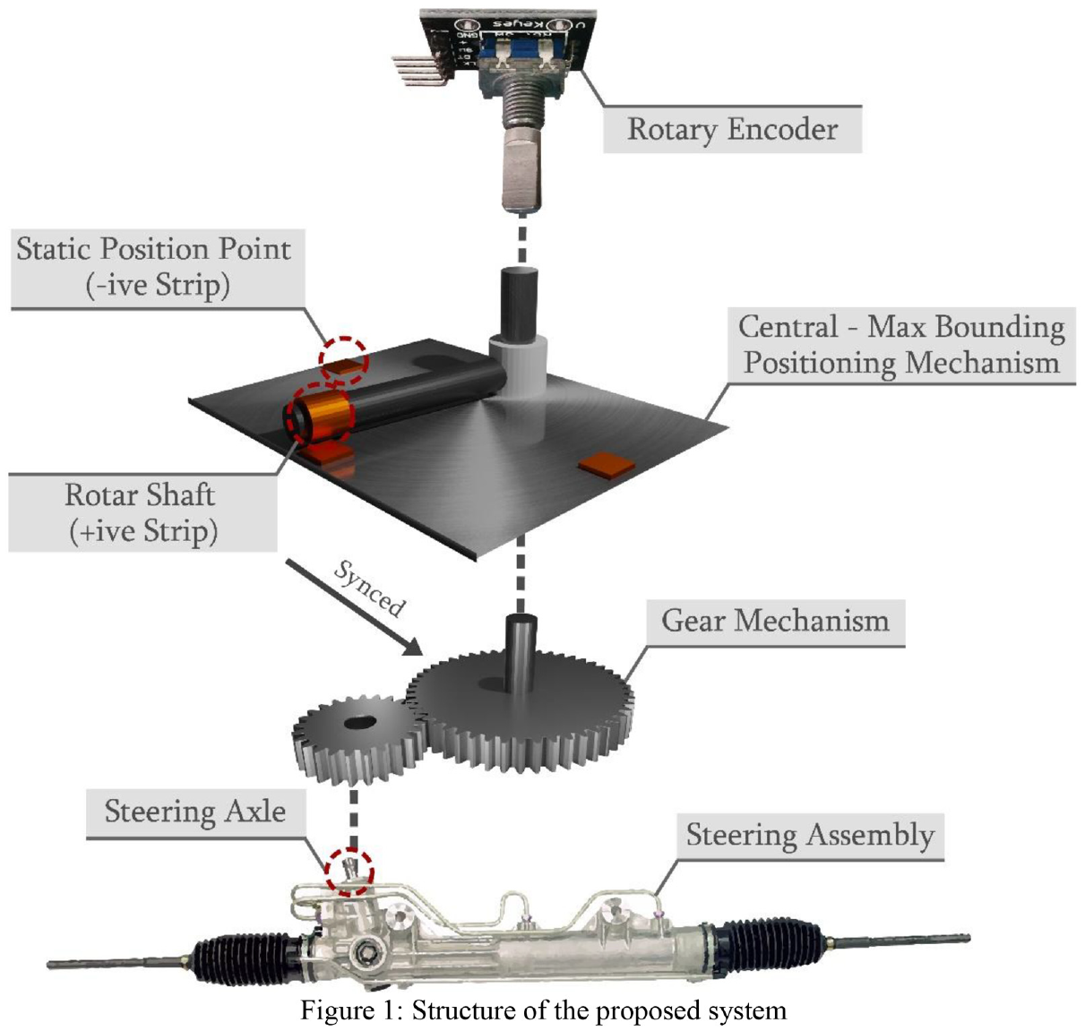
Structure of the proposed system.
In the proposed mechanism, two steel gear wheels of 1:4 ratio are developed and fixed over the steering axle of the front steering wheel assembly of the vehicle to smoothen the effect of wheel rotation on the encoder to minimize the additive bias and backlash simultaneously. The ratio of the gear wheels is expressed using equation (i).
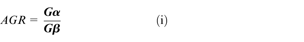
Where,
G
Therefore, the rotation angle estimated on the latter is equivalent to one-fourth of the steering shaft rotation which indicates that one full-scale rotation of the gear wheel is mapped on the four times rotation of the steering wheel shaft. A fabricated rotary encoder is used to measure the angular rotation of the steering wheel, mounted on top of the rotor gear wheel. The accumulative steering angle with respect to time is obtained using equation (ii).

Where,
According to the characteristics of the rotary encoders, additive bias occurs due to random drift in the steering wheels during the movement of a vehicle which leads to a continuous error in the accumulative steering angle over time. This additive error is removed using equation (iii).

where,
By deriving the equation (iii), we express the actual steering angle using equation (iv).

To calculate the central and max bounding positions of the steering wheels, an electric charge-based strip mechanism is devised. Three static electric strips having positive (+ive) electric charge are installed in the above-mentioned positions and a rotor shaft having negative (-ive) electric charge strip is fixed over the gear mechanism and synchronized with the rotation of the wheels, expressed in equation (v).
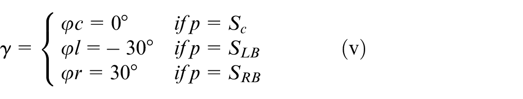
where,
p − position of the rotor
The rotor shaft mounted on the gear wheel spins with the rotation of the steering wheel and generates a digital signal when it drifts over the static charged strips position on the mechanism. The position of the rotor is expressed by equation (vi).

where,
In the last step, the estimated steering angle is corrected by equating the equations (v) and (vi).
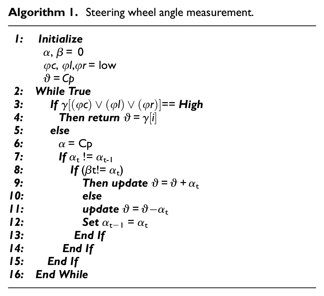
The proposed steering angle estimation algorithm:
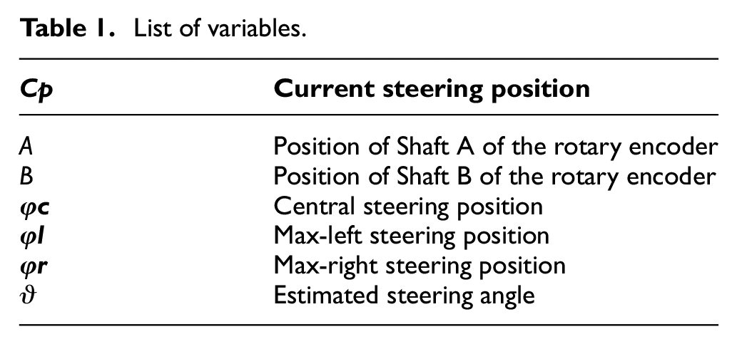
In a rotary sensing module, a digital signal processing system is also required which can detect the change in position and measure the rate of change to assess angular rotation accordingly. In this regard, we have devised an algorithm to measure the steering angular rotation of an autonomous vehicle, as shown in algorithm 1 (Table 1). In the first step, the system initializes the current steering position “
List of variables.
Experiments and results
Sensor prototype & circuit setup
To validate the effectiveness of the proposed sensor mechanism in terms of precision and stability, we have designed a prototype of the proposed mechanism along with its circuit architecture, shown in Figure 2. It can be seen in Figure 2(a) that the gear mechanism is enclosed between the steering assembly fitting and rotor shaft layer of the dimension of 250 × 280 mm. It is important to mention here that the gear wheel of 40 mm diameter is fixed at the steering axle of the vehicle, whereas the rotor shaft and rotary encoder is fixed on the other gear wheel of the diameter of 160 mm to avoid the noise and instability situation occurred due to terrain. The teeth ratio along with its mathematical formulation has been briefly discussed in the method section. In the cover layer, the electric strips are installed, and the rotor shaft is fixed at the height of 10 mm from the strips to ease the rotation of the rotor to avoid rotor-strip stuck issues. In the top layer, the prefabricated rotary encoder is installed which is mounted on the central rod fixed on the gear wheel to note the steering wheel rotation angle.
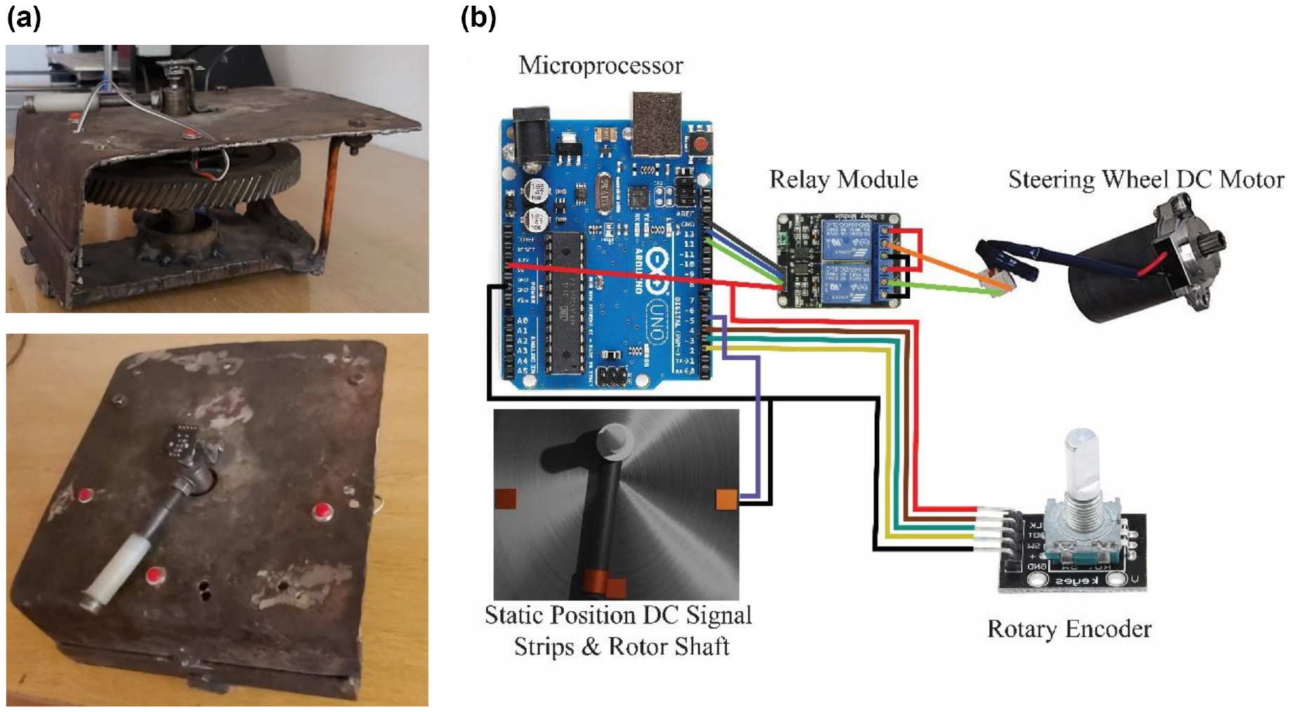
(a) prototype mechanism of proposed sensor and (b) circuitry architecture.
The steering wheel rotation (clockwise/counter-clockwise) is controlled by connecting the steering electric motor with the switching relay module, as shown in Figure 2(b) which is followed by the microprocessor. The rotary encoder and electric strips are connected to the microprocessor which sends the current position data through data pins in the form of signal. The proposed algorithm (discussed in the method section) converts the provided signal data into quantitative measurable angle unit and returns to the autopilot for the assignment of the next instruction accordingly.
Self-driving testbed setup
An experiment platform comprising of customized autonomous industrial logistic vehicle, depicted in Figure 3(a) equipped with the ultrasonic, LiDAR and camera sensors, and high-performance computing machine is setup to verify the effectiveness of the proposed steering angle sensor mechanism. The sensor prototype mechanism is installed in the steering assembly (length of 44 inches) of the vehicle. A round elbow-shaped steel fitting (50 × 50 mm) shown in Figure 3(b) is designed to fix the mechanism over steering axle. The main purpose of installing this fitting is to stabilize the mechanism while vehicle is driving through undesiring road conditions. It is important to mention that it is portable fixing which make insertion and detachment of mechanism flexible and error free. An industrial road alike testing track is designed to perform real-time practical validation of the proposed mechanism is shown in Figure 3(c).
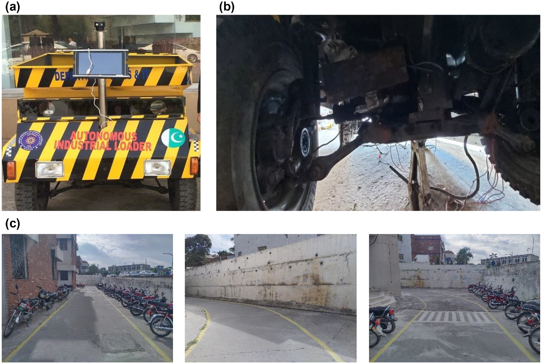
Platform setup: (a) customized autonomous industrial logistic vehicle, (b) angle sensor mechanism fixed with the steering assembly and (c) industrial terrain inspired testing track.
Results
The proposed mechanism is validated by testing the autonomous industrial vehicle on the straight and curved testing track as shown in 3c. Firstly, the ground truth of the steering angle of the vehicle is collected on the testing track. In the next step, the data on the proposed angle sensor mechanism is collected by driving the vehicle on the same testing track and calculated the accuracy of the proposed mechanism by comparing the output value with the ground truth. Secondly, the output angle of the conventional rotary encoder has been validated with the output of the proposed mechanism. The results of the performed experiments are briefly discussed below.
Experiment A: Testing on straight road
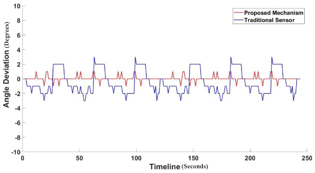
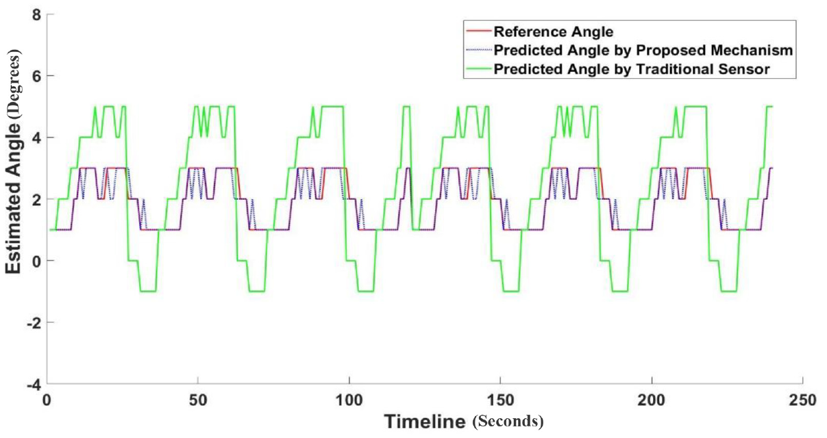
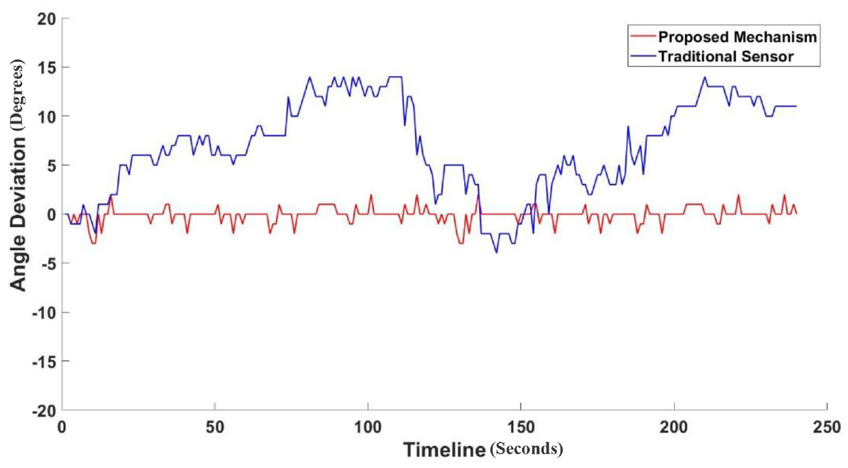
The autonomous industrial logistic vehicle has been driven for 240 s on the straight track of 0.4 km with variable velocity (between 14 to 25 rotation per minute) as shown in Figure 3 to evaluate the performance of the proposed sensor and the conventional angle sensor. The reference angle of the road track has been manually measured in 8° intervals to verify the output steering angle of conventional sensor and proposed angle sensor mechanism. The main purpose of reference angle collection in 8° interval is that test track is not exactly 0° straight; varies between 0° and 8°. In Figure 4, the estimated steering angle using proposed mechanism and conventional angle sensors is measured w.r.t reference angle. The output steering angle of conventional sensor at 5 s in timeline indicates that the bias has been added by 4° w.r.t reference angle which accumulated over time and varies from 5° to −1° in 240 s. The main reason for additive bias observed while experimentation is occurrence of vibration in rotary shaft of steering assembly due to terrain conditions. Owing to undesired vibrations in steering assembly, accumulative deviation in steering angle varies from 3° to −3° with respect to reference angle over time as shown in Figure 5. Whereas, in Figure 4, output angle of proposed mechanism demonstrates slight variation of 0.3°, 0.2° and 0.5° at 13 s, 17 s, and 36 s respectively, which did not lead to continuous error over time due to stability in proposed angle sensor mechanism. Resultantly, the deviation in estimated steering angle has been reduced to 1° which proves the effectiveness of the proposed angle sensor mechanism over the conventional angle sensor.
Steering wheel angle estimation with the proposed mechanism and the traditional sensor on the straight road scenario.
Steering wheel angle deviation in the proposed mechanism and the traditional sensor on the straight road scenario.
Experiment invariant B: Curved road
To further validate the effectiveness of the proposed angle sensor mechanism in the complex road scenarios, the experiment drive of 240 s of the autonomous industrial vehicle has been accomplished on the curvy testing track of 0.3 km with variable velocity between 8 and 14 rotation per minute, as shown in Figure 6. The test track is smoothly curved between 45° and 90°– 45° angle. The output angle of the proposed angle sensor mechanism is verified with the manually measured reference angles (−30° to 30° interval) of the testing track. In Figure 6, the estimated steering angle of the proposed angle sensor mechanism and the conventional sensor is measured w.r.t the reference angle. It can be seen at 15 s in the timeline of the conventional sensor that the bias of 10° is added in the output angle w.r.t the reference angle when the wheel rotation reaches the left steering bound. Moreover, at 29 s in the timeline, the bias started accumulating over time because of the occurrence of vibration due to terrain conditions and steering shaft distortion which lead to accumulative 40° output error in 240 s. Resultantly, the accumulative deviation in the steering angle estimation of the conventional sensor has been observed from 15° to −4° w.r.t the reference steering angle as shown in Figure 7. Whereas, on the other side, the output angle of the proposed mechanism in Figure 6 shows the stable output angle with the trivial error of 0.28 w.r.t the reference angle which did not lead to the continuous error over time. In addition, the deviation in the steering angle is also reduced from 1° to −2° w.r.t the reference angle appropriately, as depicted in Figure 7.
Steering wheel angle estimation with the proposed mechanism and the traditional sensor on the curve road scenario.
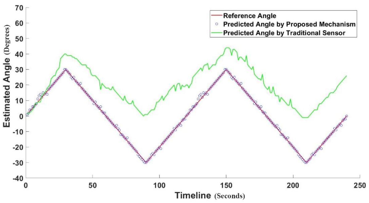
Steering wheel angle estimation with the proposed mechanism and the traditional sensor on the curvy road scenario.
To summarize the comparison of the performance of the traditional sensor and the proposed angle sensor mechanism, the error rate, and the standard deviation have been calculated using standard equations, given in Table 2.
Comparison between the proposed angle sensor mechanism and the traditional sensor in terms of Mean Square Error (MSE) and Mean Deviation.
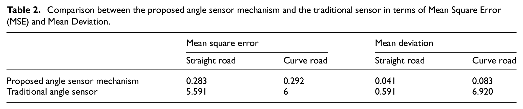
In the above table, the estimated accuracy of the steering angle has been reduced to 0.2% which proves the precision and the effectiveness of the proposed mechanism as compared to the traditional commercial angle sensor. Moreover, the deviation in the steering angle is also minimized to 0.05% which indicates the enhanced stability in the proposed sensor mechanism as compared to the conventional angle sensor.
Conclusion
In this paper, a steering wheel angle assessment system comprising of two-gear wheel and the customized rotary shaft-based mechanism is proposed for the self-driving vehicles to improve the accuracy and stability of the existing commercial relative angle sensor. Additionally, a steering wheel central and max-bounding steering position valuation mechanism has been proposed for the self-driving vehicles. To mitigate the additive bias, an algorithm has been proposed which computes the steering angle and max-bounding positions of the steering wheel. The proposed mechanism has been tested and evaluated on the dynamic straight and curved road scenarios. Results show that the proposed mechanism achieved 99.7% and 99.4% accuracy in the straight and curved road scenarios respectively. Consequently, the significant reduction in the deviation and error rate in the proposed mechanism has been observed as compared to the commercial sensor.
Footnotes
Author’s Note
Muhammad Atif Butt, Faisal Riaz, Samia Abid and, Sarmad Shafique are now affiliated with
1. Control, Automotive and Robotics Lab, Affiliated Lab of National Centre of Robotics and Automation (NCRA), HEC, Islamabad, Pakistan.
2. Department of Computer Science and Information Technology, Mirpur University of Science and Technology (MUST), Mirpur 10250, AJK, Pakistan.
Declaration of conflicting interests
The author(s) declared no potential conflicts of interest with respect to the research, authorship, and/or publication of this article.
Funding
The author(s) disclosed receipt of the following financial support for the research, authorship, and/or publication of this article: This study was supported by the BK21 FOUR project (AI-driven Convergence Software Education Research Program) funded by the Ministry of Education, School of Computer Science and Engineering, Kyungpook National University, Korea (4199990214394). This work was also supported by the National Research Foundation of Korea (NRF) grant funded by the Korea government (MSIT) (No. 2019R1F1A1042721).