
Abstract
Vibration and control of cantilever blade with bending-twist coupling (BTC) based on trailing-edge flap (TEF) by restricted control input are investigated. The blade is a thin-walled structure using circumferentially asymmetric stiffness (CAS) configuration, with TEF embedded and hinged into the host composite structure along the entire blade span. The TEF structure is driven by quasi-steady aerodynamic forces. Vibration control is investigated based on linear matrix inequation (LMI) algorithm using restricted control input (LMI/RCI). Flutter suppression of BTC displacements and the angle of TEF (i.e. the practical control input) are illustrated, with apparently controlled effects demonstrated. The restricted control input signals are used to driven the TEF to explore the scope of the feasibility of the practical TEF angle, which is displayed by a virtual simulation platform. The platform verifies the feasibility of the hardware implementation for the control algorithms.
Keywords
Introduction
Both wind turbine blades and helicopter blades have always been involved in classical flutter in actuation of linear flow state or quasi-steady fluid, thereby leading to fatigue problems or performance loss. Large-amplitude displacements of equal-amplitude vibrations of BTC motions are important reasons of fatigue damage of blades. How to effectively realize vibration control for BTC motions has always been a topic that needs to be further studied. So far, most of the literature on BTC flutter is based on the study of 2D airfoil structure that subjected to flap-wise bending and twist vibrations. Classical flutter means the combined flap-wise bending and twist motions of an aerofoil in the linear region of its polar curve on the one hand, and refers to a violent unstable dynamic condition in which the blade structure, under the influence of incident aerodynamic loads, undergoes the high-amplitude vibrations due to the coupling of the BTC modes. 1 In most of the previous studies, to understand and investigate the flutter instability mechanism, a typical 2D blade section has been considered to be able to study transient problems of classical flutter. Most of the structural modeling are based on 2D section subjected to BTC motions which are stimulated by various aerodynamic forces based on Navier-Stokes (NS) model, interaction model between Computational Fluid Dynamic (CFD) and Computational Structure Dynamic, fluid-structure model such as using Blade Element Momentum theory, or other models directly from third-party aerodynamic codes. Structure modeling and flutter analysis of an individual blade section, subjected to combined flap-wise bending and twist motions, have been investigated by Chaviaropoulos et al., 2 with NS model applied to analyze aeroelastic stability. An aeroelastic numerical model was described, which combined a NS-based CFD solver with an elastic model and two coupling schemes, to study the aeroelastic behavior of 2D section undergoing classical flutter. 3 The basic characteristics of the aerodynamic and elastic models were also presented together with the coupling schemes, and interaction between CFD and Computational Structure Dynamic was applied to analyze self-sustaining vibrations because the flexibility of blade can interact with the flow around it, with NS Equations integrated in time for analysis of aerodynamic forces. 4 Hayat and Ha 5 performed eigenvalue analyses using commercial quasi-steady aerodynamic codes to evaluate the classical flutter performance of a 5MW pitch-regulated wind turbine blade with shallow-angled skins configurations.
However, due to the limitations of 2D airfoil research, a few scholars have developed the classical flutter study of 3D blade body. The fluid-structure interaction of a finite aspect ratio, cantilevered, flexible wing was investigated using a cyber-physical system to virtually augment the twist dynamics of the wing, with a sectional view of NACA0018 cyber-physical wing mounted on the wind tunnel experimental subfloor to study the flutter of 3D structure. 6 Due to modeling uncertainty, which is an important, non-negligible issue in analysis of coupled-mode flutter of long-flexible rotating blade, the stochastic flutter problem of 3D blade was investigated by Li and Caracoglia 7 to understand the influence of uncertainty in selected input characteristics, with the classical aerodynamic model derived from Theodorsen theory.
In addition, in recent years, many scholars have studied the structural modeling, vibration analysis and control methods of composite cantilever beams. Among them, a variety of structural enhancement design, as well as a variety of different intelligent control theories, are comprehensively applied to the vibration control of composite materials. Modal analysis using Finite Element studies for a smart hybrid composite beam in cantilever configuration, constituted of LY551 resin by enclosed shape memory alloy wires amidst layers of fibers, was investigated by Noolvi and Nagara, 8 with the overall properties of the composite beam estimated using method of mixtures. A first order shear deformation theory was used to describe mathematical procedure for free vibration analysis of layered composite cantilever beam, with detailed effect of lay-up sequence and length-to-thickness ratio with lay-up angle on natural frequencies of various modes studied by considering four layered composite cantilever beams. 9 A new analytical model for a functionally graded material/shape memory alloy laminated composite cantilever beam subjected to a concentrated tip load was developed, with a high-accuracy numerical solution and a 3D finite element analysis for the composite beam carried out to validate the analytical solution. 10 A novel explicit analytical solution was proposed for obtaining twisting deformation and optimal shape control of smart laminated cantilever composite plates/beams using inclined piezoelectric actuators, 11 with the linear piezoelectricity and plate theories adopted for the analysis using a novel double integral multivariable Fourier transformation method. Theoretical modeling and vibration control for divergent motion of thin-walled pre-twisted composite blade were investigated based on linear quadratic Gaussian controller using Loop Transfer Recovery at plant input, with flutter suppression for divergent instability investigated by using an experimental platform based on hardware-in-the-loop technology to test the effectiveness of the proposed control algorithm. 12
In recent years, the local TEF structures including mid-span flap (Huang et al. 13 ) and gurney flap (Bianchini et al. 14 ), have been used by different scholars to reduce the loads of blades and enhance the aerodynamic performance, with Blade Element Momentum theory or CFD theory used to compute the aerodynamic loads. In the present study, a 3D composite cantilever blade exhibiting flap-wise bending and twist displacements uses CAS configuration by skewing angle-plies with respect to the blade axis in the top flange (above the chord) and the bottom flange, so as to realize structural modeling. Simultaneously, a 3D TEF is embedded and hinged into the host composite structure of blade to suppress classical flutter, with a quasi-steady aerodynamic model used to calculate the aerodynamic excitation effect. To maximize load mitigation, a 3D TEF structure distributed along the full length of blade, is hinged to the host structure of the blade. In addition, the aeroelastic equation based on BTC displacements is generally linear (or becomes a linear system after linearization), so from the point of view of intelligent control theory, it is suitable for the strategy of linear theory control. For example, after linearizing the nonlinear equation of classical flutter, the active control of optimized linear quadratic regulator was proposed to suppress the BTC flutter by Chang et al. 15 In the present study, a linear LMI algorithm deduced by Liu 16 is used to drive the TEF structure to suppress the classical flutter.
The novelty in this study encompasses: (a) Vibration and flutter are investigated based on 3D blade body rather than 2D airfoil, and its solution involves the decoupling of partial differential equations using standard Galerkin method (GM). (b) The TEF structure is based on the full-length distribution of the blade, not the local distribution. The TEF is a hollow, lightweight, space aluminum structure so as to ignore the deformation of TEF, as long as the elastic torsional deformation of composite blade is limited to a sufficiently small range, which requires that the performance parameters and structural parameters of composite materials can meet this requirement. (c) Considering the actual range of swing angles of TEF in engineering applications, the TEF structure is driven by LMI using restricted control input (LMI/RCI) based on multiple constraints. (d) An experimental platform for driving TEF verifies the effectiveness of LMI/RCI algorithm. The platform is based on SWOU server.
Dynamic system
Figure 1 shows the CAS-based thin-walled blade with TEF structure. The origin of the axis system (
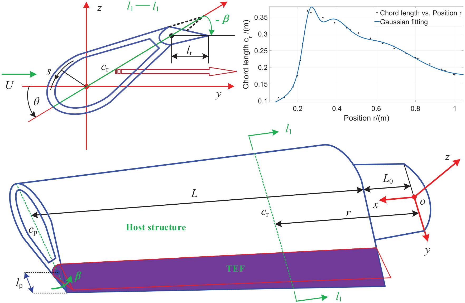
The TEF-based composite blade using CAS configuration.
The structural parameters of the blade, the composite properties and the elastic parameters are as follows: the practical angle of
The composite host structure considered is designed by a series of assumptions: (a) The blade is much stiffer in
The purpose in the present study is to investigate the control effects of


where
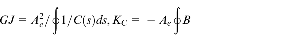
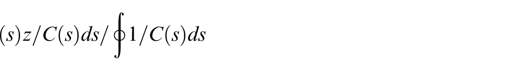
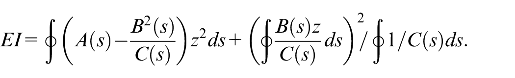
The stiffness coefficients mentioned above can be obtained by calculation of reduced axial stiffness A(s), coupling stiffness B(s), shear stiffness C(s), and sectional area
In addition, a new proposed quasi-steady aerodynamic model composed of aerodynamic Lift force
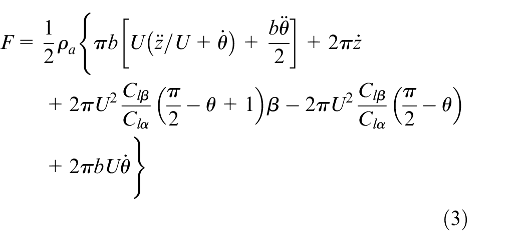
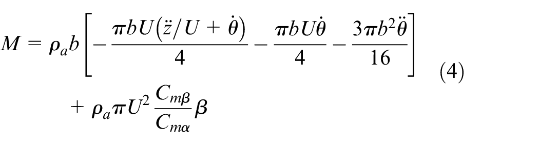
where ρa is the air density; the lift and moment coefficients per angle of attack are denoted by
Further, the aerodynamic
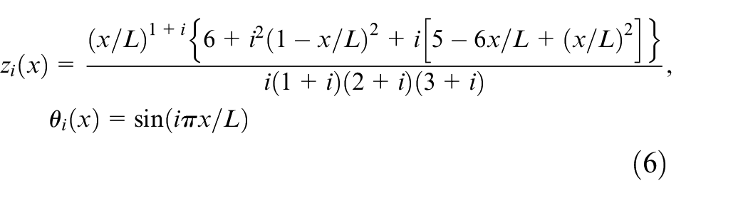
To solve the partial differential equations given by equations (1)–(2), an accurate modal method based on standard GM analysis is implemented by Hodges and Pierce. 22 It is assumed that:


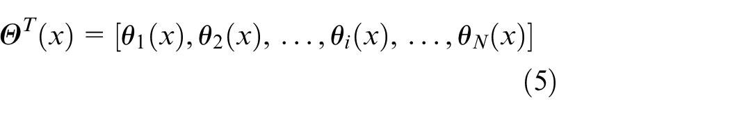
where the reserved modes,
Substitute equations (3)–(6) into equations (1)–(2), and assume
Vibration control based on LMI/RCI
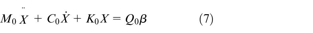
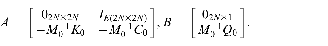
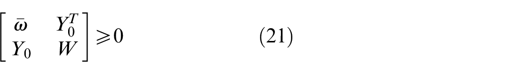
Considering the actual range of swing angles of TEF in engineering applications, as mentioned above, the TEF structure needs to be driven by LMI using strictly defined input signal. However, there are very few LMI algorithms that not only satisfy the control effects but also have restricted control inputs. The LMI/RCI algorithm based on Schur complement theorem is one of these algorithms. 16 To carry on subsequent solving, equation (7) can be transformed into the state-space, with 4N+ 4N sub-equation structures as follows:

where
Design and convergence analysis of controller
The control input signal, that is the angle
The Lyapunov function is designed as follows:

where
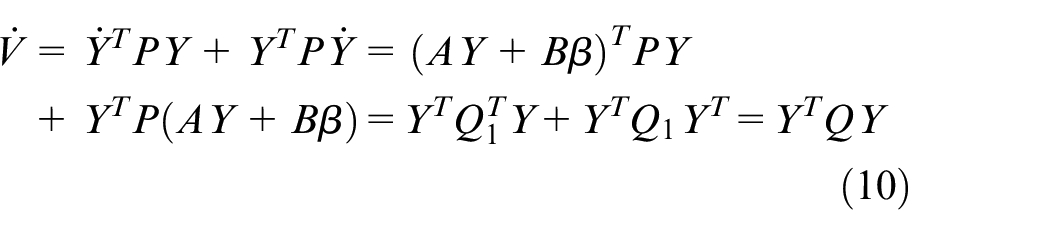
where
In order to achieve an exponential convergence, that is,

let

if
Design of LMI/RCI
Since
We might as well let
then there exists the inequation
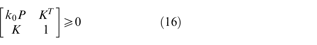
Through the above analysis, we might construct two inequalities and solve them according to Schur complement theorem.
16
The first one is

Pre-multiplication
The second inequation constructed is
Similarly, pre-multiplication and post-multiplication with
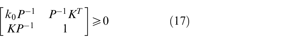
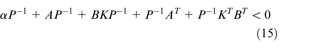
Consider equation (15) and equation (17), let

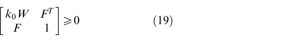
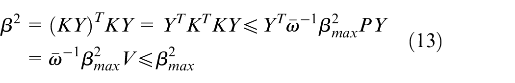
In order to further strictly limit the input signal, we add two other restriction strategies, as follows:
According to the definition of

According to
then the effective controller
Therefore, in the process of algorithm implementation, as long as we select the initial maximum value
Numerical analysis and discussion
The related parameter values of the TEF blade system, including structural parameters and external motion parameters, follow the values given in the section 2. Figure 2 shows the simulation results of uncontrolled twist
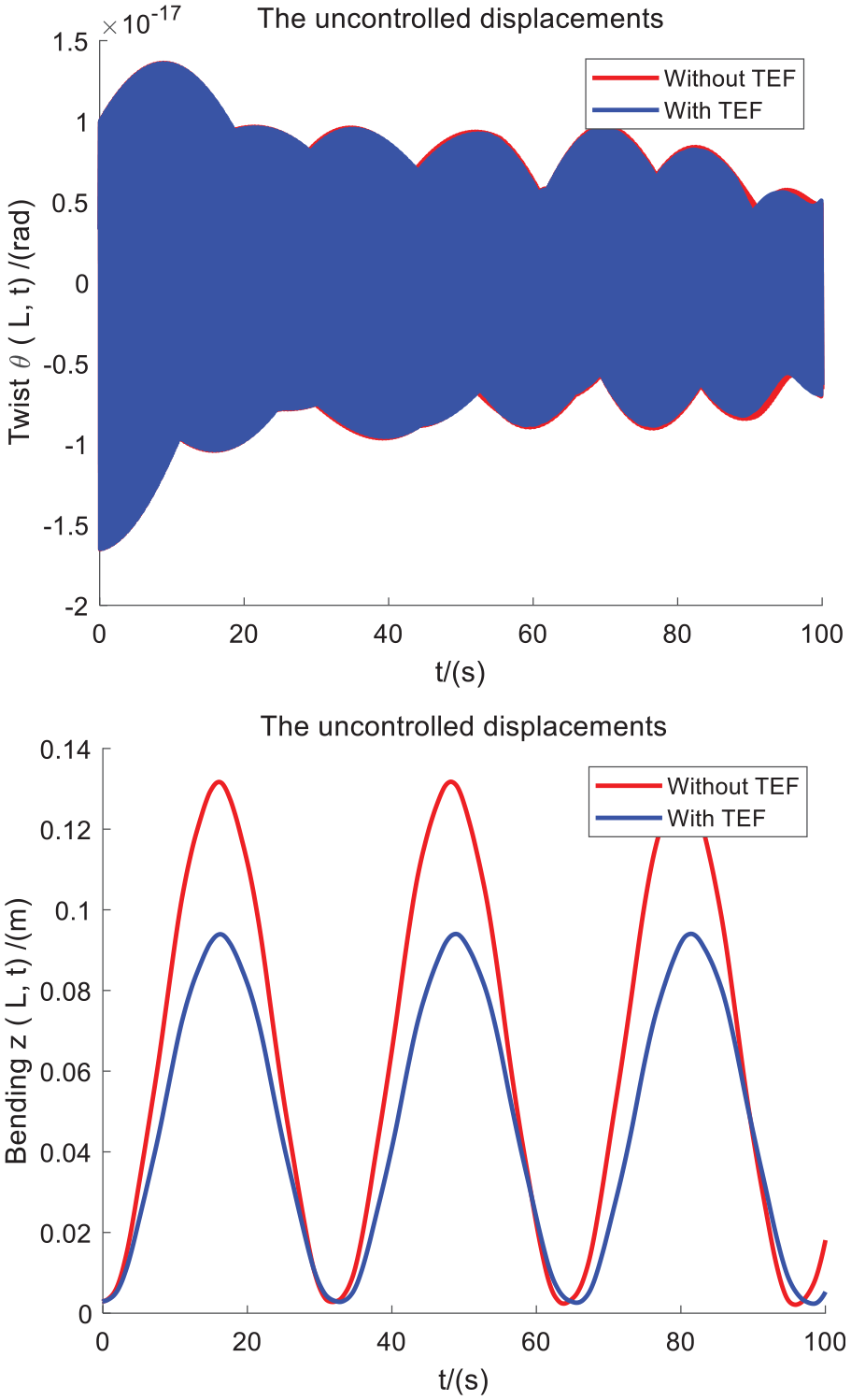
The uncontrolled displacements.
The bending displacement using TEF shows almost equal-amplitude vibration of 0.1m. It is noted that the amplitude of 0.1 m is about 1/10 of the blade length
It should be stated that the twist displacement with TEF is almost the same as that without TEF, so the influence of TEF on twist displacement can be ignored. The flap-wise displacement in the case of using TEF is obviously smaller than that in the case of no TEF. It can be seen that the influence of TEF on flap-wise displacement is important, which further illustrates the importance of using TEF to control flap-wise displacement in the present study.
Result of LMI/RCI control
To highlight the superiority of LMI/RCI algorithm driving the TEF structure, Figure 3 shows the controlled displacements(a), the controlled vibration speeds(b), and the practical control input signals
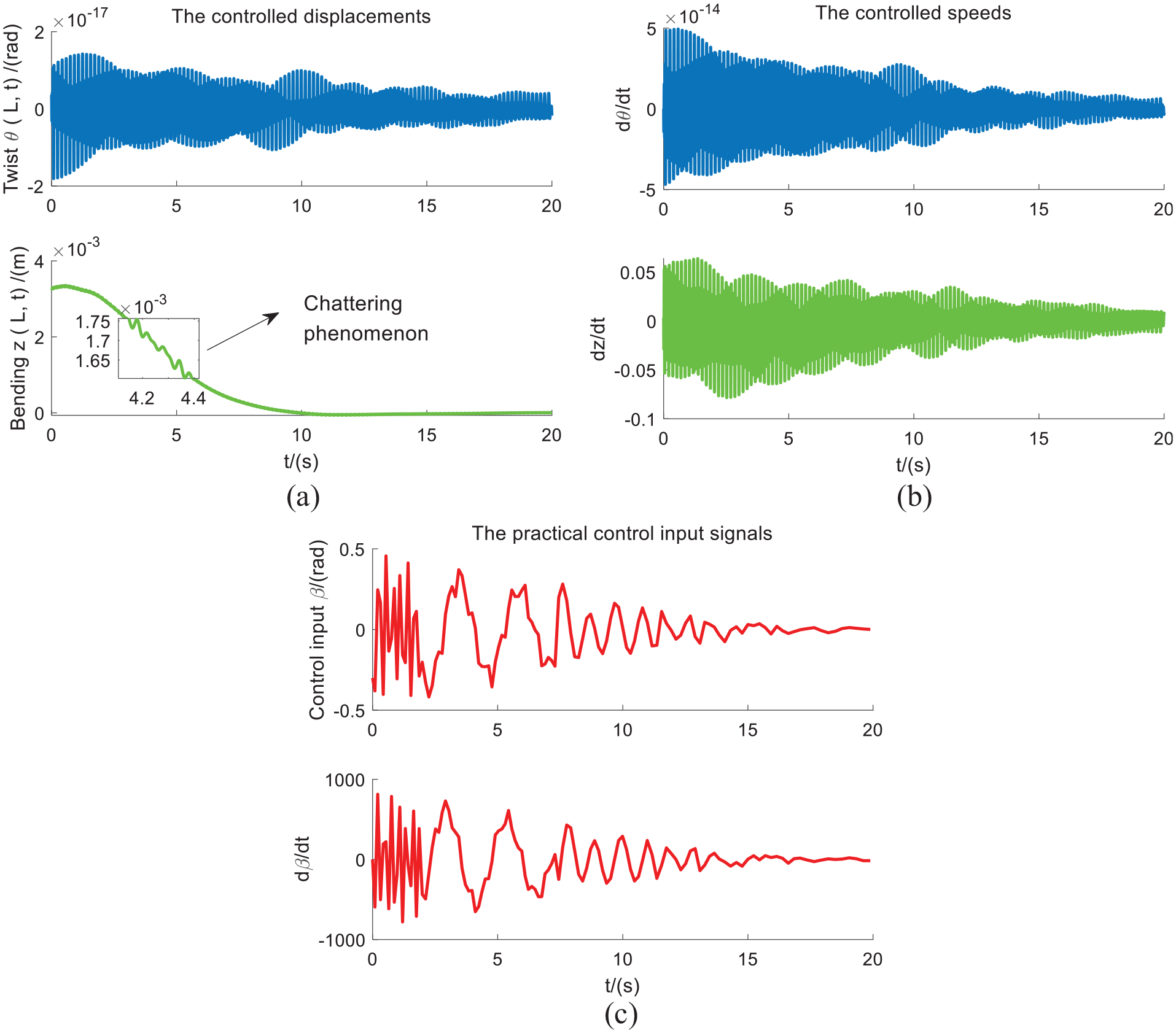
The controlled displacements (a), vibration speeds (b), and the practical control input signals
In Figure 3(a), the amplitude of the controlled bending displacement (z) is greatly reduced compared with the uncontrolled displacement (z) using TEF in Figure 2, and the fluctuation trend shows rapid attenuation, which reflects the effectiveness and superiority of the control algorithm. In Figure 3(b), the variation ranges of the vibration speeds (dz/dt) of bending motion are also small, which reflect the stability of vibration control. In addition, compared with the uncontrolled bending (z) in Figure 2, the controlled one in Figure 3(a) shows a chattering phenomenon, which is exactly the characteristics of LMI control, however, the amplitudes of the chattering fluctuation are small and do not have a destructive effect on the blade.
The signal fluctuation of the practical control input signal
Discussion of LMI/RCI control
As mentioned above, suppression for bending flutter is the central content of this study, and the limited range of control input
Case 1:
Case 2:
Case 3:
Case 4:
Case 5:
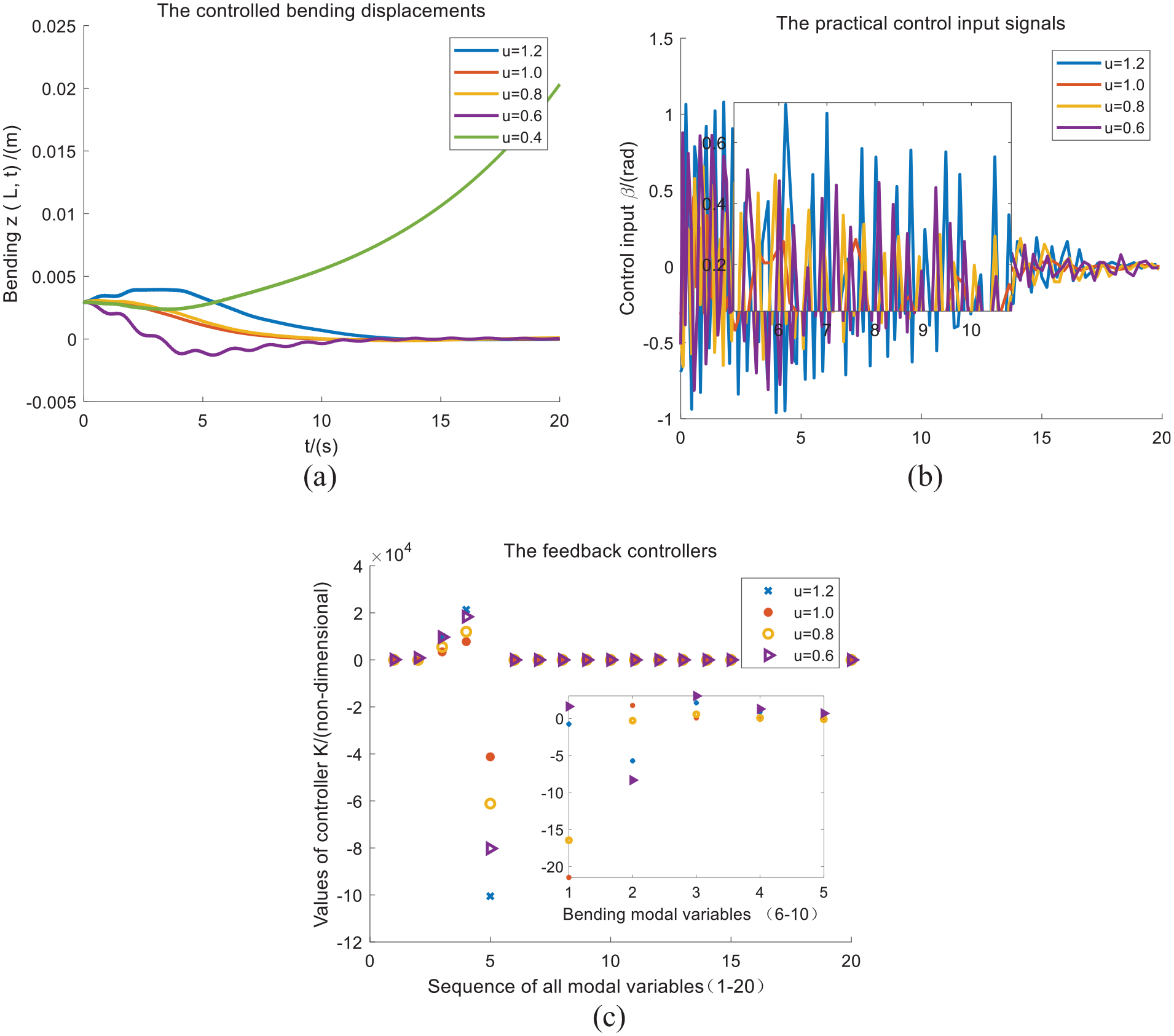
The controlled bending displacements (a), the practical control inputs (b), and the feedback controllers (c), under the conditions of different theoretical values of
From the bending displacements in Figure 4(a), it can be seen that, when the initial, theoretically restricted input is too small, for example,
Figure 4(b) shows the practical control input signals
The feedback controllers
In summary, the features of LMI/RCI control based on restricted control inputs
Validity of methodology
Validity of GM
The LMI/RCI algorithm is based on system equations of equations (7)–(8), and the discretization of partial differential equations given by equations (1)–(2) is realized by GM way, hence the effectiveness of GM needs to be validated. If the aerodynamic terms in equations (1)–(2) are ignored, then the system equations degenerate into free-vibration equations. At this time, the eigenvalues of the system equation (8) can be solved, and the characteristic frequencies can be obtained. In view of the importance of bending motion, this design only examines the eigenvalue problem of bending motion. In addition, Dancila and Armanios 19 proposed an eigenvalue calculation method for CAS-based cantilever beam, which is an accurate calculation method (CM) for frequencies of bending displacements as follows:
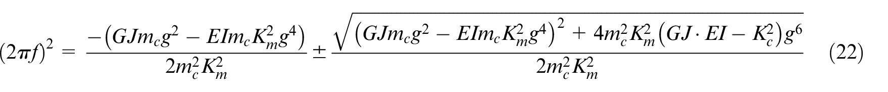
herein, parameter
Under conditions of ply-angle
Comparisions of the first three-oder frequencies
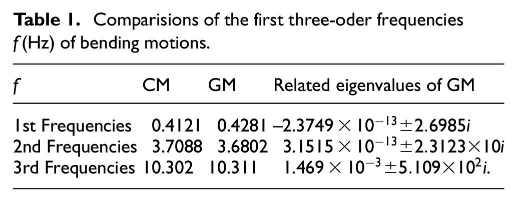
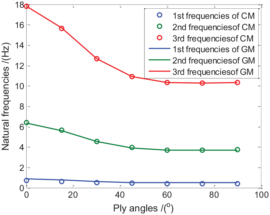
Comparisions of the first three-oder frequencies
It should be stated that, as shown in Dancila and Armanios, 19 under CAS condition, the coupling motion is only shown as the coupling state between flap-wise bending and twist, which is exactly suitable for describing the aeroelastic behavior under quasi-steady aerodynamic force, so edge-wise bending is not involved. This is exactly the reason why the frequency structure described in Dancila and Armanios 19 is used to verify the effectiveness of GM method in the present study. However, the edge-wise bending behavior should be taken into account if the stall-induced state is to be studied, then the quasi-stable aerodynamic force is no longer applicable and should be replaced by the aerodynamic force under the stall condition. 6
Validity of the LMI/RCI algorithm in the hardware implementation
The virtual simulation platform was proposed to verify the feasibility of the hardware implementation of the control algorithm. It was a simulation platform using controller-hardware-in-the-loop technology based on virtual simulation and OPC method and MATLAB/SIMULINK (MS) environment.24,25 To avoid the failure of the algorithm in the hardware implementation due to the problem of hardware memory limitation and cumulative error of calculation in the hardware just mentioned, the virtual simulation platform is used in the present study to verify the feasibility of the hardware implementation of the LMI/RCI algorithm.
In virtual simulation platform using virtual simulation and OPC method, the LMI/RCI theory runs completely in the hardware of the Siemens S7-300 CPU; the virtual simulation process of the blade system is realized completely in the MS environment in PC; WinCC software runs in MS and activates a server component named SWOU server, which communicates with S7-300 CPU by MPI Cable on the one hand and the blade system model of the OPC client in MS environment on the other. 26 The OPC toolbox module library in MS has related OPC Read-Write modules. With the help of SWOU Server, the Read-Write operation between S7-300 CPU and MS environment can be realized. The structure diagram of online control and workflow chart of SWOU communication are illustrated in Figure 6. The specific workflows of SWOU Server are as follows:
Build and activate SWOU Server in WinCC and setup program interface DCOM;
Create OPC data areas in WinCC to access client objects; the address of data areas should be consistent with those of variable areas in S7-300 CPU;
Add objects and groups in OPC client in MS;
Mapping data areas in SWOU server to both Simulink workspace and memories of S7-300 CPU;
Start the virtual simulation in the MS, observe the running state of CPU, and observe the simulation results in the WinCC interface.
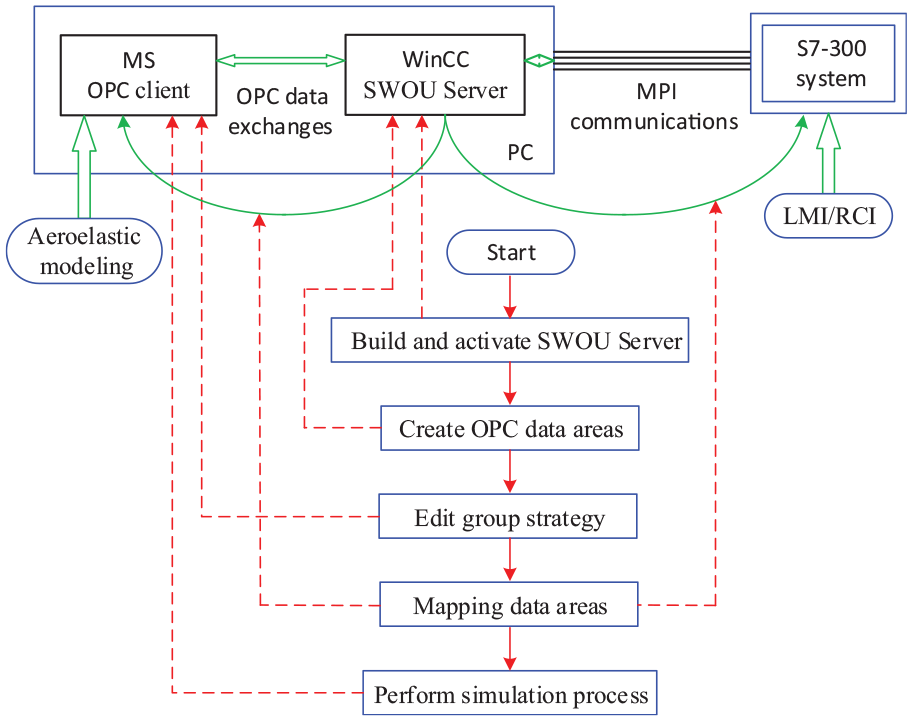
The structure diagram of online control and workflow chart of SWOU communication.
The signals of the controlled bending displacement
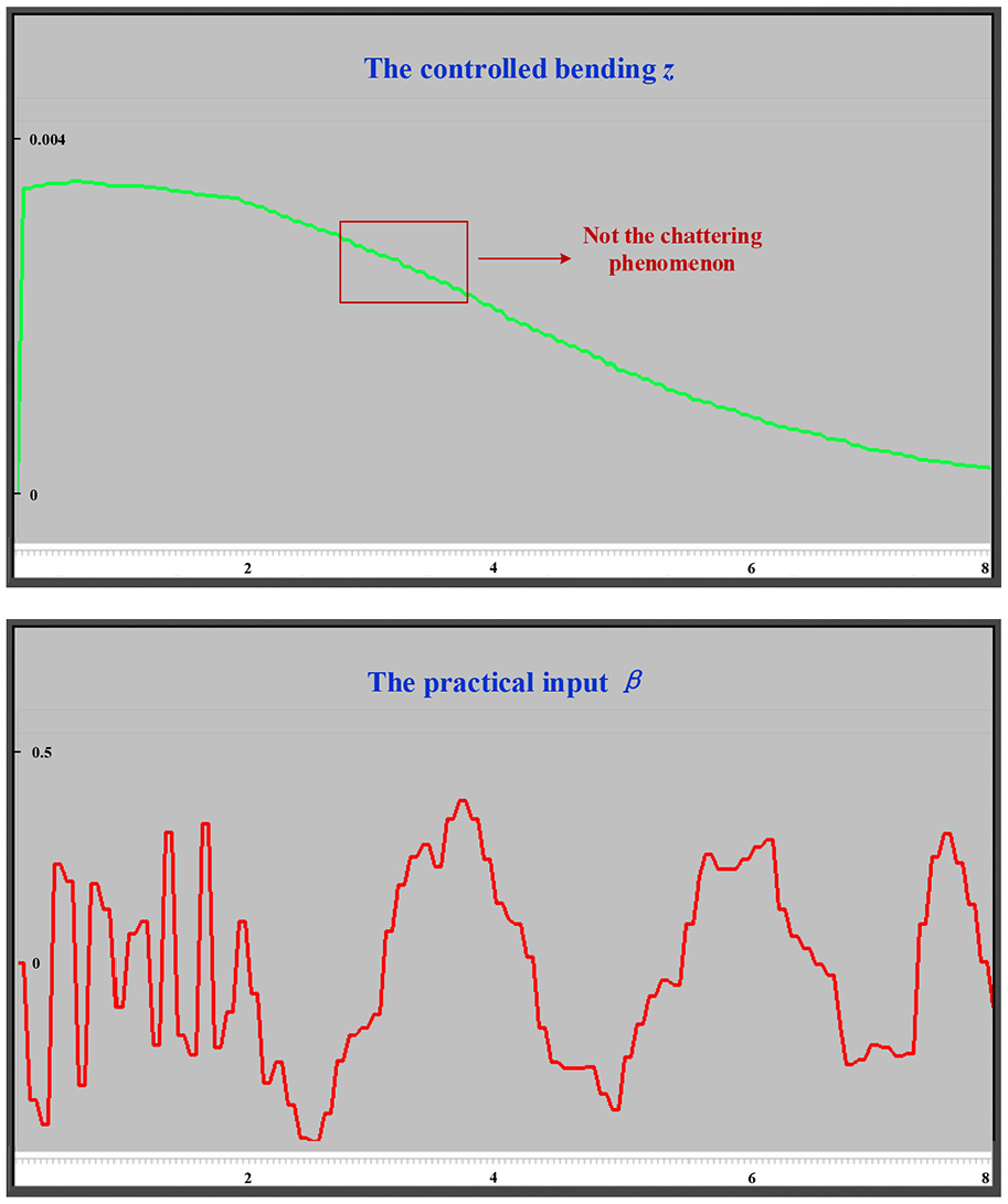
The controlled bending displacement
The WinCC interface shows the processes of dynamic fluctuations of two signals. Compared with the controlled bending displacement
It should be stated that because of the difference between the actual sampling time of the platform hardware and the theoretical sampling time of the numerical simulation process, the former has the limitation of sampling interval, so the fluctuations of the curves in Figure 7 are relatively smooth (Note that the chattering phenomenon is not visible due to excessive sampling intervals for hardware), and there are no sharp changes of the peak-values of the curve of the practical input
Conclusions
In this study, vibration and control of BTC blade based on TEF using restricted control input are investigated. Some concluding remarks can be drawn from the results:
The CAS-based composite blade is embedded in span-wise TEF structure driven by quasi-steady aerodynamic forces. The blade exhibits the BTC displacements, with the solution of its aeroelastic system investigated using standard GM theory.
Vibration control is investigated based on LMI/RCI algorithm. Flutter suppression of BTC displacements and the angle of TEF, that is, the practical control input, are illustrated. Different preset input signals, that is, the theoretical TEF angles, are introduced into LMI/RCI algorithm to realize flutter suppression for bending displacements, with practical control inputs
The theoretically restricted input signals are used in LMI/RCI algorithm to drive TEF to explore the scope of the feasibility of the practical TEF angles. The theoretical input signal,
Footnotes
Appendix
Declaration of conflicting interests
The author(s) declared no potential conflicts of interest with respect to the research, authorship, and/or publication of this article.
Funding
The author(s) disclosed receipt of the following financial support for the research, authorship, and/or publication of this article: This work is supported by the National Natural Science Foundation of China (Grant no. 51675315).