
Abstract
An integrated fault tolerant controller is proposed for vehicle chassis system. Based on the coupled characteristics of vertical and lateral system, the fault tolerant controller mainly concentrates on the cooperative control of controllable suspension and lateral system with external disturbances and actuator faults. A nine-DOF coupled model is developed for fault reconstruction and accurate control. Firstly, a fault reconstruction mechanism based on sliding mode is introduced; when the sliding mode achieves, actuator fault signals can be observed exactly through selecting appropriate gain matrix and equivalent output injection term. Secondly, an active suspension controller, a roll moment controller and a stability controller is developed respectively; the integrated control strategy is applied to the system under different driving conditions: when the car is traveling straightly, the main purpose of the integrated strategy is to improve the vertical performance; the lateral controller including roll moment control and stability control will be triggered when there is a steering angle input. Simulations experiments verify the performance enhancement and stability of the proposed controller under three different driving conditions.
Keywords
Introduction
The performances of vehicles are influenced by the chassis system. Active control technology can effectively improve the riding comfort, maneuvering stability and safety characteristic of vehicles by using a variety of advanced control algorithms, such as controllable suspension system,1,2 steering control systems,3,4 electronic stability program, 5 etc. However, most of the individual control systems were designed under special operating conditions, simple superposition of these single control systems may result in degraded or even unstable performance. To avoid mutual interference between sub-control systems, the integrated chassis control technology has been widely used.
The key issues of the vehicle chassis system are the coupling characteristics of subsystems, the interaction between tires and the road surface, and establishment of the nonlinearly coupled dynamic models. 6 Based on the coupled mechanisms, some control systems containing different subsystems have been proposed. Poussot-Vassal et al. 7 designed a gain scheduled vehicle stability controller including steering and braking actuators, and the effectiveness of the controller was verified under critical driving situations. Yang et al. 8 presented an optimal guaranteed cost controller to improve the stability and tracking performance of the chassis system. Mousavinejad et al. 9 designed an integrated AFS and DYC control algorithm, so as to improve transient response of controllers. In view of the interaction between vertical and lateral dynamic of vehicles, Fergani et al. 10 investigated a linear parameter varying and flatness based global chassis control of vehicles to achieve collaborative control of suspension and steering/braking systems. Rodrigue Tchamna et al. 11 also investigated a global control method, which combines the electronic stability control and active suspension to get superior performance of vehicles during cornering. Although the integrated control mechanism combined with multiple subsystems can achieve better performance, the number of sensors and actuators has also increased, and the structure has become increasingly complex, which may increase the probability of sensor and actuator faults. 12 To avoid these shortcomings, fault tolerant mechanism is needed to handle system failures and maintain expected properties.
Passive fault tolerant method has been extensively used for automobile systems. Moradi and Fekih13,14 developed a passive fault tolerant mechanism to suppress the influence of actuator faults. A robust fault tolerant method was presented by Ali et al. 15 to process the engine air path actuator faults. An adaptive fault tolerant compensation control and output feedback finite-time control of active suspension systems were designed by Pan and Sun16,17 for stabilizing the perturbed vehicle active suspension system to improve the suspension performance. However, the robustness based passive fault tolerant control will reduce the effect of failures at the cost of system performance and cannot detect the location of faults. Based on the fault diagnosis, active fault tolerant method can reconfigure the control system through estimating the current fault. 18 Many active fault tolerant controllers have been applied to automobile systems. An Unknown Input Observer approach was used by Alain Yetendje et al. 19 to detect and identify actuator fault of active suspension systems. On the basis of fault detection and diagnosis, the robust linear parameter variable control method was investigated by Peter Gáspár et al. 20 to control the active suspension of heavy vehicles containing actuator faults. A fault-based fault tolerant feedback control was utilized by Oudghiri et al. 21 to compensate the faults and reduce the impact of faults on the lateral stability of vehicles. The previous works on integrated chassis control such as the centralized integrated controller,7,8,10 the characteristics of each subsystem and the coupling relationship between the subsystems were not fully considered. In this paper, a hierarchical integrated controller is developed, among which suitable controllers for each subsystem are designed, and an integrated control strategy is utilized to coordinate the vertical and lateral dynamics. In the previous works on fault tolerant control for vehicle chassis systems, passive fault tolerant control or active fault tolerant control mainly concentrate on individual chassis system such as active suspension system. However, in this study, we consider the fault tolerant control for integrated vehicle model. Besides, the sliding mode-based fault observer can also observe the unmeasured states simultaneously. The necessity of providing an integrated fault tolerant control, in the presence of external road inputs and actuator faults while ensuring stability and performance of the control system, forms the focus of the work proposed in this paper.
In this study, a nine-DOF integrated model is established, and actuator faults are taken into account. A sliding model observer is employed to estimate fault signals and system states, and a hierarchical integrated mechanism is designed to improve vehicle chassis properties. The main innovations are:
(1) A sliding mode fault observer is employed for actuator fault signal and state estimation of the chassis model.
(2) A hierarchical mechanism is designed for the chassis model to achieve performance improvement of the integrated vertical and lateral model.
Vehicle dynamic model
For controller design purpose, a suspension model and a four wheels lateral model are utilized to describe the coupled dynamics of the vehicle.
Vertical model
A 7-DOF suspension model with heave, pitch and roll motions is used in this paper, 22 as shown in Figure 1.
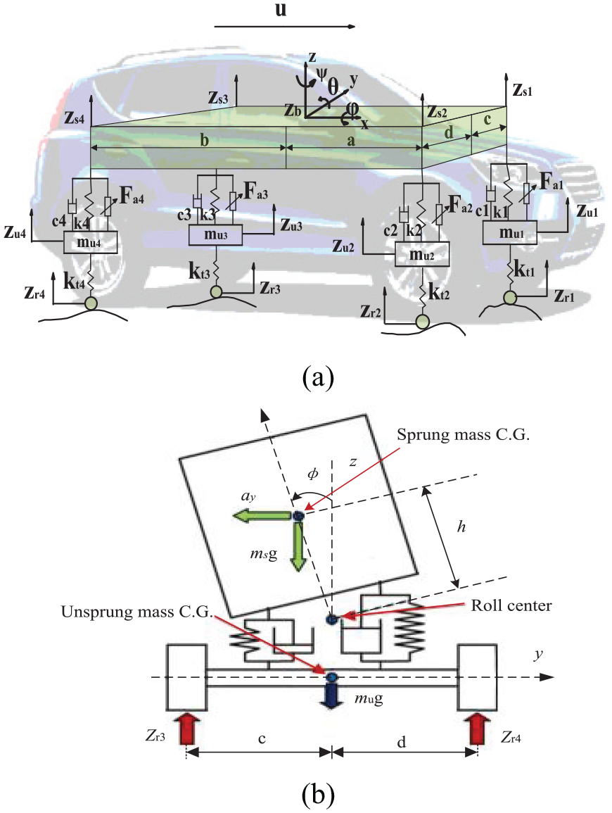
Suspension model: (a) vertical model and (b) roll motion.
The terms
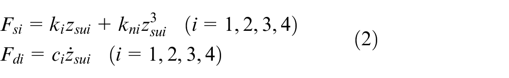
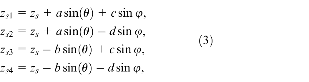
The suspension deflections are expressed as

The spring and damping forces are
According to small angle assumption, the following approximate equation can be got
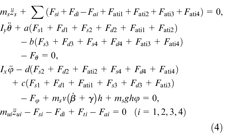
The vehicle vertical model with sprung and unsprung mass dynamics can be given as 23
The anti-sway bar forces are as
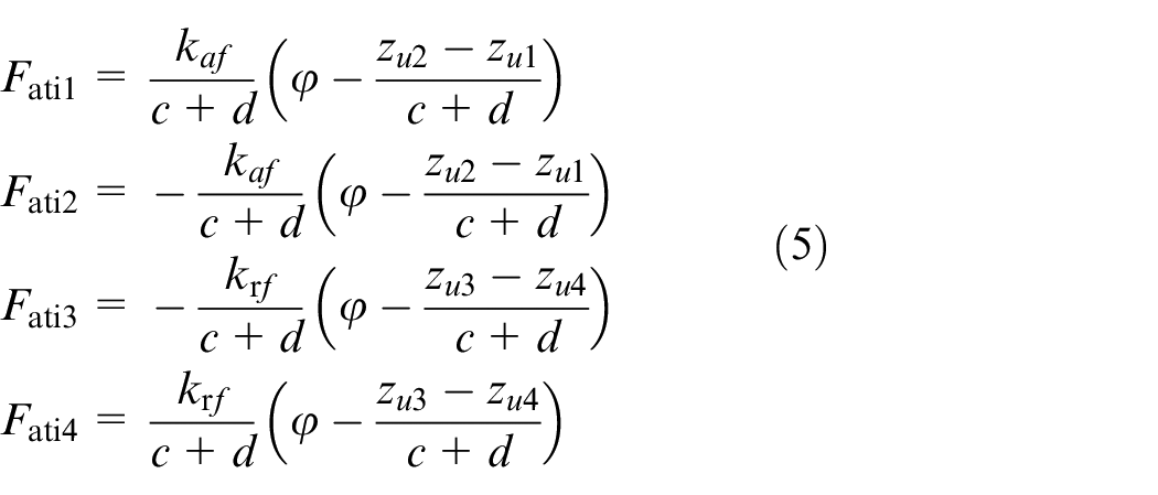
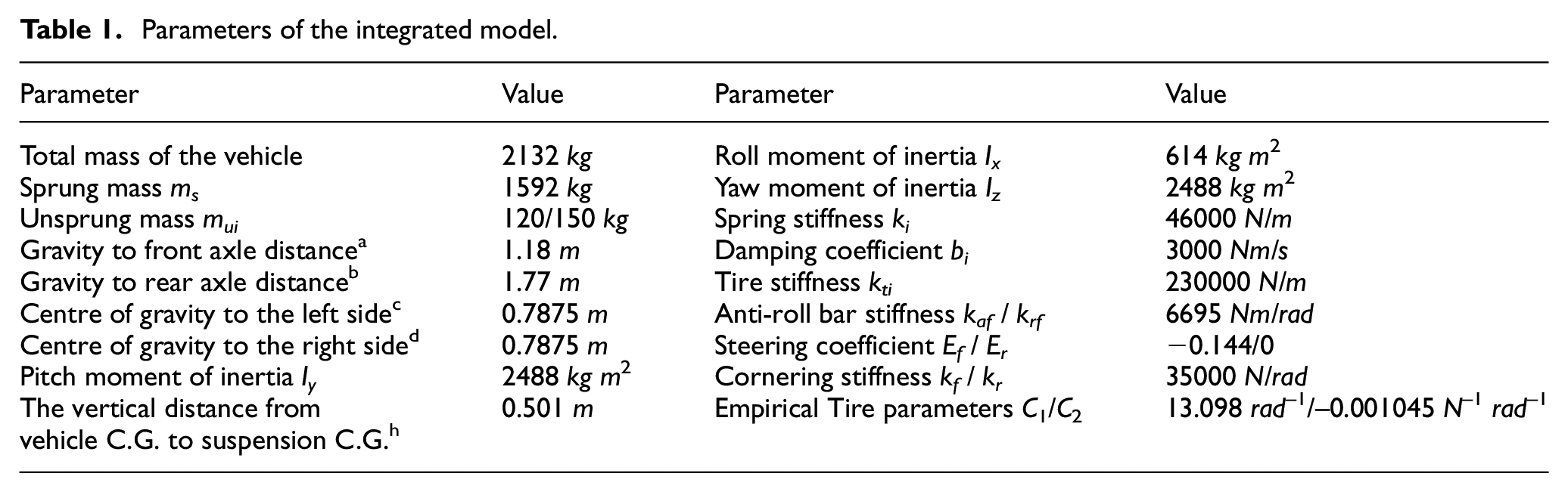
The meanings of specific symbols are shown in Table 1.
Parameters of the integrated model.
Lateral model
Vehicle lateral system shown in Figure 2 is utilized to develop the roll moment distribution controller and the stability controller. The lateral motion can be expressed as 24


where
The expected yaw rate is as 25
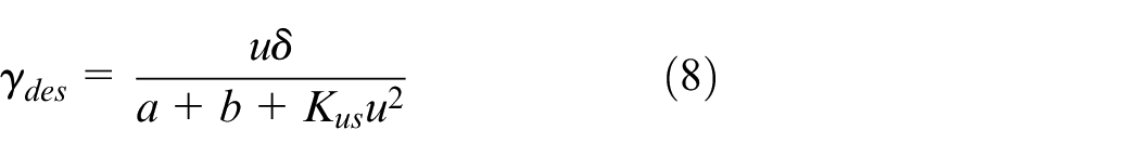
where Kus is the understeer coefficient and in the neutral steering, and
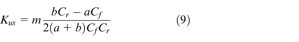
among which
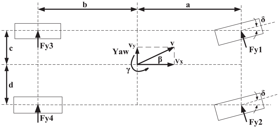
Vehicle lateral model.
Tire model
Although the tire lateral force is well defined as a first order approximation, the resulting change in lateral force does not consider the change of normal force. So it is necessary to employ side slip angle and normal force to generate tire lateral force. Besides, to obtain the impact of roll moment distribution, the higher order term with normal force is included. Then the lateral force developed by each tire can be given by 26 :

where
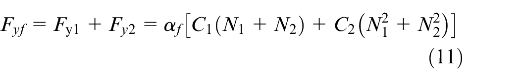
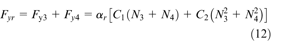
among which
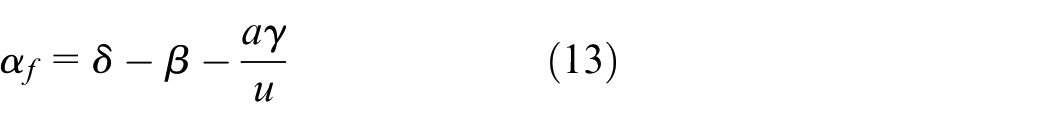
where
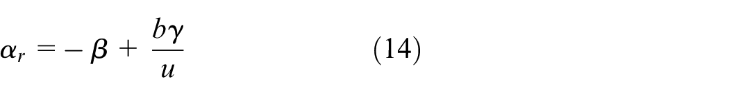
When the vehicle turns, the weight of the sprung mass shifts from the inner wheel to the outer wheel, and the transferred weight is related to sprung mass, yaw rate, speed and the sprung mass center position. The transferred weight should be reacted with the suspension roll motion. Differences of the front and rear suspension characteristics would produce the roll moment distribution. By using the active control techniques, a distribution coefficient can be assigned
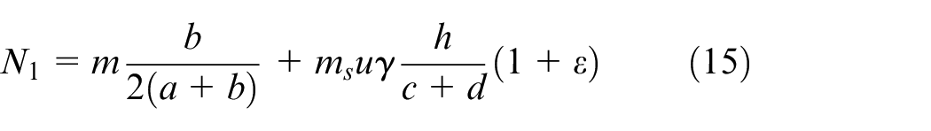
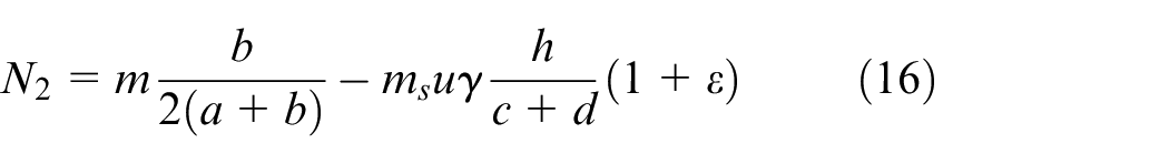
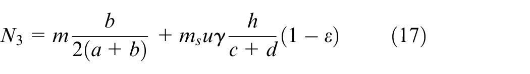
where
Fault observer design
Sliding mode observer
The state variable of the integrated model is given as
Define the road input and front wheel angle as the external interferences input, the interference variables are represented as

The control variables of the integrated system include the additional yaw moment generated by the electronic stability control system and the active suspension force, which can be written as

The system measurement outputs are selected as

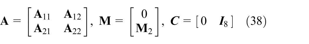
Then, the system model can be written as
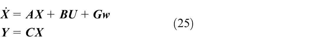
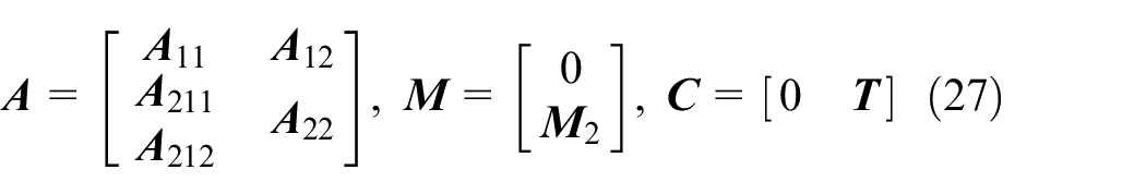
Among which
Suppose that rank
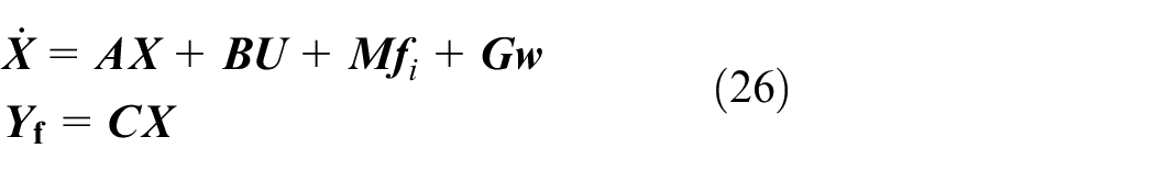
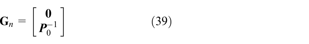
Considering equation (26), the observer that will be considered in the paper can be written as 29
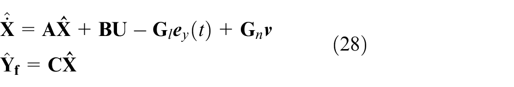

among which
where
where


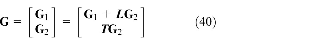
By introducing a new coordinate transformation
where
The disturbance matrix has the form
and the Lyapunov matrix can be written as
The estimation error in new coordinate can be partitioned as
then the sliding mode will occur in finite time.
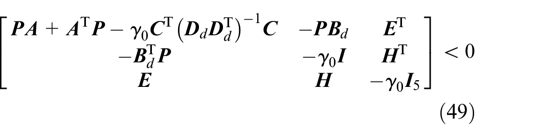
Robust fault observer
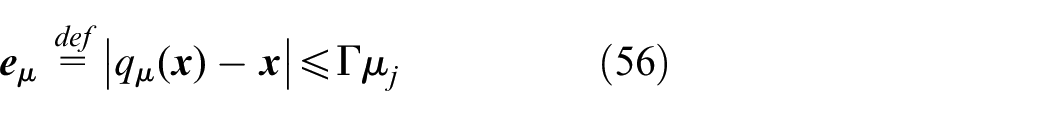
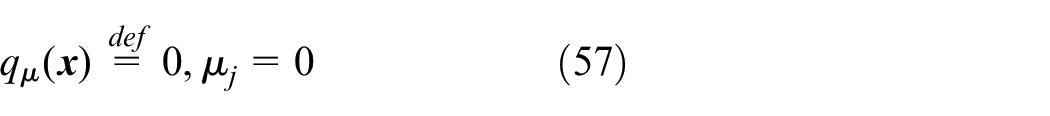
To estimate fault signals exactly in the presence of interferences, assume that sliding motion in
where
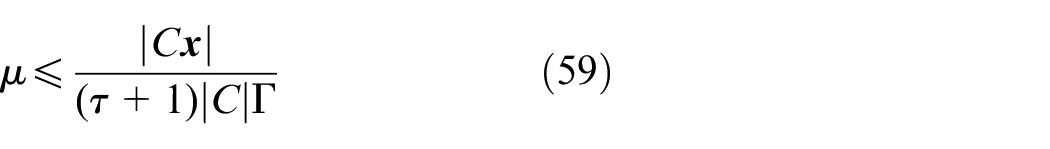
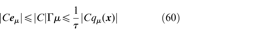
Then the objective is to keep
The Lyapunov matrix satisfies
and
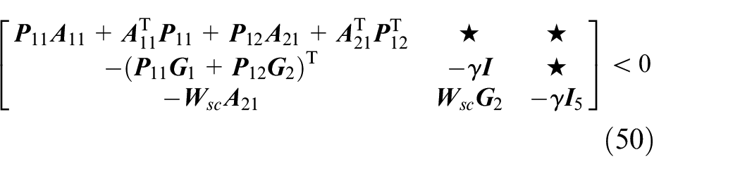
The stars in inequality represent the matrix is symmetric. If the gain matrices of the observer are selected as
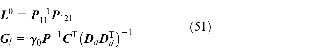
then
Stand-alone controller design
Suspension controller design
To improve system stability and achieve desirable suspension performance, a quantization based sliding mode controller is utilized. In the designed control system, the controller is approximately considered as a continuous system. The control diagram is shown in Figure 3. The switch block in Figure 3 refers to the conversion relationship between the input voltage and output force of the electro-hydraulic actuator.
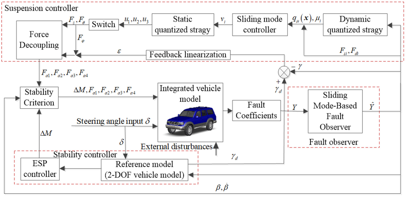
Diagram block of the proposed controller.
Quantization can be seen as a process of encoding. When analog signal is converted to digital signal, the processor maps it to a finite precision value according to a certain coding mode. Quantization control theory includes control problems based on static quantizer and dynamic quantizer, among which the dynamic quantizer expands the quantization range by adjusting the quantization level to achieve asymptotic stability of the system. 31 This section mainly concentrates on the connection channel between the suspension model and the controller; both static quantizer and dynamic quantizer are used, and traditional sliding mode controller is also adopted. The quantization system is shown in Figure 4.
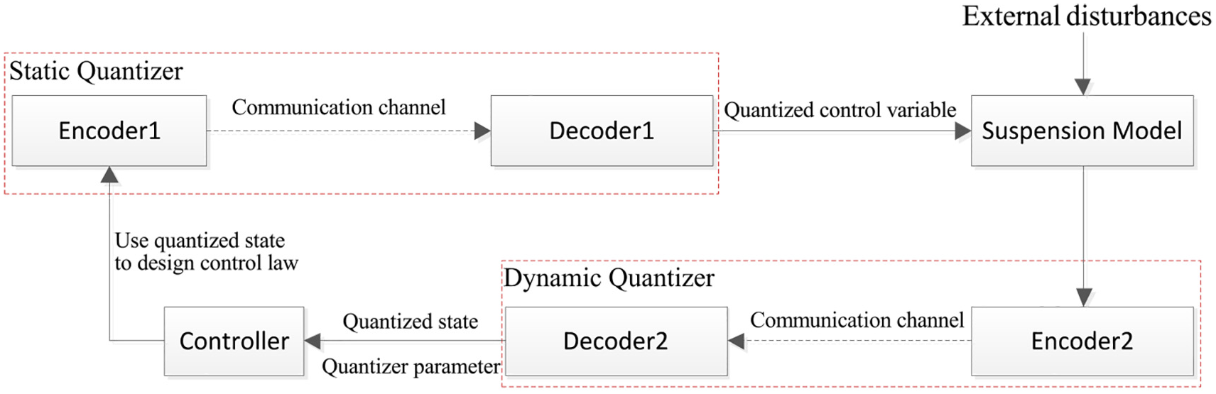
Flow chart of the quantization system.
Assuming the suspension states and road profiles are bounded. Selecting state variables as

The suspension system model can be expressed as
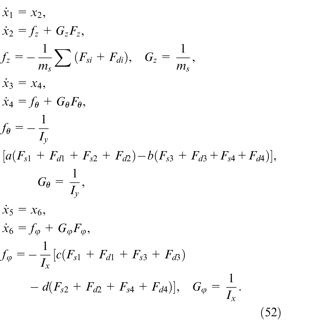
the above functions are rewritten as 32

where
As shown in Figure 4, a static quantizer
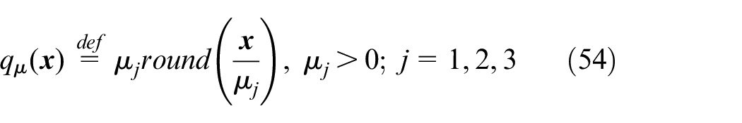
The uniform quantization error is
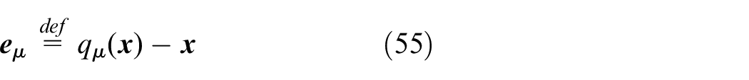
then
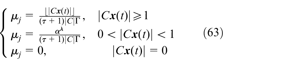
With respect to dynamic quantizer, a special quantization parameter
Defined the sliding surface

where C is a given vector to ensure the system has stable eigenvalues, and
then the following inequation can be obtained
By considering the uplink and down channel quantize, the following control law can be designed 33
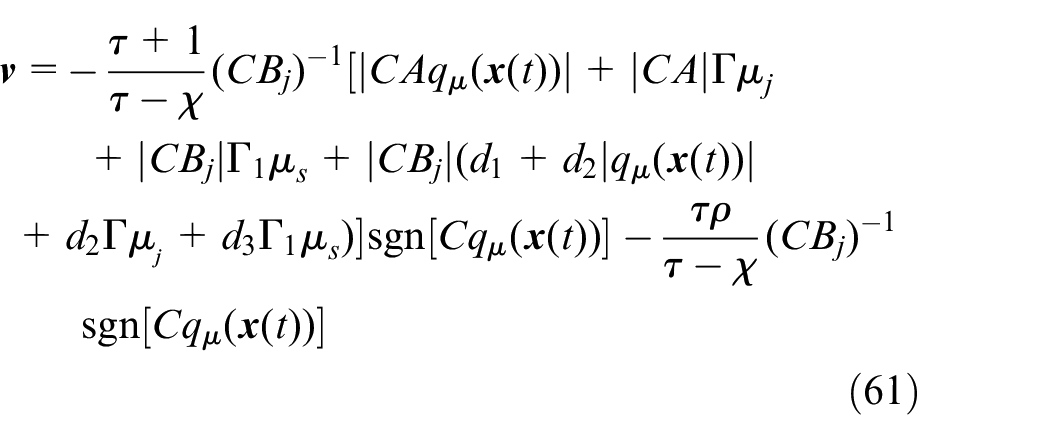

where
A simple and efficient adjustment law is as follows 34
where
Roll moment controller
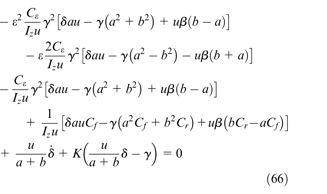
In order to obtain favorable handling characteristics in the stability region, the appropriate roll moment distribution coefficient
where when in the stability region,

then the tracking error of the yaw rate will converge to zero, and system is asymptotically stable. Introducing the notation
By solving the above equation, the roll moment distribution coefficient
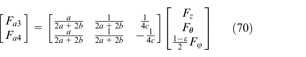
As the distances between left and right suspensions to the vehicle centerline is equal, the force transformations of active suspension can be written as
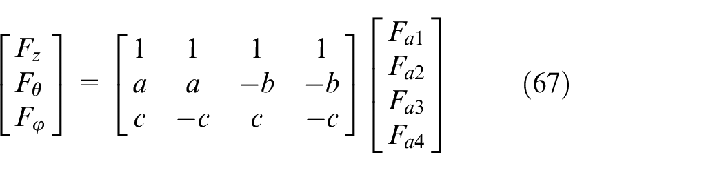
where
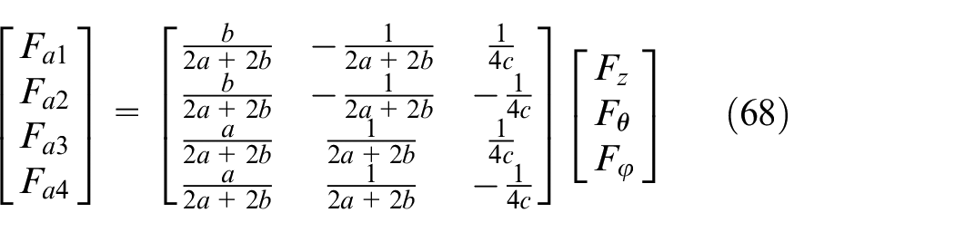
The active forces of front and rear axles are generated by the active suspensions, and can be given as
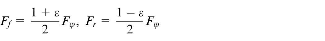
The equations can then be given as
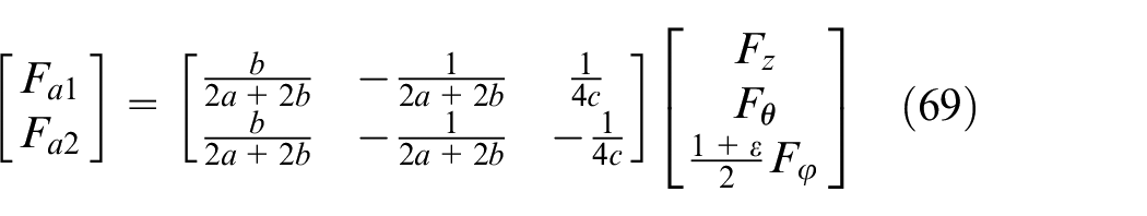
Control of sprung mass motions is changed into control the four subsystems by utilizing the decoupling calculation.
ESP controller design
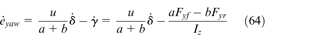
The ESP controller improves the lateral dynamics through generating corrective yaw moment. A terminal sliding mode control 36 is utilized for the ESP. According to equation (7), following equation can be got
Where

Define the sliding surface as

among which,
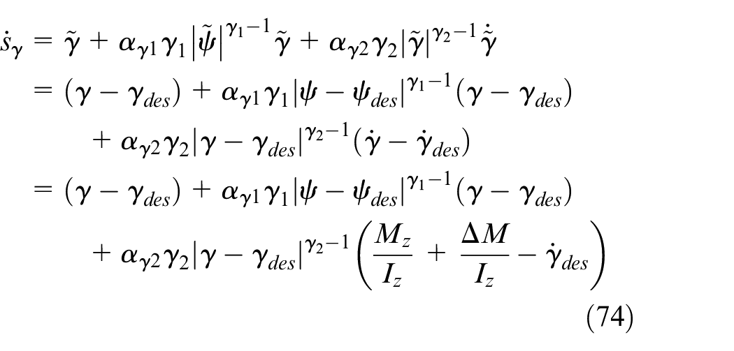
The control law of the ESP controller is formulated as
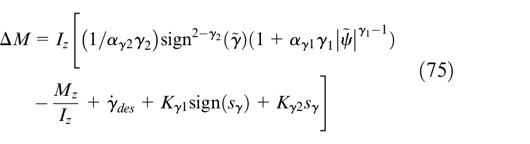
where

Define the Lyapunov function as
the time derivative of (76) is as
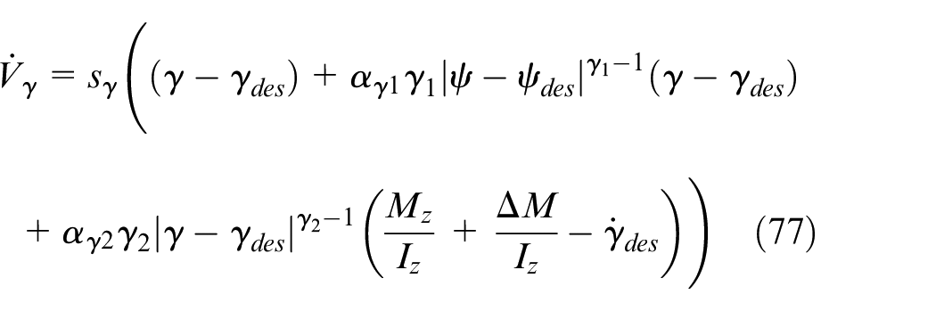
By implementing the control law (75) into (77) can obtain
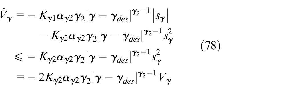
For
where
Integrated control strategy
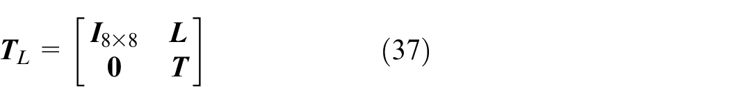
When the car travels straightly, the active suspension controller generates active control force to minimizing sprung mass motion; the roll moment controller and ESP controller do not work. As the brake-based ESP controller is not suitable for the vehicle in the stable area for the ESP controller directly affects the longitudinal motion of the vehicle. When there is a steering angle input, coordination of roll moment controller and ESP controller determines which controller is used. The boundary of the phase plane is defined as 37

In the stability area, the roll moment controller forces the yaw rate to track desired yaw rate through controlling lateral tire forces. When the system excessed the stable lines, ESP controller affords additional yaw moment to keep the car running in stability region through the differential braking system. The switching between roll moment controller and ESP controller can be expressed as

where
Simulation results
The control goal of the designed controller is to improve the chassis characteristics. In this section, the effect of the fault tolerant mechanism is validated through three different 3operating conditions. The front wheel inputs are shown in Figure 5, and the external road disturbances of four wheels are given in Figure 6. The simulation parameters are listed in Table 1.
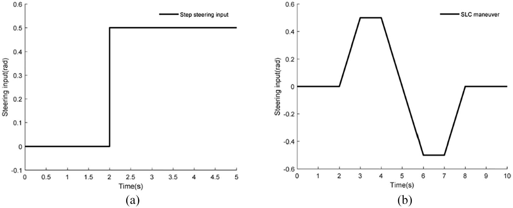
Front wheel inputs: (a) step steering input and (b) SLC steering input.
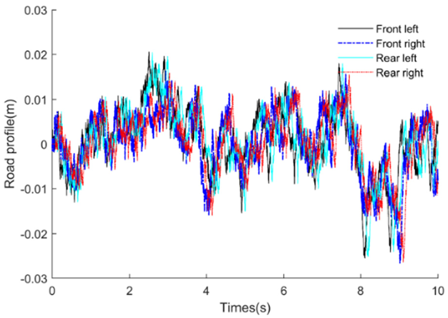
Four-wheel road disturbances.
Step steering input
The step steering input plotted in Figure 5(a) is considered in this section, and the vehicle travels at a speed of 60 km/h.
The observed results under step steering are given in Figure 7(a) to (d). The figures show that the designed observer can track the system states exactly.
Observations under step input: (a) sprung mass pitch velocity, (b) sprung mass roll velocity, (c) sprung mass vertical velocities, and (d) unsprung mass velocities.
The responses of the nominal model to the controller are given in Figure 8(a) to (e). Figure 8(a) indicates that the controller can suppress the sprung mass motion when there is no steering input, and the vibration performance of the sprung mass has been effectively improved; when there is a step steering input, the suspension performance is degraded. When there is steering angle input, the suspension and tire deflections are decreased simultaneously, as shown in Figure 8(b) and (c). Figure 8(d) and (e) indicate that during step steering, the yaw rate and lateral acceleration are reduced significantly with the integrated controller. The results are in line with the design goals.
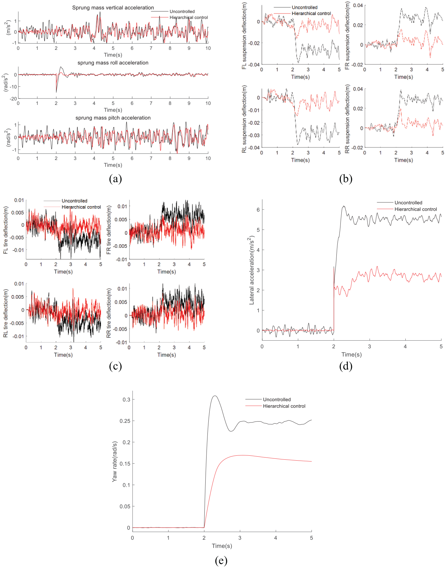
Control results under step input: (a) sprung mass accelerations, (b) suspension deflections, (c) tire deflections, (d) lateral acceleration, and (e) yaw rate.
SLC steering input
This section mainly discusses the control results of the fault tolerant controller under SLC steering input condition.
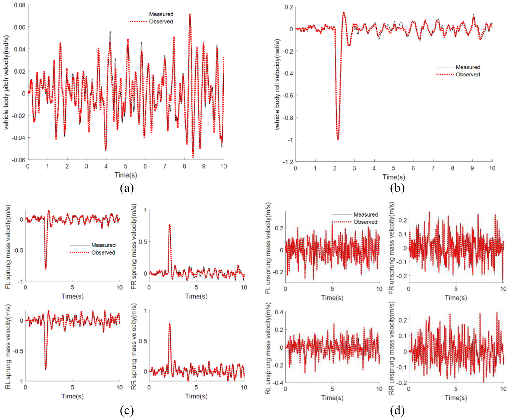
Figure 9(a) to (d) shows the observed results of unmeasured states under SLC steering input. The results show that the designed method can follow system states exactly.
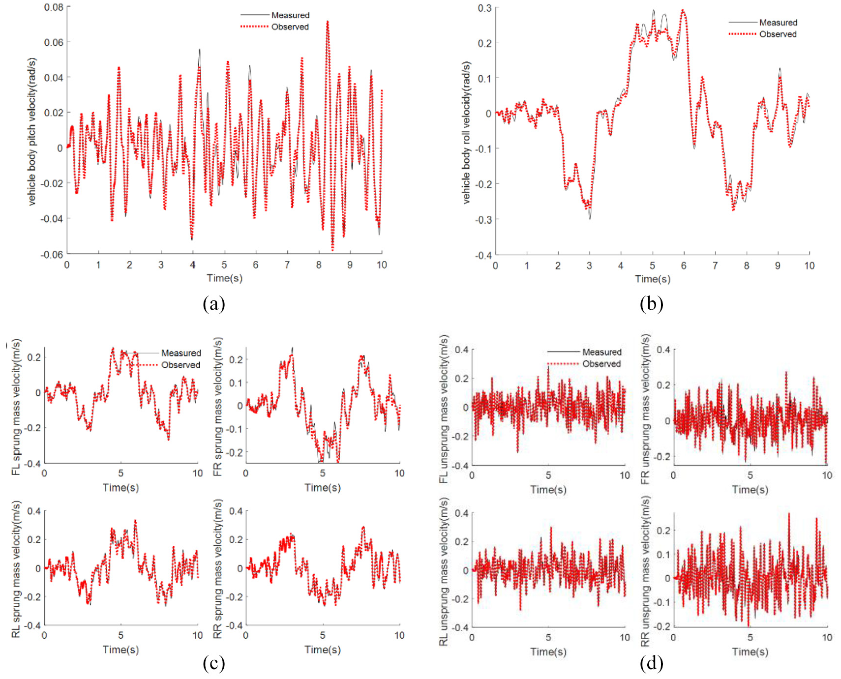
Observations under SLC input: (a) sprung mass pitch velocity, (b) sprung mass roll velocity, (c) sprung mass vertical velocities, and (d) unsprung mass velocities.
The time responses of the vertical and lateral dynamics to the integrated controller are shown in Figure 10(a) to (e). Figure 10(a) shows that the vibration performance improves significantly when there is no steering input, and the performance closes to the passive system with steering input. Obviously, the suspension and tire deflections in Figure 10(b) and (c) are almost consistent with no steering input. The lateral dynamics are given in Figure 10(d) and (e), and the lateral performance has been improved greatly under the SLC input.
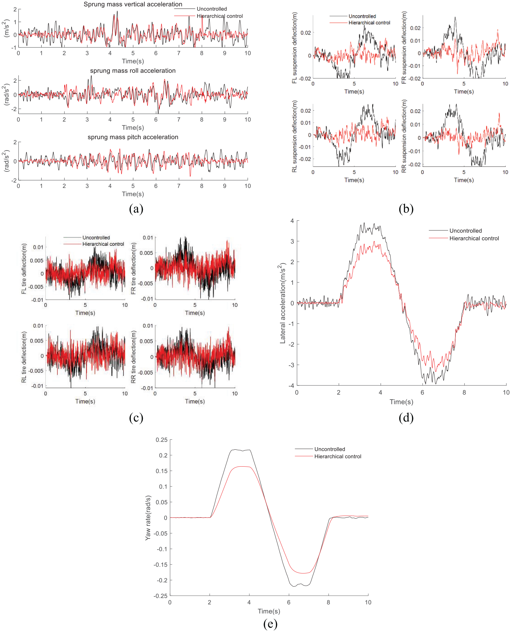
Control results under SLC input: (a) sprung mass accelerations, (b) suspension deflections, (c) tire deflections, (d) lateral acceleration, and (e) yaw rate.
Actuator fault
Loss of actuator effectiveness is discussed in this section. Assume that there is a virtual actuator that produces a yaw moment, so the actuator fault can be taken into account. The failure of four suspension actuators and one DYC actuator is analyzed here, and the considered faults are defined as follows:
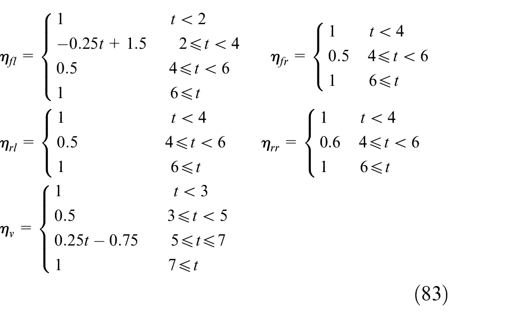
The simulation is carried out under a step input. The real fault signals and estimated fault signals of active suspension and DYC actuators are given in Figure 11(a) to (e). The estimation results indicate that the designed observer can reconstruct actuator fault signals exactly when the actuator faults occur, and the estimated values of the actuators are basically consistent with the real values.
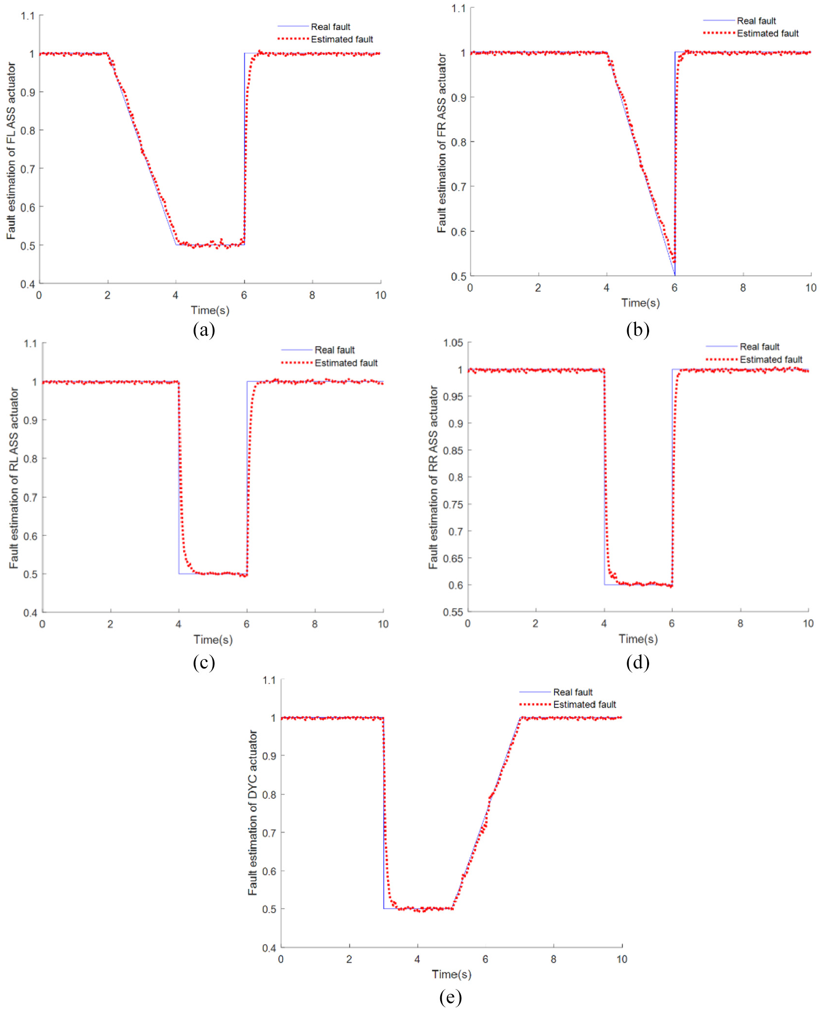
Actuator faults and estimations: (a) FL ASS actuator fault, (b) FR ASS actuator fault, (c) RL ASS actuator fault, (d) RR ASS actuator fault, and (e) DYC actuator fault.
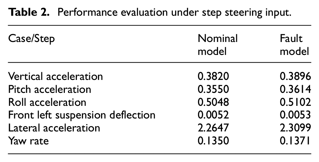
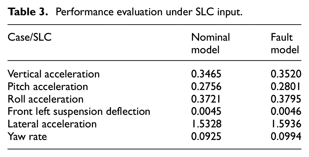
To evaluate the control performance with actuator faults, the RMS values under step steering and SLC input are presented in Tables 2 and 3, respectively. It can be deduced from tables that the proposed active fault tolerant controller provides efficient performance under fault conditions.
Performance evaluation under step steering input.
Performance evaluation under SLC input.
Comparisons between
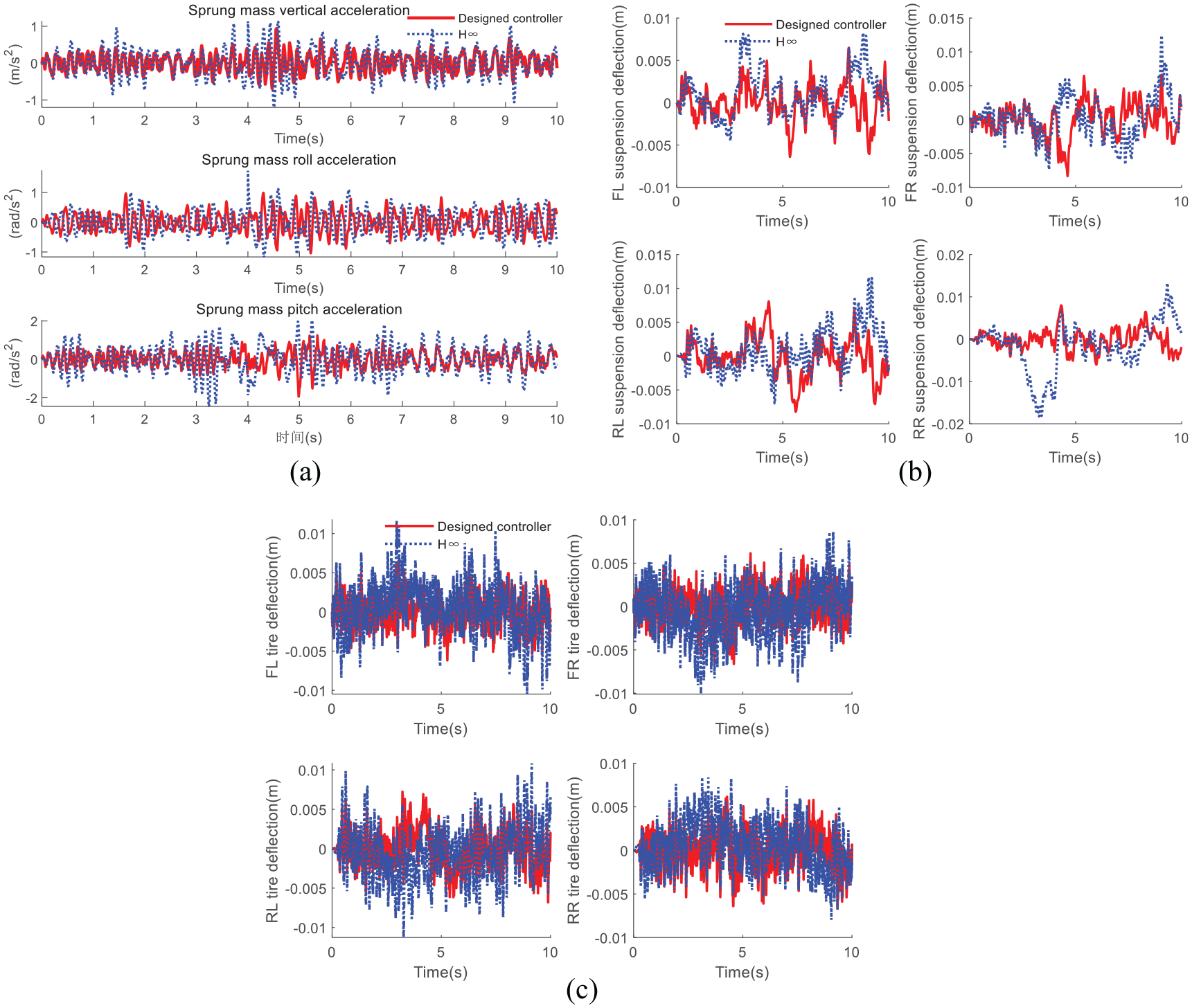
Fault tolerant performance with
It can be seen from Figure 12(a) that the vertical, pitch and roll accelerations with the designed controller can be well controlled in the interval of actuator faults, while the
Conclusions
This study presented a fault observer-based hierarchical integrated control algorithm to process the actuator faults and coupling properties of vehicle chassis model. The observer was designed for the integrated model with respect to unmeasured states and actuator faults, to provide accurate control parameters and improve the reliability of the system. Then, a hierarchical integrated control mechanism was proposed for the integrated model to improve the chassis performance with interferences and failures. Simulation results indicate that the controller can perfectly estimate actuator fault signals and effectively improve the vehicle chassis performance. Conclusions of the study are:
(1) The proposed observer can track the system states and estimate the actuator faults accurately;
(2) The hierarchical control strategy can promote the vehicle performance with different steering input;
(3) The fault tolerant control mechanism can provide excellent characteristics for vehicle chassis system.
The active fault tolerant method was verified under different steering inputs and actuator faults. Future work would possibly concern the following aspects:
Chassis system modeling with consideration of component nonlinearities and longitude dynamic study for further potential exploration of the integrated control system.
Multiple sensor and actuator faults should be considered simultaneously.
More advanced fault tolerant control strategies that could be suitable for the complete failure condition being required for vehicle performance improvement.
Footnotes
Appendix
Declaration of conflicting interests
The author(s) declared no potential conflicts of interest with respect to the research, authorship, and/or publication of this article.
Funding
The author(s) disclosed receipt of the following financial support for the research, authorship, and/or publication of this article: This research was funded by Shaanxi Provincial Key Research and Development Project, grant number 2020ZDLGY16-01.