
Abstract
This manuscript aims for improving the vibrational behaviors of a cantilever beam model through an intermediate lumped mass via offering a new control methodology to suppress for such high oscillations of the system. The equation of the considered cantilever beam structure is gained applying Euler–Lagrange technique. Accordingly, the considered model is modified by mixing Integral Resonant Control (IRC) along with the Nonlinear Saturation Controller (NSC) as anew controller to the considered system. Due to the recommended control technique, the modified system model is studied and analyzed by the perturbation technique. Time histories figures of the measured system plus the new controller are involved to display the response before and after control. The frequency response figures of the modified model before and after new controller near simultaneous condition
Introduction
Robotic manipulators, high-speed apparatus, parts of basic structures and different various models1–5 which are popular common applications of the cantilever beam through a middle of the road lumped mass inside base excitation. Hamdan et al.6,7 diminished huge free vibration sufficiency of a uniform bar per a lumped mass. Al-Qaisia and Hamdan8,9 examined bifurcations and the stability of a nonlinear oscillator excited harmonically. Feng et al. 10 measured the stochastic hop and bifurcations of a cantilever bar within a suffered mass by perturbation process analytically and numerically. Qian et al. 11 studied the asymptotic solutions for the cantilever beam within a lumped mass by homotopy analysis method (HAM). Herisanu and Marinca 12 carried out the free nonlinear vibration of the uniform cantilever beam by rotary inertia and an intermediate lumped mass by optimal homotopy asymptotic method (OHAM). Flexural–extensional huge vibration fullness of non-uniform cantilever pillars loud transversely and pivotally mass is premeditated in Malaek and Moeenfard. 13 Ekici and Boyaci 14 studied the vibration amplitudes of the micro-beams for super-harmonic and sub-harmonic resonances by perturbation technique. They build up that non-perfect limit conditions affect the vibrations of the framework. Mehran et al. 15 premeditated a nonlinear cantilever pillar conveying a halfway lumped mass under harmonic force near different resonances. They originated that the recurrence reaction of the model remains powerfully prejudiced by the damping and force heights. The control of various nonlinear systems has been investigated recently16–20 involved to cantilever beam within intermediate lumped mass. Time delay and various active control methods are public ways in controlling nonlinear structures, numerous researchers are employed on these main various controllers.21–25 Additionally, Liu et al. 26 examined the displacement plus velocity time-delay feedback in a cantilever beam model conveying a lumped mass. Besides, the displacement feedback gain constant makes top sufficiency moving to the short recurrence only, however velocity feedback and their time-delays can be utilized in vibrational stability and reducing the nonlinear vibrations of the model. Alhazza et al.22,27,28 considered the nonlinear vibrations of a cantilever pillar under outer, parametric excitations through directly and nonlinearly time-postpone criticism controllers. They set up that time-postpone criticism controllers are diminished high vibrations framework. The recent paper, introduced a new controller via IRC and NSC together for eliminating the nonlinear vibration and resonance of the considered beam within harmonic excitations. The perturbation procedure is useful to acquire the frequency-response conditions near simultaneous resonance. The numerical solutions and reaction amplitude of this framework are measured and examined. The stability analysis observed via frequency response equations and phase plane procedure at the considered worst resonance case. We determined vibrational graphs and stability study using MAPLE and MATLAB algorithms. The analytical and numerical solutions are in excellent agreement. Comparison between this paper and recent papers of the cantilever beam are prepared.
Measured model
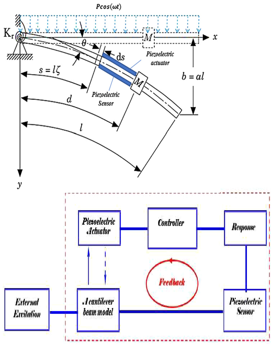
Figure 1 presented a cantilever beam model loud an intermediate lumped mass. The model with a length l and a mass for each unit length m has a lumped mass situated at a distance d from its base. The model is related to a joint rotation spring of stiffness
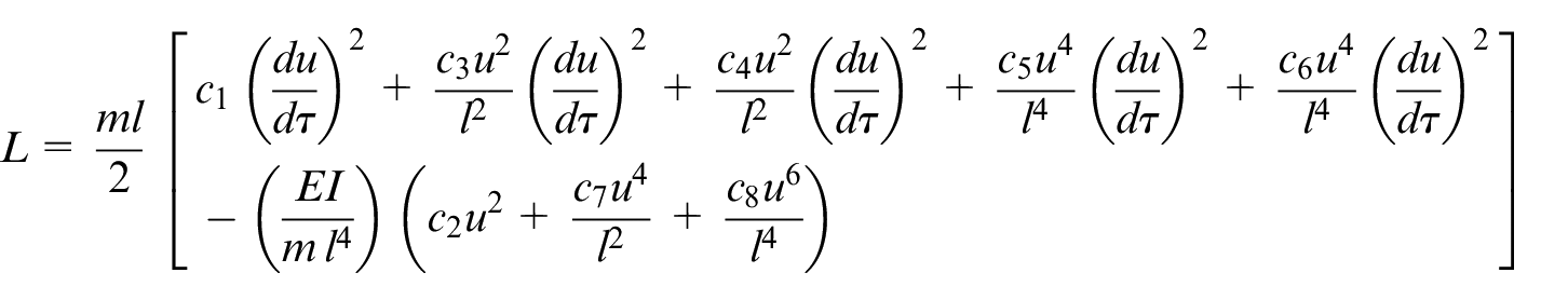
where
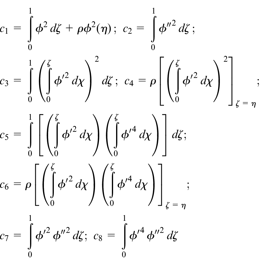
where
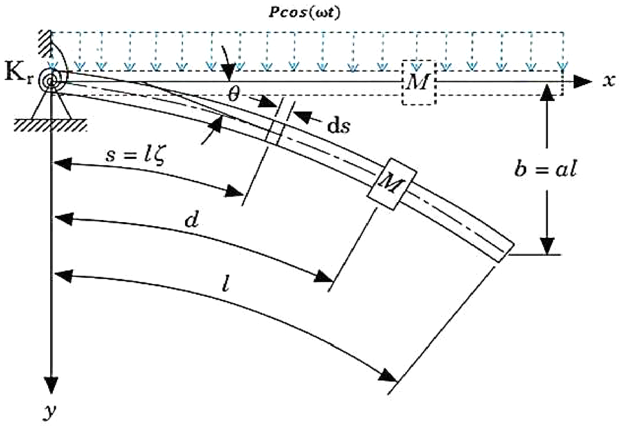
Schematic model of cantilever beam model conveying a lumped mass under external excitation force.
Here, r (
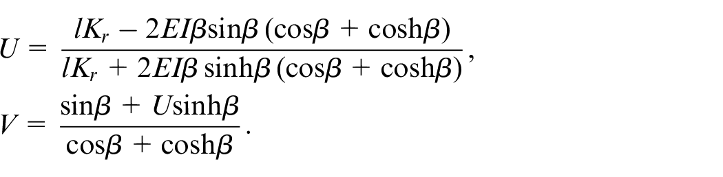
The dimensionless parameters
Where
Mixed (IRC+NSC) controller design
The suggested mixed control is design to reduce the vibration of a cantilever beam model conveying a lumped mass with a collocated piezoelectric actuator and sensor pair as shown in Figure 2.
Controlled system.
By integrating the new controller into system (*) as shown in Figure 3, we have the following equations:
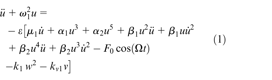


Where
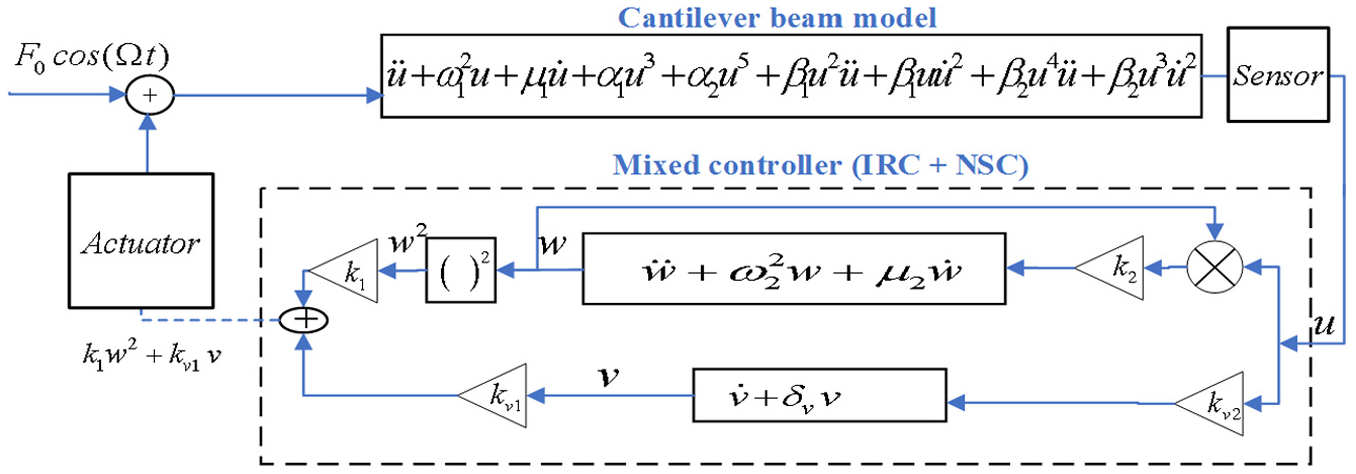
Schematic diagram of cantilever beam model with the controlled system.
Perturbation procedure
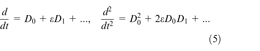
By employing the standard multiple scales perturbation technique (MSTP),29,30 we can get the expansion of


where,
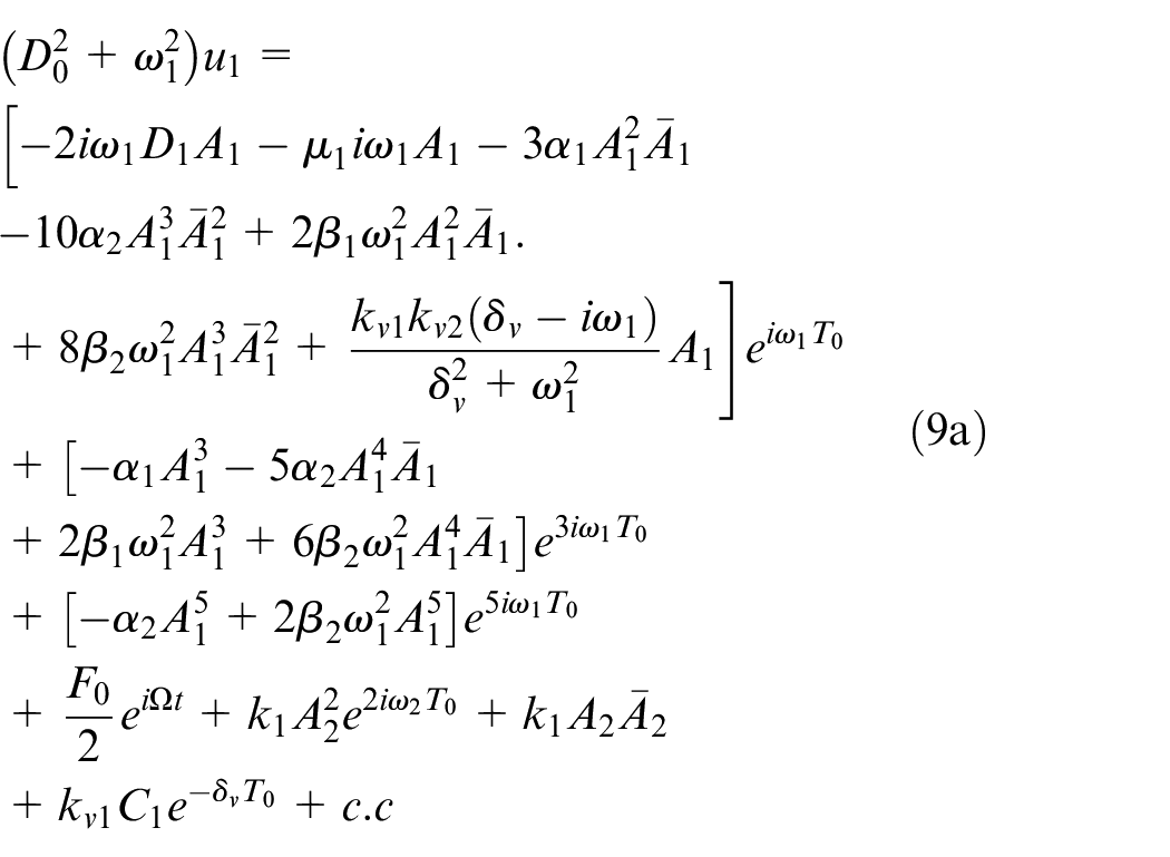
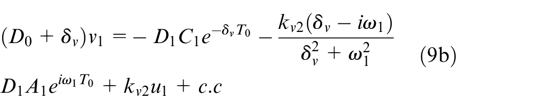
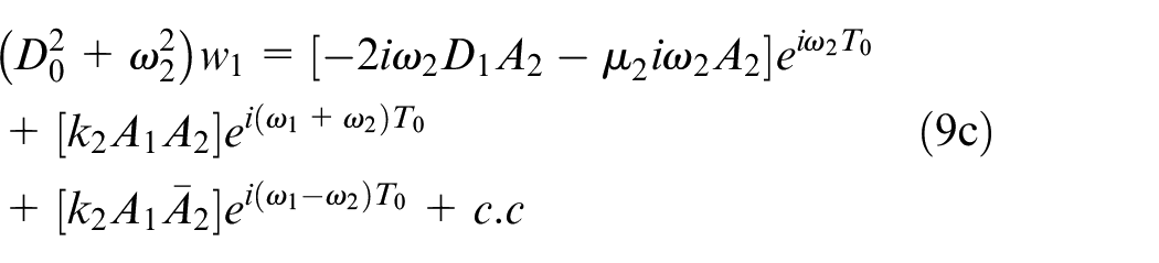
Substituting equations (4)–(5) into (1)–(3), then comparing the parameters of the similar power of


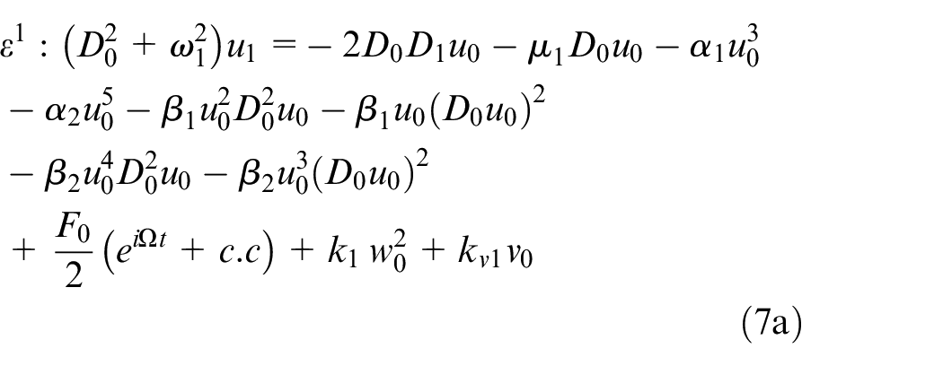

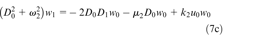
Where, c.c. represents the complex conjugate coefficients. From equation (7) one could get

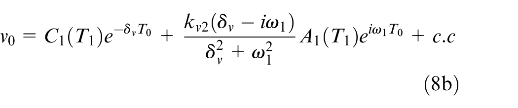

Substituting equation (8) into (7) yields:
Non-dimensional excitation frequency

Taking into consideration equations (10) and (9), one can obtain the secular terms as:
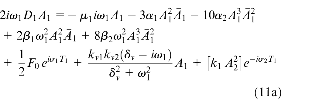

The common term must be wiped out since it brings about an unbounded extension of the reaction of the model, which doesn’t struggle with the physical framework. The complex amplitude
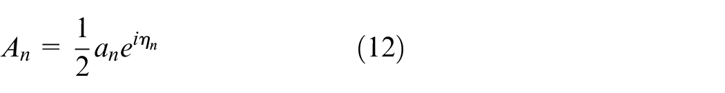
in which
Taking into consideration
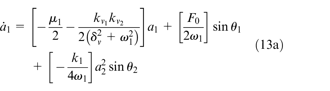
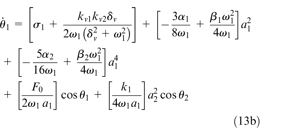
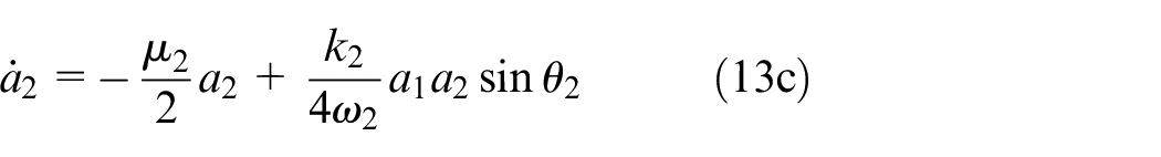
Putting the vibration amplitudes
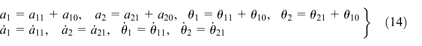
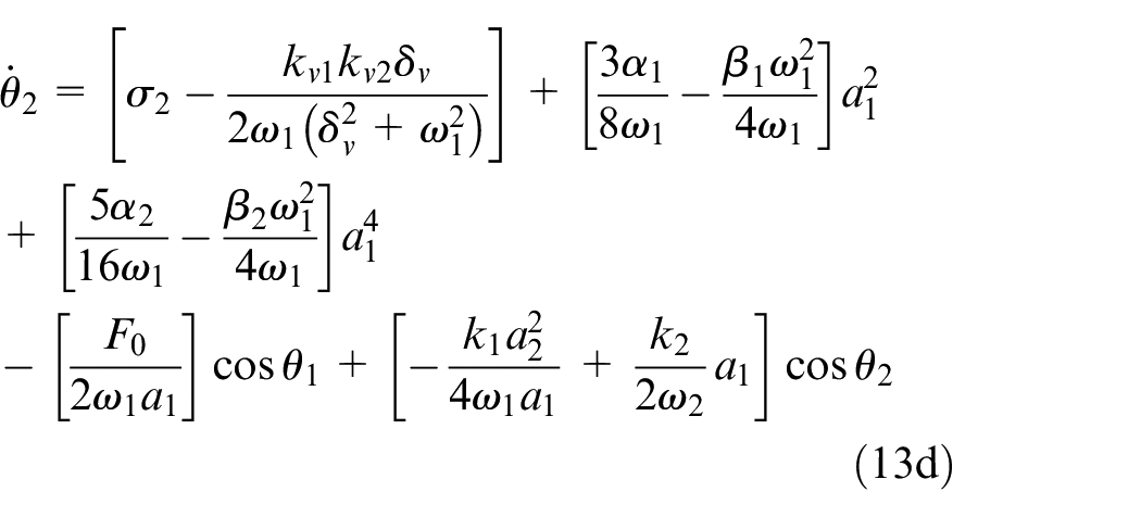
Substituting equation (14) into (13) and expanding for little
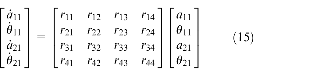
Wherever the over matrix remains the Jacobian matrix of the model and its coefficients entries
Therefore, the solution of the nonlinear framework equation (13) is asymptotically stable if and only if the real piece of every eigenvalue of equation (15) is negative; otherwise, the solution is unstable.
Outcomes and conversation
In this section, we presented all the curves which happened in the considered model before and after addition a new controller.
Figure 4(a) portrays the frequency–response curve of the cantilever beam mode before the control is on at (
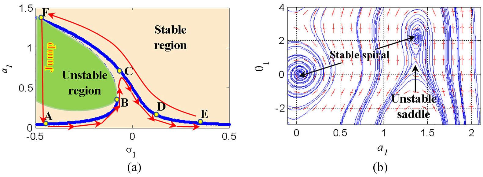
(a) Frequency-response curve
Figure 4(b) portrays the phase sketch of the non-controlled cantilever beam system at
Figure 5 exhibits the difference between the response curves for the system and new control before (blue line) and after (red line) the controller commences in action. It is noticeable that the new controller (IRC + NSC) has a perfect vibration reduction job in the high amplitude’s region (from
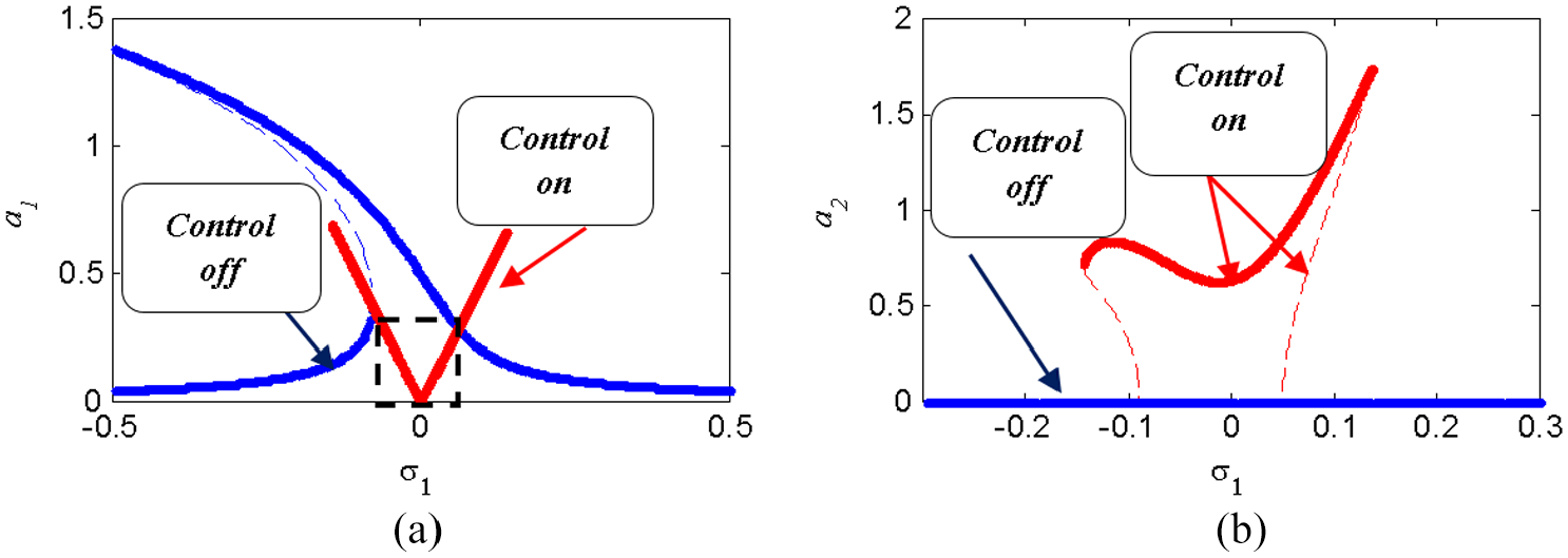
(a) Frequency-response curve of the model, and (b) new controller (IRC+NSC).
Figure 6 portrays the performances of the linear damping coefficient
Effect of varying
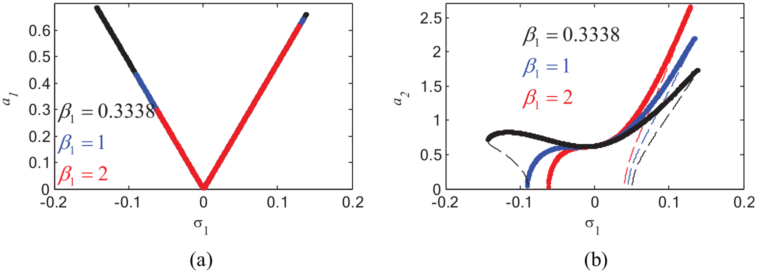
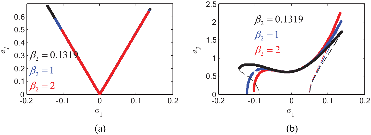
Following, we will discuss the act on varying the nonlinear parameters
Effect of varying
Effect of varying
As a sequel to the curves discussion, at
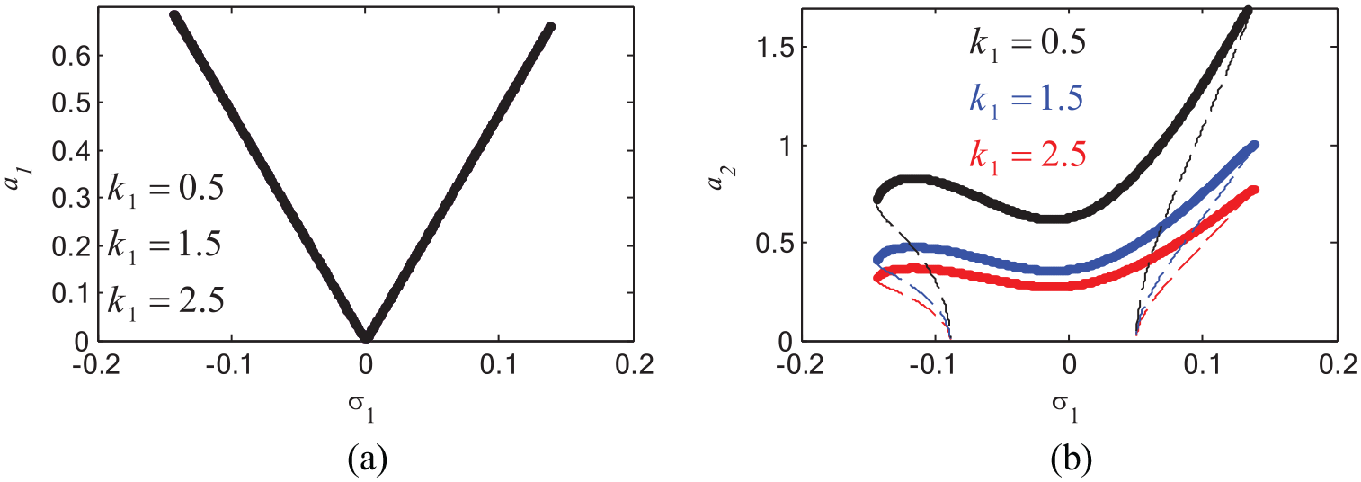
Effect of varying
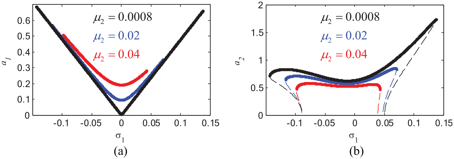
Effect of varying
Figure 11(a) evidences that the amplitude of the system is saturated such the parameter
Effect of varying
From Figures 12 and 13, the response-amplitudes of the model and new controller are monotonic growing when the force amplitude
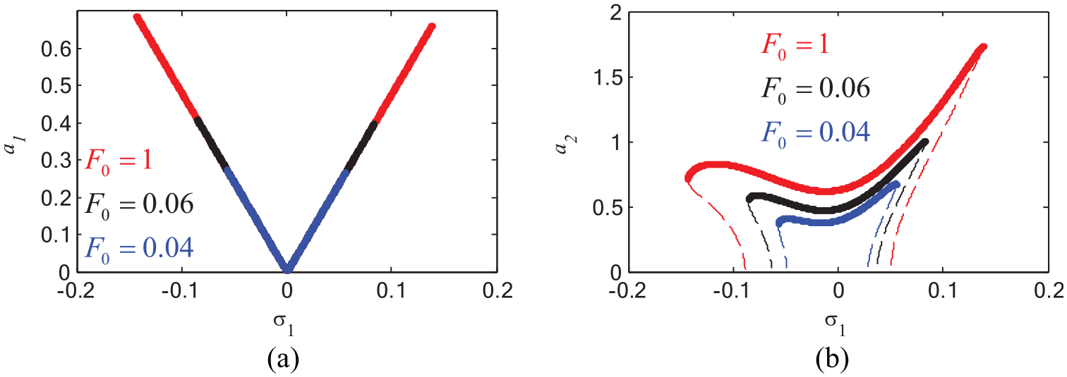
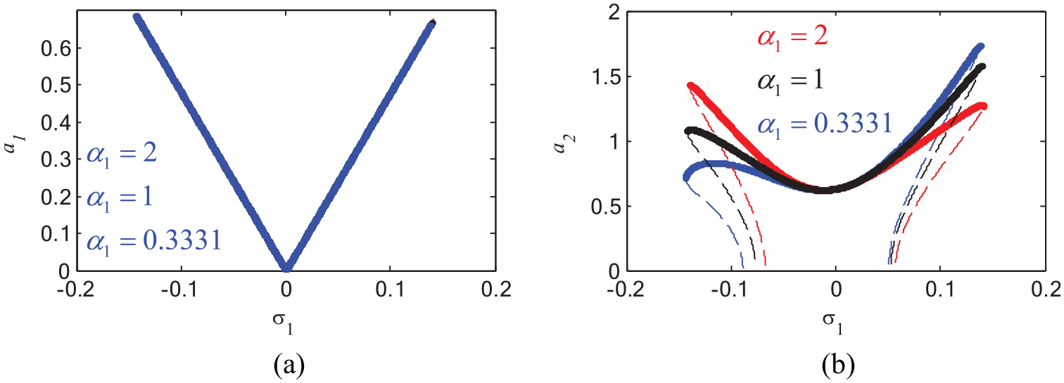
Effect of varying
Effect of varying
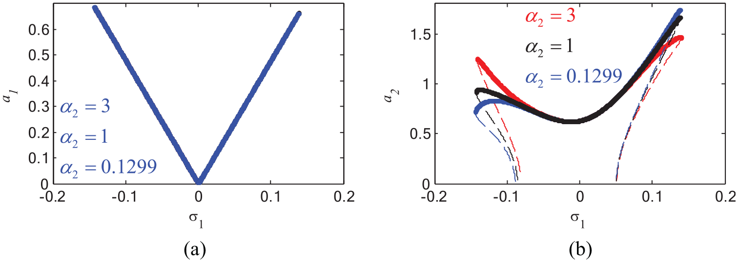
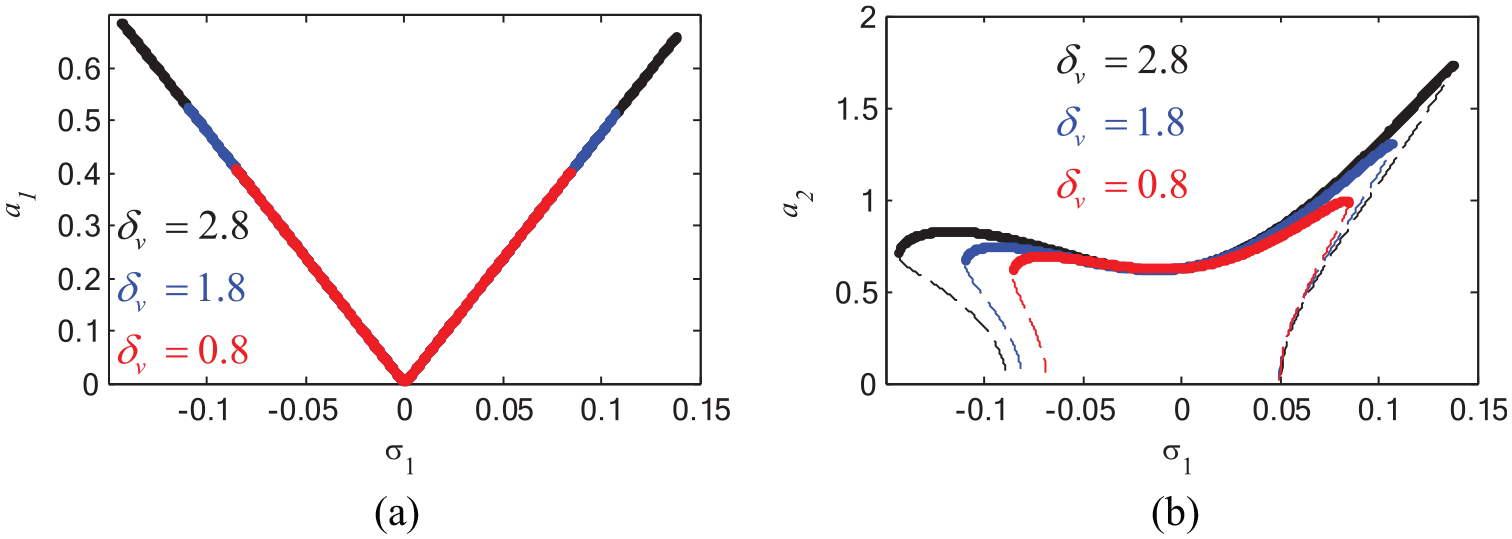
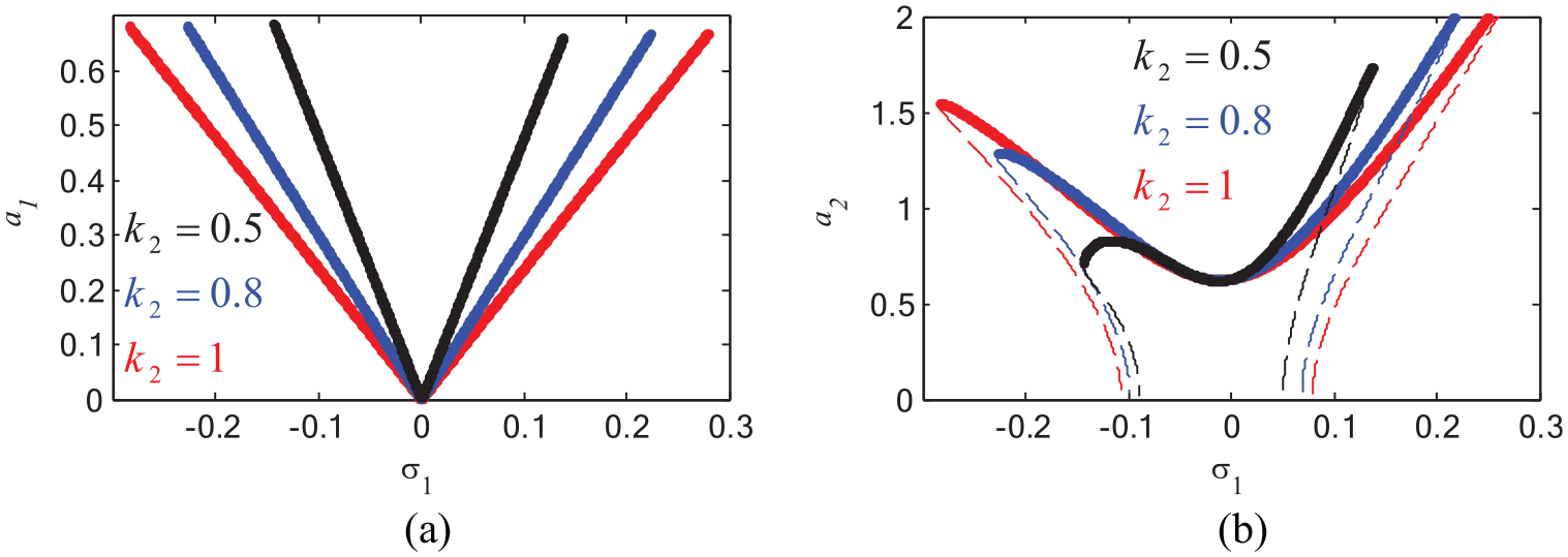
Figures 14 and 15 illustrates that for increasing the values of
Effect of varying
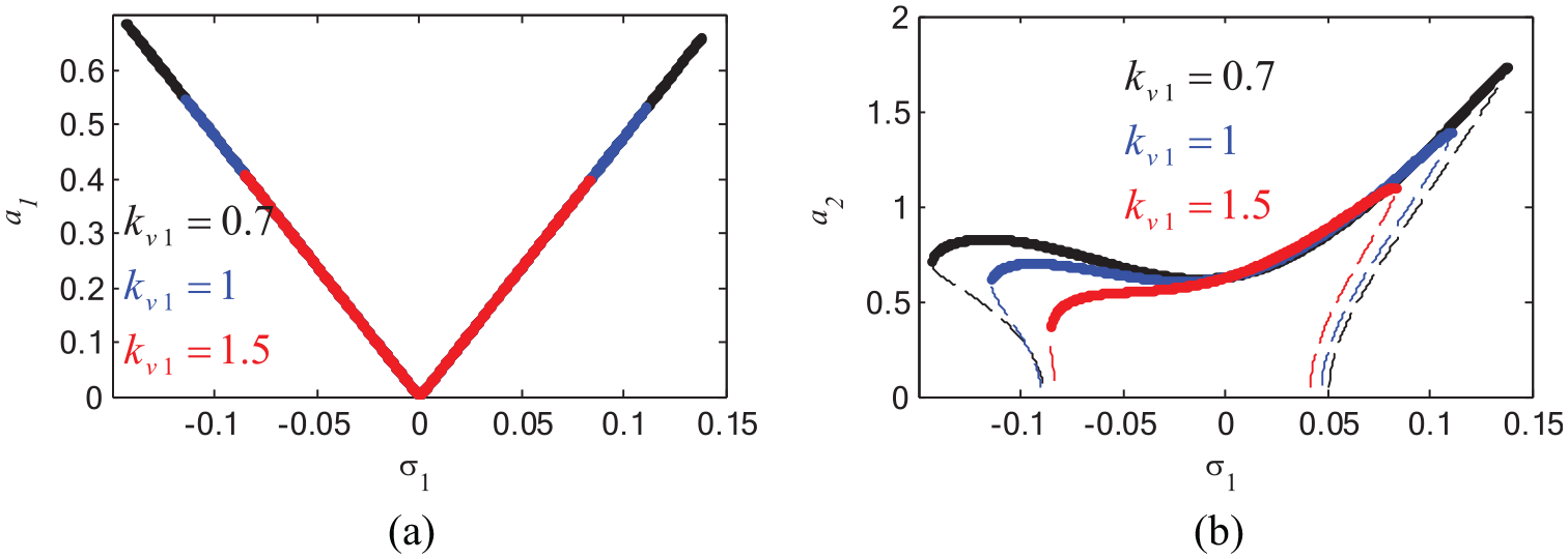
Effect of varying
At
Effect of varying
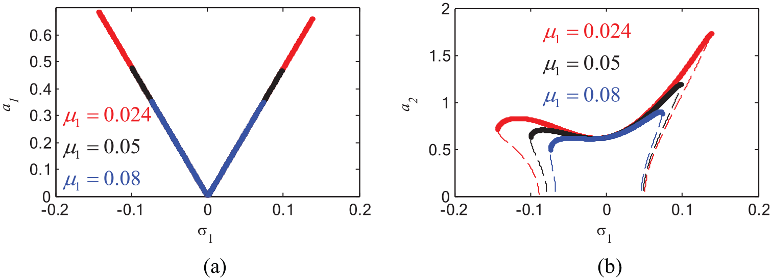
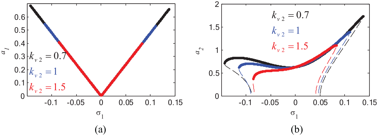
Figure 17, presented the influence of the feedback signal gain
Effect of varying
We have explained the detuning between the excitation frequency
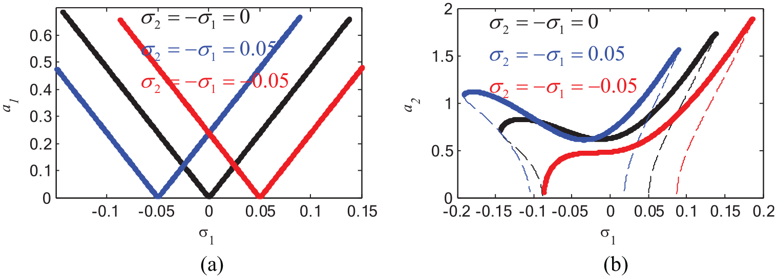
Effect of varying
In this part, equations (1)–(3) which exhibited the measured framework before control plus after joined with different kinds of controls (NSC – new control) are reenacted numerically dependent on MATLAB® software (solver ODE45) to select the chief controller which diminish the vibration with a short time. This study is proposed based on the values of the coefficients presented in the illustrated Table 1:
The parameters values of the measured framework.
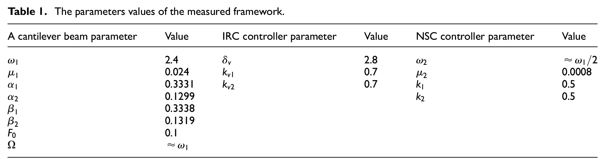
Figure 19(a) portrays the vibration amplitude
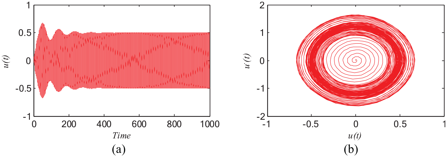
The cantilever beam system without any control.
As well, Figure 20(a) clarified the reduction for the system displacement
The cantilever beam system with different controllers.
Herein, the best possible efficiency in reducing system displacement was developed when creating a new controller by adding the IRC controller
Figure 21(a) shows the system amplitude is about 50% of the external force amplitude
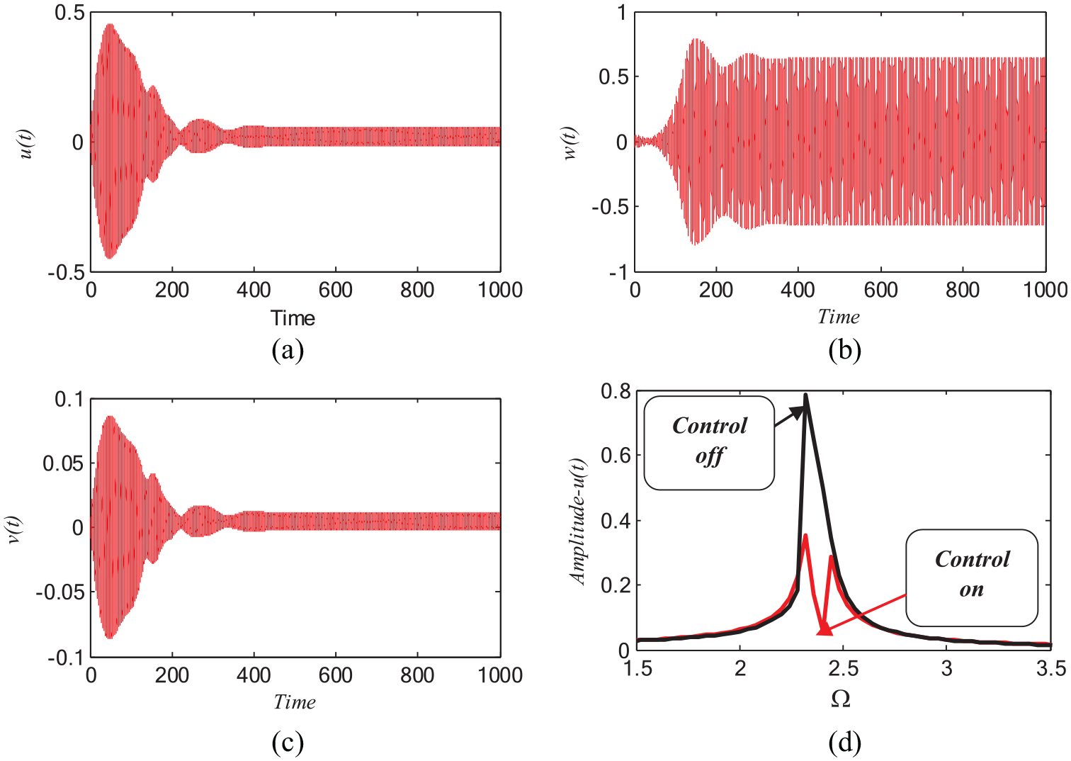
(a) The cantilever beam system with new controller (b–c) the new controller (d) the frequency spectra without and with new controller.
In addition, Figure 22 presented the verification of the result, which obtained from the frequency response equation, as presented in Figure 5 and numerically result of equations (1)–(3) using Runge-Kutta method and plotted on the same figure as the following:
Blue line with yellow circles for the system amplitude before new control and red line with green circles for the system amplitude after new control as shown in Figure 22(a).
Blue line with yellow circles for the control amplitude before the new control is connected and red line with green circles for the control amplitude after new control is connected as shown in Figure 22(b), to display outstanding agreement between the logical and arithmetical solutions.
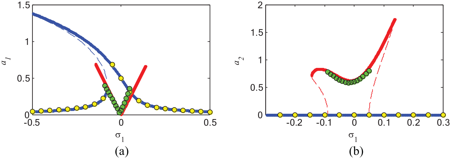
FRC verification before and after new control (IRC + NSC).
Figure 23 declares the comparison between the first order perturbation method given by equation (13) and the numerical solution of equation (1)–(3). Furthermore, the dashed lines appear the modulation
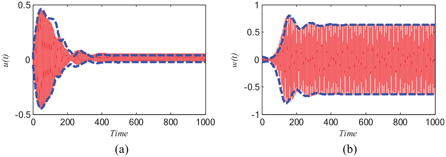
Comparison between perturbation analysis and numerical simulation.
Comparison with different controllers
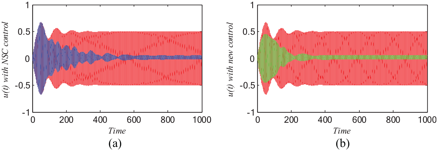
The authors have made a comparison through another controller design’s to verify the “high-performance” of the suggested vibration attenuation strategy and to show the amount of vibration reduction produced by the system using mixed (IRC + NSC) controller at small values of control and feedback signal gains is preferable than that of Integral Resonant Control (IRC), Negative velocity feedback (NVF), Negative displacement feedback (NDF) control and Nonlinear saturation control (NSC) as presented in Figure 24.
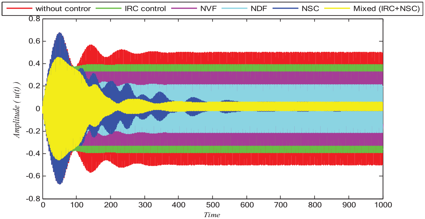
Time history of the a cantilever beam without control and comparison between different controller design’s (IRC control, NVF control, NDF control, NSC control and Mixed (IRC + NSC) control).
Comparison with recent papers
The present effort follows investigates development by the authors in recent articles, see Mehran et al. 15 The authors Mehran et al. 15 studied the cantilever system similar to equation (*), but they studied the behavior of the system under different resonances without any controller effect. Also, the authors Liu et al. 26 controlled the same system with the displacement and velocity time-delay feedback, they established that the controllers reduced the large vibrations of the system under various resonances. The analysis of present a modified work of that the statement made in Mehran et al. and Liu et al.15,26 Moreover, this paper investigates a new controller (IRC + NSC) to the cantilever beam. We act different control methods to the modified system and the new controller on the vibrational structure system. The outcomes of this work appear that eliminate the high vibrational amplitude of the system under harmonic excitation within simultaneous resonance.
Conclusion
In this work a cantilever beam model which loud an intermediate lumped mass under harmonic excitation was studied and derived. Then, we investigate a new control effectiveness of the measured system. The control currents in the cantilever beam system are designed to become a combination of two control signals: One of them is generated via the controller IRC, and the other one comes from the controller NSC. The technique of perturbation is useful to approximate the solution of the measured controlled system. The new controller consists of IRC plus NSC, which is excellent in reduction the vibrations of the cantilever beam system near worst simultaneous resonance case. The numeric stability study was performed to acquire the unstable – stable regions for each frequency response curves. The variety of the amplitude of the model within frequency response curves under new controller was thought and clarified numerically. The outcomes display that the new measured controller is excellent in reduction the vibrations of the cantilever beam system. The influence effects of all coefficients over the modified controlled system within the frequency response curves were fully detailed illustrated in section “Outcomes and conversation.” In this manner, sensible choice of the control framework parameters can viably improve the degree of vibration control for the framework.
Footnotes
Appendix
Acknowledgements
The authors would like to thank the editor and reviewers for their valuable comments and suggestions for improving the quality of this paper.
Declaration of conflicting interests
The author(s) declared no potential conflicts of interest with respect to the research, authorship, and/or publication of this article.
Funding
The author(s) disclosed receipt of the following financial support for the research, authorship, and/or publication of this article: This publication was supported by the Deanship of Scientific Research at Prince Sattam bin Abdulaziz University, Alkharj, Saudi Arabia