
Abstract
This paper investigates the influence of carrier gas flow on the external flow field of coaxial powder feeding nozzle. FLUENT software was adopted to establish gas-solid two-phase flow. The simulation of powder stream field under different carrier gas flow was also carried out. Results show that the larger the flow of carrier gas is, the higher the gas flow field velocity at the nozzle outlet is. At the same time, the concentration at the convergence point is lower, and the convergent point is maintained at 0.015 m. Under the condition of 4 L/min, the powder flow convergence is good. When it exceeds 4 L/min, powder spot diameter increases. The experiment of powder aggregation and laser cladding forming were completed, which shows that the forming effect is the best one under the condition of 4 L/min. It is consistent with the simulation analysis results and has a high reference to the optimization of the process parameters of coaxial nozzle.
Keywords
Introduction
Laser cladding (LC) is a surface repair technique which exhibits many advantages.1,2 For instance, the hardness is high, 3 the substrate has little deformation, 4 the dilution rate is low and the wear resistance shows well. 5 Besides, the LC process is widely used in material processing, surface coating, 6 rapid prototyping 7 and production of more complex parts. 8 Coaxial nozzle is one of the most important parts of the LC system. In the process of delivery, the performance of coaxial powder delivery largely affect the quality and accuracy of the product, which includes the homogeneity and aggregation of powder. The uneven delivery of powder will lead to the uneven appearance of the cladding layer and even block the nozzle pipeline. But the performance of remanufactured products is affected by the poor aggregation of powder, and it is not good for the powder utilization rate, results in reducing the production efficiency and increasing the cost. The carrier gas flow is considered as one of the most important factors which affects the powder transport characteristics. Carrier gas flow affects the concentration, velocity, and the distribution of particle, results in affecting the powder flow aggregation characteristics. The information of the flow field can be completely analyzed by numerical simulation in the model calculation domain. Simulation can also be used to compare many process parameters and influencing factors. Therefore, numerical simulation is a significant way to research the powder flow field during laser cladding. 9
In this respect, some scholars have conducted a large number of relevant experimental studies. Zhang et al. 10 calculated the concentration distribution and aggregation characteristics of the powder particles in the gas-solid flow theory and FLUENT discrete phase model. Dong et al. 11 established a 2D model of gas-powder flow to research the influence of powder feeding and carrier gas flow to the velocity of the powder flow field and the concentration of aggregation point. Yang et al. 12 considered the influence of gravity on powder, a powder flow model of the nozzle was established, and the concept of powder flow focusing and the analytical expression of the concentration field were proposed. Lin et al. 13 established the gas-powder flow in the coaxial feeding nozzle when the Reynolds number was 2000.
Based on the effect of carrier gas flow on the external flow field of the coaxial powder feeding nozzle, a three-dimensional model was established. Except for studying the concentration field and velocity field, the MATLAB software was used to calculate actual distribution of particles on the horizontal surface of the convergence point under different carrier gas flow conditions. The experimental results about four-channel coaxial feeding nozzle were compared with the simulation results.
Numerical simulation of coaxial feeding nozzle
Numerical model of gas-powder flow
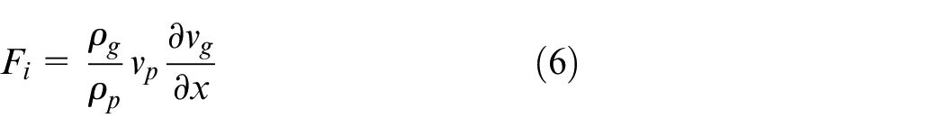
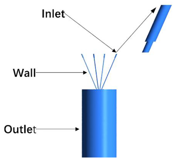
In the process of laser cladding with coaxial powder feeding, the powder flows through the powder feeder tube is sent from the powder feeder to the powder feeder nozzle, and then gathers outside the nozzle under the action of carrier gas, protective gas, and gravity. The powder beam and laser beam intersect at the surface of the substrate together. 14 Flow field analysis of gas-carrying coaxial feeding powder belongs to the category of multi-phase flow numerical analysis. In FLUENT software, gas is a continuous phase.The discrete phase model in Lagrange coordinate system can be selected to simulate particle movement, if the volume ratio of the second phase as the discrete phase is less than 10%. Different computational models have different forms of control equations, which are essentially based on fluid mechanics Navier-Stokes basic equations. The gas phases is solved by the standard turbulence model, and the solution of the discrete phase is obtained by building the particle trajectory model and solving the particle kinematics equation in the discrete phase model studied in the paper. 15 The schematic diagram of powder delivery on coaxial nozzle is shown in Figure 1. For the sake of simplification, the two-phase flow is assumed as follows: (1) the carrier gas and the metal powder have the same velocity, both are uniform flow field; (2) only considering the effect of inertia force and gravity on the movement of powder particles, ignoring the additional mass force, lift, etc.; (3) the influence of the discrete relative continuous phase is ignored, the collision between particles is ignored, and there is no particle pressure and particle viscosity between powder particles, because of the low mass fraction of the discrete phase. 16
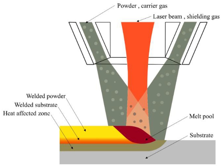
Schematic diagram of powder feeding by coaxial nozzle.
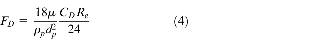
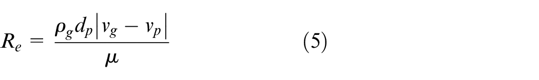
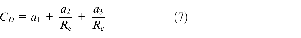
Numerical equation
Continuous phase turbulence control equation
It is considered to be an incompressible fluid because of the low velocity of airflow ejected by the nozzle. Therefore, the N-S equation based on the Reynolds average and the turbulence model is the RNG k-epsilon model for numerical simulation. 17 The heat exchange between the particles and the airflow can be ignored. It is controlled by the continuity equation (mass conservation equation and the momentum conservation equation) in the Euclidean coordinate system. 18
Mass conservation equation:
Momentum conservation equation:
Where
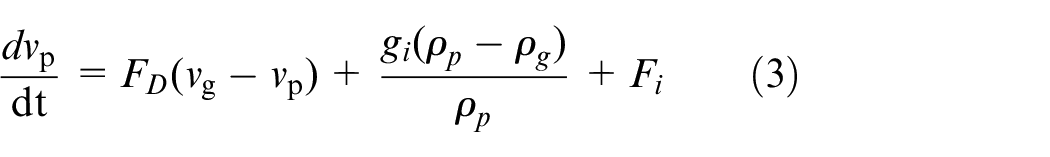
Discrete phase particle orbital equation
The Euler-Lagrange model directly solves the movement trajectory of the discrete particles, which can directly reveal the movement law of each particle. Compared with the Euler-Euler model, it is more reasonable and accurate. The particle satisfies the equilibrium equation under the pull coordinate system:
Where
Where
Establishment of the computational domain and meshing
Combined with the existing nozzles in the laboratory, a four-way powder feeding channel model is established as shown in Figure 2. The nozzle is 66° from the horizontal direction. The inner diameter and length of the incident pipe in the front section are 3.2 mm and 12 mm, and the back section are 2 mm and 100 mm respectively. Vertically the powder carrier airflow is injected at a certain initial speed. The recovery coefficient of powder particles has a certain relationship with the wall surface conditions, incident velocity, material properties, etc. According to relevant studies, the value range of powder particles is generally 0.91–0.99. 19 This paper treats the recovery coefficient as a constant to research, when the powder and wall surface conditions are certain. 20 The mesh generation by Mesh is shown in Figure 3.
Nozzle simulation model.
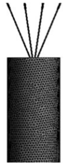
Mesh generation.
Numerical calculation results and analysis
In the process of laser forming, the carrier gas flow varies according to different requirements of the forming process. With a certain amount of powder feeding, there is a simulation about the flow field of powder when the carrier gas flow was respectively 2–10 L/min(Many experimental procedures have proved that when the carrier gas flow rate is less than 2 L/min, the powder flow is easily blocked due to insufficient air force or scattered at the nozzle, and the convergence is poor; when the carrier gas flow rate is too large, the cladding layer is too thick, which is inconsistent with the actual process and the powder utilization rate is extremely low, so only consider 2–10 L/min), and the effect of carrier gas flow on the external flow field of powder feeding by the four-channel nozzle was obtained.
Effect of different carrier gas flow on gas velocity field
As can be seen from the Figures 4 and 5, respectively the nozzle exit powder under the conditions of different carrier gas flow velocity distribution cloud map and the curve diagram, the Figure 4 shows that when the carrier gas flow rate increases, the change of the gas flow field in the pipe and nozzle exit is not obvious at the beginning, then quickly, with the increasing of air velocity, flow field divergence degree is bigger.
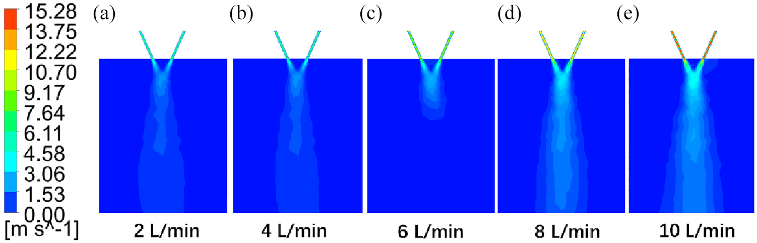
Velocity distribution cloud diagrams at nozzle outlet.
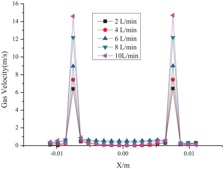
Velocity distribution curve of the nozzle outlet.
Effect of different carrier gas flow to powder flow concentration field
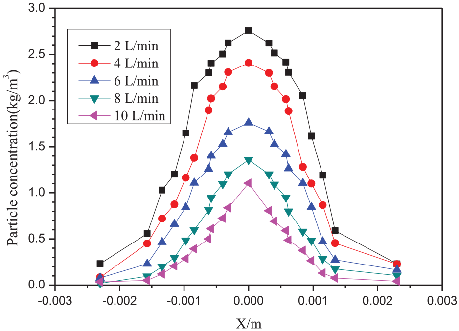
Figure 6 is the vertical section of the calculation domain (the nozzle exit coordinate Z = 0.2 m, the origin of the coordinate is at the lowest end of the air domain). Figure 7 shows that the distribution curve of powder flow concentration in the vertical section under different carrier gas flow conditions. From the Figure 7, when the initial carrier gas flow increases, the powder flow concentration gradually decreased, and the concentration of the aggregation point decreased from 2.7 kg/min to 1.0 kg/min. The focus position is basically unchanged with the focal length at 0.015 m.
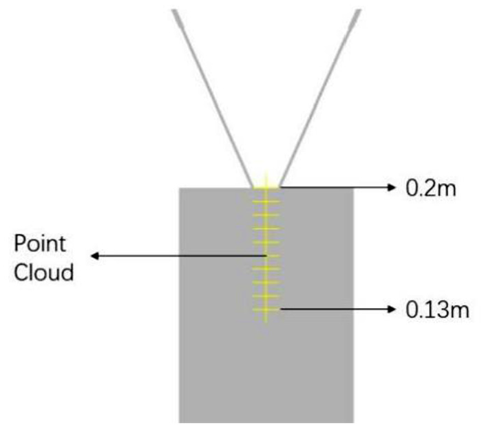
Section Y = 0.
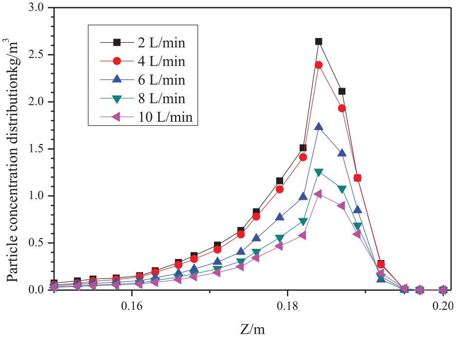
Distribution curve of powder flow concentration in section Y = 0 with different carrier gas flow.
To further research the effect of different carrier gas flows on the focal length position of the powder spot, the points on the Z direction 0.183–0.186 were selected as the abscissa, that is, the concentration corresponding to the ordinate of the focal position when Z = 0.014–0.017 m. It is shown in Figure 8, when the carrier gas flow is 2, 4 and 6 L/min, the focal points are 0.1846, 0.1847 and 0.1848 respectively, that is, the focal lengths are 0.0154 m, 0.0153 m and 0.0152 m, respectively, showing a slight trend of decrease. When the carrier gas flow continues to increase, the focal length does not change, so the carrier gas flow has little effect on the position of the focus.
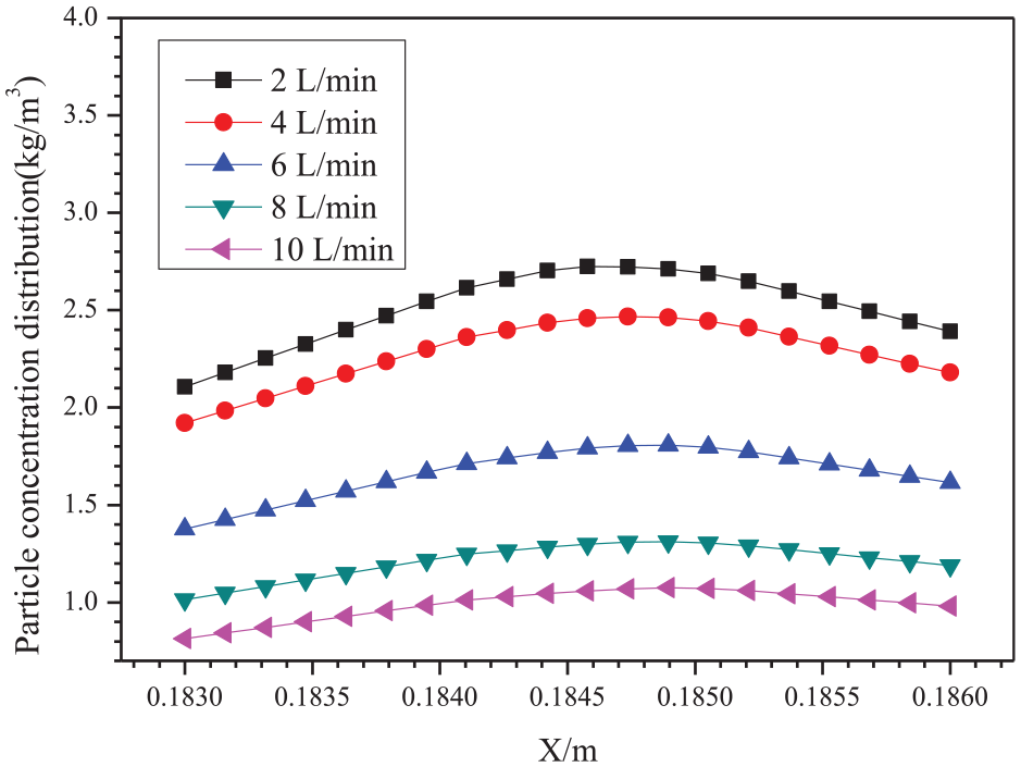
Vertical concentration distribution curve near the focus.
Figures 9 and 10 are respectively the concentration distribution cloud map and curve diagram of the convergence point of the powder flow and outflow field. From the figure we can know that with the increase of carrier gas flow, the concentration of the convergence point decreases gradually. Taking powder spot diameter for focal point on the horizontal direction, powder concentration down to the focal point which the maximum concentration
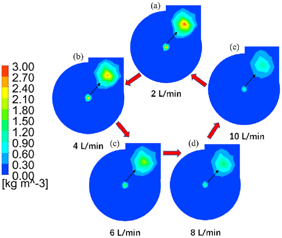
Cloud diagram of powder flow concentration in horizontal profile Z = 0.185 under different carrier gas flow.
Powder flow concentration curve of horizontal profile Z = 0.185 at different carrier gas flows.
The distribution of particles on the horizontal surface of the convergence point
To study the distribution of particles on the horizontal surface of the convergence point, and the focal length is 0.015 m, Figure 11 uses MATLAB software to calculate the number and specific distribution of particle flow on the horizontal surface of the convergence point Z = 0.185 m. The number of particles corresponding to different carrier gas flow is 376, 428, 377, 359 and 334 respectively. Because of the small carrier gas flow, the powder flow is partly deposited in the pipe and the fluidity is poor. Under the large carrier gas flow, the powder flow is affected by the force, and the particles move very fast at the outlet of the nozzle, resulting in serious powder flow diffusion in the external field. As can be seen from the figure, it is only 4 L/min, the particle distribution is relatively concentrated and the powder flow has the best aggregation.
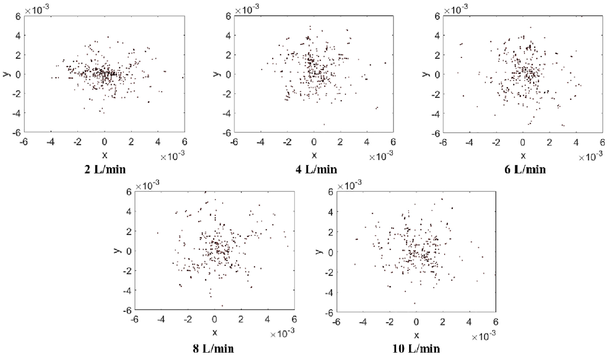
Particle distribution on the horizontal plane Z = 0.185.
Experimental research
To verify when other conditions are certain, the optimal set value of carrier gas flow is 4 L/min. This paper conducted experimental research on the aggregation of powder flow in combination with relevant equipment in the laboratory. With the rapid development of smart manufacturing, data generated by machines and devices is boosting and can be collected well. 22 The main equipment used in the experiment includes Figure 12: Powder feeder (RC-PGF-D-2); Laser (LDF6000-60); Nozzle (RC-LDM-8060); High-speed camera (PCO. Dimax HD); 45 steel, etc. The gaseous material is nitrogen (better nitrogen stability,density 1.138 kg/m3). Future energy consumption will increase as societies continue to develop. 23 Since the development of laser cladding technology, the first choice of cladding materials is iron-based, cobalt-based and nickel-based self-melting alloy powder. 24 So the solid powder is iron base alloy powder (100–320 meshes).
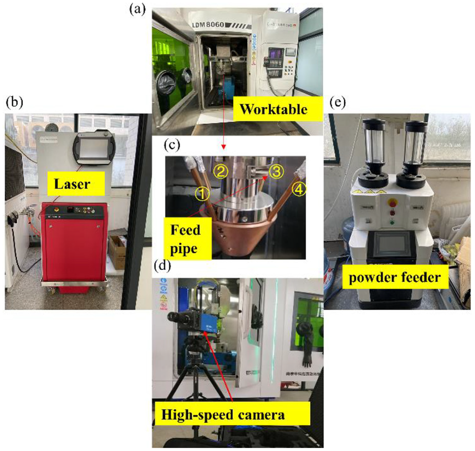
Experimental equipment.
Experimental analysis on powder feeding stability
To research the effect of carrier gas flow on the stability of powder delivery, keep rotating speed of the powder plate unchanged (1 r/min), and measure the corresponding powder delivery amount when setting the carrier gas flow as 1, 2, 3, 4, 5, 6, 7, 8, 9 and 10 L/min respectively. We can see from the figure 13, with the increase of carrier gas flow, the powder output gradually increases at the beginning. When it exceeds 4 L/min, the powder output has a small change trend and finally tends to a stable state, indicating that the powder output of the feeder does not increase limitlessly with the increase of carrier gas flow.
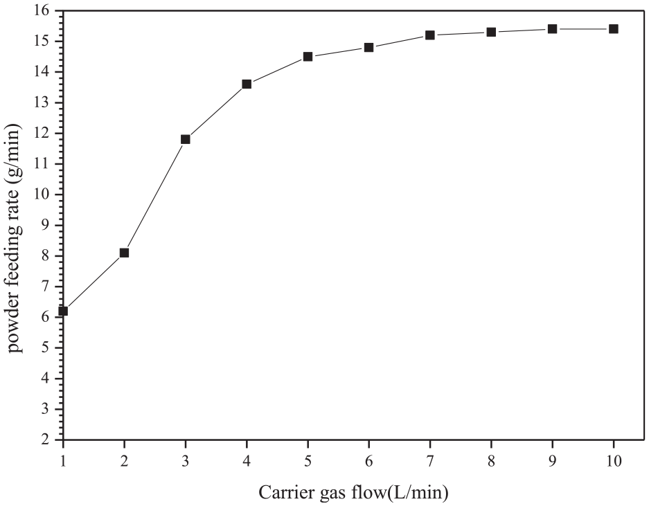
Relation curve of carrier gas flow and powder feeding rate.
Powder aggregation experiment
This experiment studied the cladding effect under different carrier gas flow, with the laser power was set at 1800 W, the powder feeding rate was 13.6 g/min, the scanning speed was 900 mm/min, and the spot diameter was 3 mm. The cladding results were shown in Figure 14. According to the figure, as the carrier gas flow is too low, the cladding morphology is uneven. As it is too high, the powder is more sticking. When it is 4 L/min, the cladding effect is better.
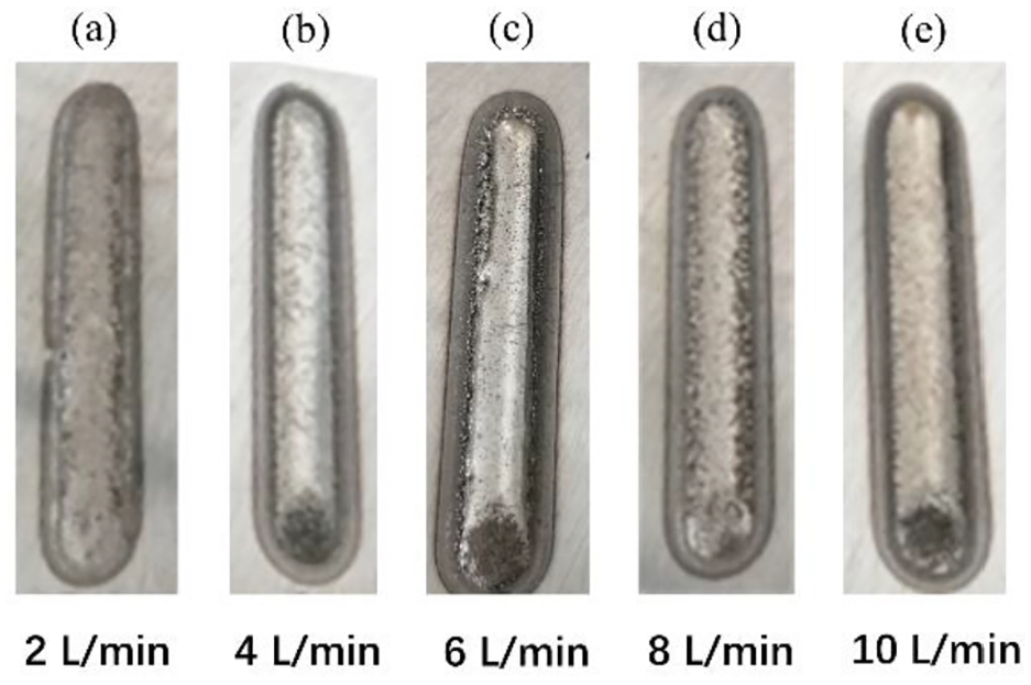
Cladding morphologies under different carrier gas flows.
For observing the powder aggregation of the outflow field of the nozzle, experimental results taken by PCO. Dimax HD were compared with the simulation results. From Figure 15 we can see that the powder flow has a well convergence. According to the shooting results, the distance between the powder flow convergence point and the nozzle is 15 mm, which is consistent with the simulation results.
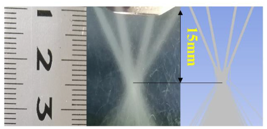
Comparison between the shooting results and the calculated results.
Conclusion
Based on several experiments discussed in this paper, the following conclusions can be made: The powder flow concentration is affected by the carrier gas flow and shows an inverse proportional relationship. The concentration at the aggregation point decreases obviously, when the carrier gas flow increases. The carrier gas flow has little effect on the focal length of the powder flow convergence point, which is 0.015 m away from the nozzle outlet.
The carrier gas flow affects not only the concentration of the powder flow but also the motion state particles. The velocity of the airflow near the nozzle outlet obviously increases as the increase of carrier gas flow.
If the carrier gas flow is under 4 L/min, the powder spot diameter is slightly smaller than laser spot diameter. When it exceeds 4 L/min, the powder spot diameter increases 0.1–0.8 mm larger than the laser spot diameter. As the diameter of the powder spot is slightly smaller than the length of the laser spot, the cladding effect is better. Therefore, when carrier gas flow exceeds 4 L/min, powder adhesion will be more serious, which is not conducive to improve the utilization rate of the powder.
Footnotes
Appendix
Declaration of conflicting interests
The author(s) declared no potential conflicts of interest with respect to the research, authorship, and/or publication of this article.
Funding
The author(s) disclosed receipt of the following financial support for the research, authorship, and/or publication of this article: This study was supported by Key scientific research project of higher education institutions in Henan Province (20A460033)(19A460035); National Natural Science Foundation of China(51701244)(51705545); Science and Technology Guidance Project of China Textile Industry Federation (2016085) Subsidized Project of Open Laboratory for Key Disciplines of Modern Manufacturing Equipment and Instruments in Henan Universities (2017MEI002)