
Abstract
In the hardware-in-the-loop simulation, the goal of electric loading is to realize the accurate tracking of the torque signal and test the performance of the aircraft actuator system. For some high dynamic aircraft, it is necessary to reduce the influence of the surplus torque to increase the system frequency band. This paper introduces a new electric loading system which adopts a double-loop servo motor as the torque loading mechanism. It applies two loops to track the position of the rudder and the aerodynamic load spectrum respectively. For the purpose of reducing the disturbance between two loops of the scheme, a two-DOF H∞ robust controller is designed, which improves the robustness of the system effectively. The simulation results show that the new system increases the upper limit of 25 Hz frequency band of the traditional single-loop system with PID control to the maximum of 40 Hz. The double-loop system thereby meets the technical requirements of the hardware-in-the-loop simulation experiment for high dynamic aircrafts.
Introduction
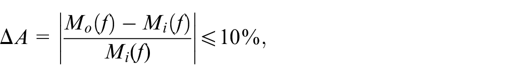
Loading system is one of the main equipment for hardware-in-the-loop simulation. It is used to simulate the aerodynamic load on the aircraft control surface under laboratory conditions and test the performance of the aircraft rudder system. 1 The aerodynamic torques acting on the aircraft control surface during flight can be further decomposed into corresponding load spectra. 2 From the engineering point of view, the frequency band of the actual loading system must be higher than that of the load spectrum in order that the system can accurately reproduce the aerodynamic load on the control surface. 3 In engineering, the frequency band of the loading system is usually defined by the maximum operating frequency band that meets the “dual-ten” index, that is, the amplitude error between the torque instruction and the output torque is less than 10%, and the phase difference is less than 10°. Since the beginning of this century, the technology of electric loading system with the frequency band of 20 Hz has been relatively mature. 4 However, with the development of modern air warfare, higher speed requirements are put forward for air-to-air missiles. The torque frequency acting on some small rudders has reached more than 30 Hz. 5 The current loading schemes cannot fully meet the test requirements of high performance systems.
In practice, the displacement output generated by the rudder system and the torque output generated by the loading system will be coupled with each other. 6 This coupling action causes redundant and unexpected mechanical disturbance in the servo motion, which is called “surplus force” in academic circles. Surplus force causes a serious impact on the accuracy, frequency response and stability of the loading system.7,8 It is necessary to introduce an effective control method to suppress it.
In general, the restraint of surplus force can be carried out from two aspects, including the selection of system structure and the improvement of system control methods. 9 For system selection, the literature 10 introduces the development and current situation of the electric loading system, and points out that at present its actuators mostly adopt single-loop permanent magnet motors. Literature 11 introduces an elastic element called spring rod into the system, which reduces the surplus force of the system and improves the loading performance from the structural point of view. In reference, 12 permanent magnet synchronous motor is used as a matched loading motor, and the influence of the mechanical inertia and driving mode of the motor on the system frequency band is discussed. Literature 13 proposes a low speed and high torque loading scheme using double-stator motor to reduce the influence of surplus force on the loading motor. Nevertheless, the surplus force cannot be completely suppressed due to the synchronous stator’s own electrical inertia. The suppression rate for surplus force is about 90% at 10 Hz.
In terms of control strategy, literature14,15 respectively introduce AC electric loading systems with advanced PID control and fuzzy self-adaptive control, and the operating frequency band reaches 20 Hz when the “dual-ten” index is met. The H∞ controller designed in literature 16 suppresses the surplus force of the rudder. However, due to the special algorithm and uncertainty of the allowable range, it is complicated to calculate the ideal single-DOF optimal H∞ parameters in engineering.
Traditional single-loop loading systems are designed on the basis of torque index, without paying attention to the position index. They are affected by the surplus torque generated by the position disturbance, which results in a great limitation of system frequency band. In view of the limitation of the single-loop structure, a double-loop loading system is introduced in this paper. The scheme attempts to track the position output of the rudder by using an independent position loop to reduce the influence of the position disturbance on the torque loop. With the double-loop structure, passive loading tracking is approximately converted into active loading. It is where the innovation of this paper lies. In addition, a H∞ controller is designed to reduce the coupling force between two loops and improve the robustness of the system. If the system designed in this paper is successfully applied, it will effectively suppress the surplus force, thus improving the frequency band of the loading system, which is of great significance to the high frequency band actuator loading in hardware-in-the-loop simulation.
Mathematical model of electric loading system
System mathematical model
A typical structural diagram of the electric loading system is as shown in Figure 1, in which, the servo motor is the actuator of the loading system and applies the load according to the torque instruction. The spring rod is used to adjust the specific connection stiffness coefficient between the bearing object and the loading system to dominate the surplus force. 17 The torque sensor is used to measure the torque applied by the loading system on the rudder and form a closed torque loop. The rotary encoder is used to measure output signals such as the position and speed of the rudder. The rotary inertia simulation mainly simulates the rotary inertia of the control surface so that the load on the rudder is close to the flight state.
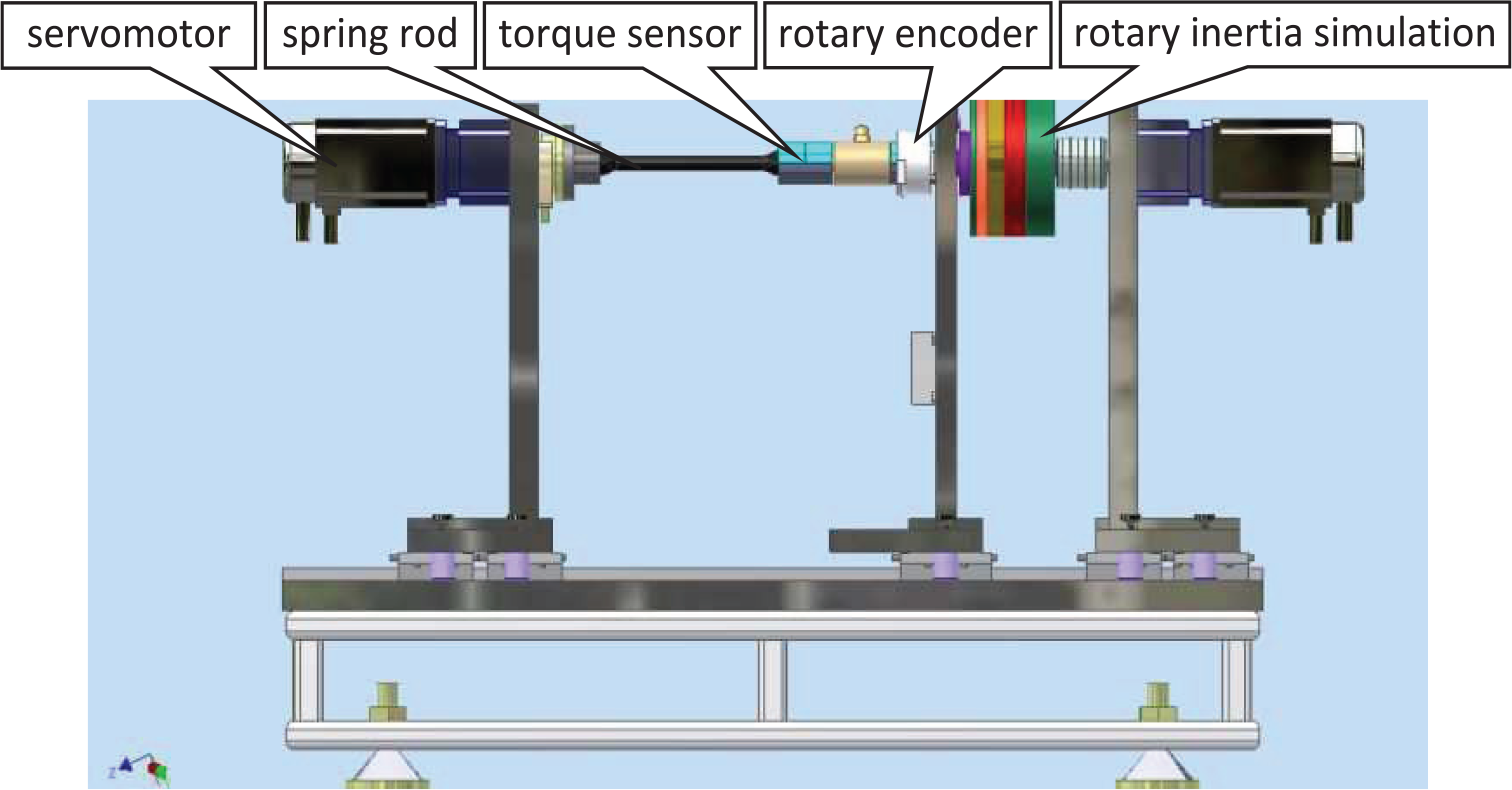
Typical structural diagram of electric loading system.
The loading system adopts a closed torque loop control mode. The control computer receives the instruction torque signal and outputs it to the servo motor drive controller. Meanwhile, it receives the feedback signal from the torque sensor and the rotary encoder to form a closed torque loop so that the system can apply the loading torque to the rudder according to the instruction in order to realize the torque servo control. 18
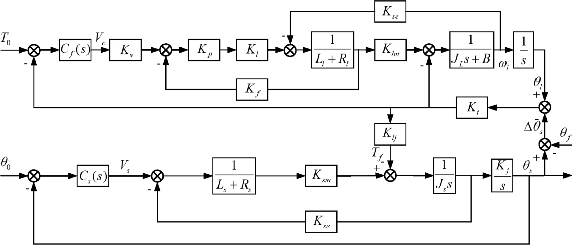
By analyzing the operating principle of the loading servo motor and the generation mechanism of torque, a mathematical model of the loading system is obtained, as shown in Figure 2. 19
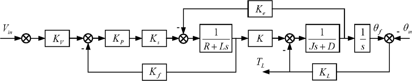
Mathematical model of servo loading system.
Where
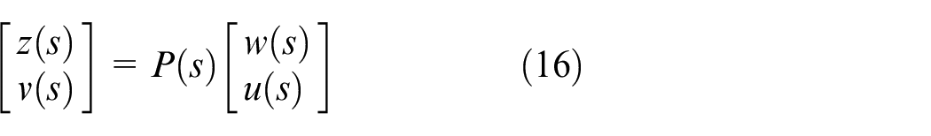
Analysis on surplus force
By analyzing the mathematical model of the loading system, the actual torque output

Where G(s) is the equivalent transfer function of the loading system.
The minus in
Structure and mathematical model of double-loop loading system
Structure of double-loop loading system
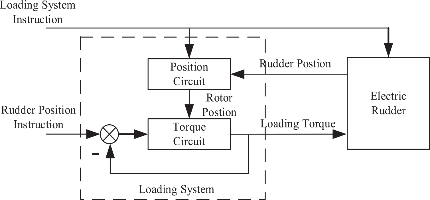
The main factor affecting the performance of the loading system is the surplus force, which is generated by the motion of the bearing object. The motor of the loading system needs not only to apply load according to the torque instruction, but also to quickly track the motion of the rudder. 21 If the loading motor is divided into two parts, one part is used to carry out loading and the other part is used to follow the motion of the rudder, the surplus force caused by the position disturbance can be minimized. Under the ideal condition that the position output of the system completely follows the loaded rudder, the surplus force will be completely eliminated. 22
Therefore, the paper puts forward the idea of double-loop loading system. Its schematic structural diagram is as shown in Figure 3.
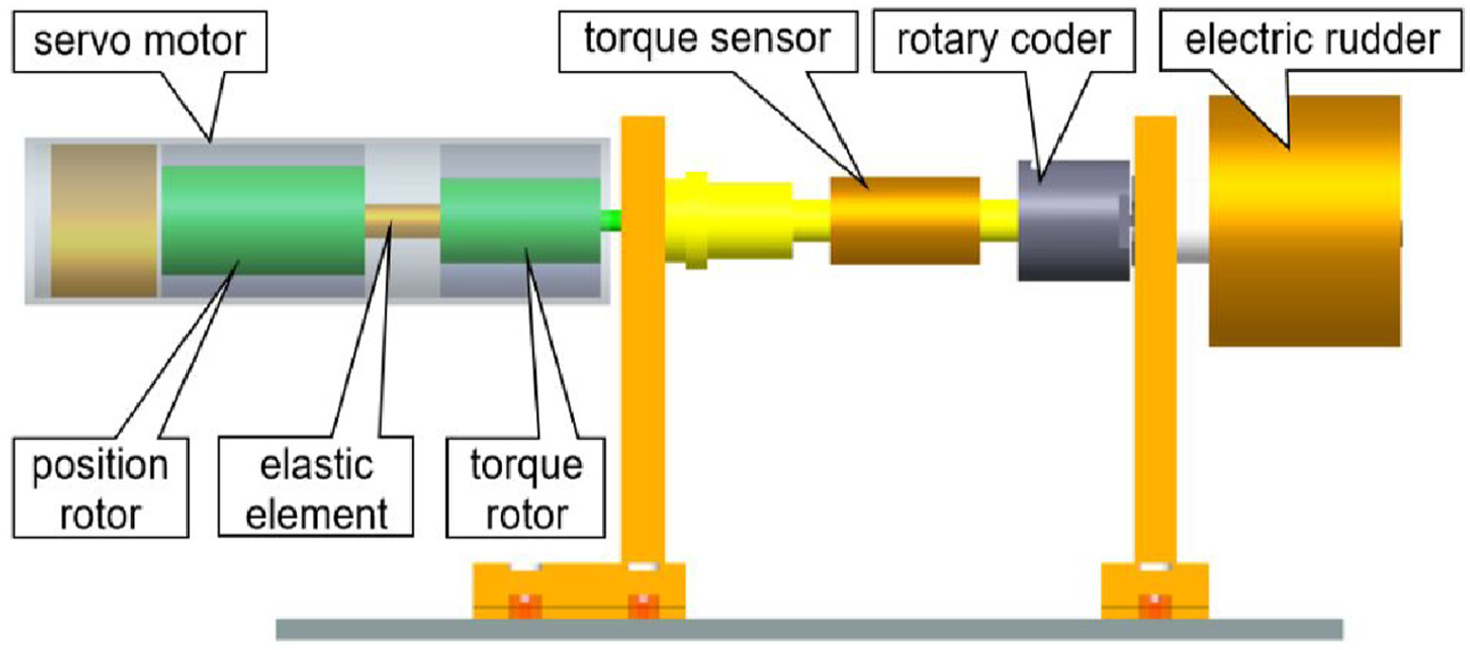
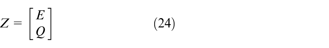
Schematic structural diagram of double-loop electric loading system.
The structural difference between the double-loop loading system and the single-loop loading system is that the motor uses double rotors, which are respectively called position rotor and torque rotor in this paper. The position rotor receives the position instruction of the loaded rudder to form a closed position loop synchronized with the motion of the rudder. The torque rotor is connected with the position rotor through an elastic connection element and moves along with the position rotor. In which, the function of the elastic element is to connect the torque rotor with the position rotor, so that the position rotor can drive the torque rotor to rotate. At the same time, buffer is added between the position rotor and the torque rotor to reduce the influence of the tracking error of the position loop on the torque loop.
The basic idea of eliminating surplus force is that if the position rotor in Figure3 can move synchronously with the loaded rudder, the motion of the loaded rudder will not cause additional disturbance to the torque loop in theory. That is to say, when the expected loading torque of the torque rotor angular position motion of the loading motor is zero, and it is synchronous with the rudder angular position motion, there will be no extra force caused by the rudder motion.
The instructions of the double-loop loading system include two items, one of which is the loading instruction of the loading system, that is, the instruction torque of the torque loop, and the other is the position instruction of the rudder, that is, the input instruction of the position loop. The output also includes two items, one is the loading torque of the loading system, and the other is the rotor position of the position loop. Therefore, the double-loop loading system is a typical double-input and double-output system. Its position loop and torque loop are independent and interact with each other. Its functional block diagram is as shown in Figure 4.
Synchronization control schematic diagram of double-loop electric loading system.
Establishment of mathematical model
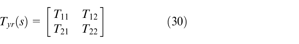
Mathematical model of position loop
Based on the analysis on the mechanism of the double-loop loading system, the main function of the position loop motor in the system is to drive the torque loop motor to move synchronously with the rudder, making it a typical position servo system. Its rotary inertia is equal to the sum of the rotor rotary inertia of a position loop motor and the rotary inertia of a torque loop motor. Therefore, the open loop transfer function of the position loop can be obtained as follows.
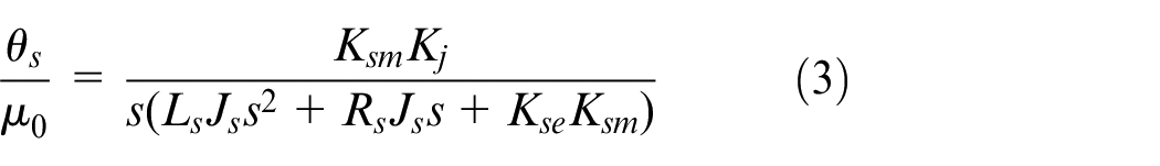
Where
The transfer function from the disturbance torque
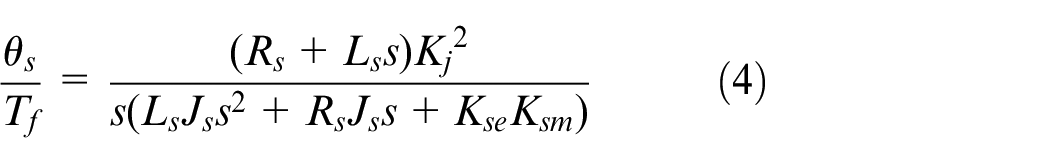
Mathematical model of torque loop
The torque loading loop is realized by a torque rotor installed on the position rotor. A DC brushless motor is adopted as the loading motor here due to its fast dynamic response, high flux density and power factor. 23 Unlike traditional loading systems, the loading motor of the torque loop in the double-loop loading system moves synchronously with the rudder along with the motion of the position loop. At the same time, its output shaft is connected with the rudder through a torque sensor to apply the desired load torque. Therefore, the torque between the loading motor and the rudder is

Where
Under the traditional loading mode, this angle difference refers to the angle difference between the servo angle and the loading motor angle. While in the system studied in this paper, the value of this angle difference is equal to that of angle difference between the loading motor angle

Thus, the mathematical model of torque loop can be derived as follows. 24
System characteristic analysis
In combination with the control block diagrams of the position loop and torque loop, the overall working mechanism model of the double-loop synchronous loading system is obtained as shown in Figure 5.
General block diagram of double-loop synchronous loading system.
From the general block diagram, it can be seen that the double-loop synchronous loading system is a kind of multivariable control system. The input signal of this system includes the actual position signal
There are two coupling relationships between the two loops. (1) the position difference between the angle output by the position loop and the rotation angle of the rudder is coupled to the torque loop, and (2) the loading torque of the torque loop is coupled to the position loop through the speed reduction ratio. The above two coupling relationships make the position loop and torque loop interfere with each other, generating the surplus force which restrict the system performance. Therefore, they should be improved.
The simplified block diagram of double-loop synchronous loading system is as shown in Figure 6.
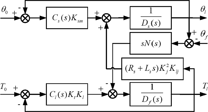
Simplified block diagram of double-loop synchronous loading system.
Let
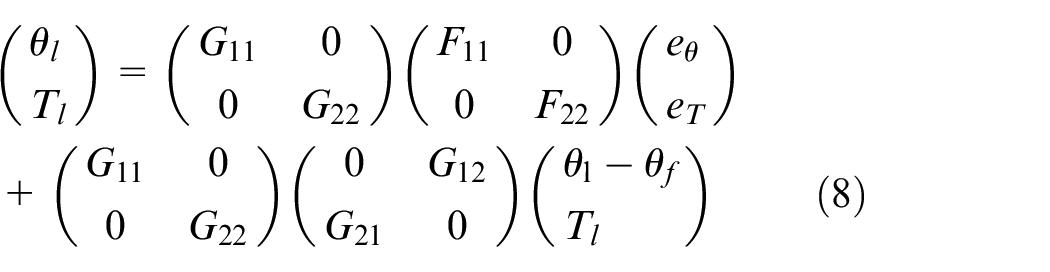
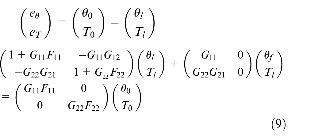
It can be seen from equation (8) that, if the output angle
Where
Make the characteristics of the position loop as close as possible to the characteristics of the rudder, that is
For this type of double-input/output system, the other core design index is to reduce the coupling between the position loop and the torque loop, so as to improve the loading precision and dynamic range of the torque loop motor.
System controller design
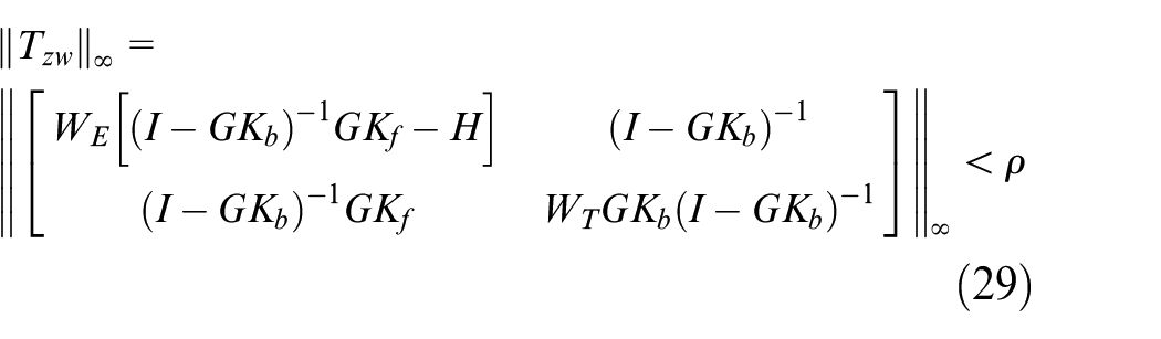
In the mechanism model obtained from the above section, for this kind of double-input/output synchronous system, the core design index includes reducing the coupling of the position loop to the torque loop and improving the precision and dynamic range of the torque loop. 26 In this section, H∞ optimization method is employed to design the control system of the double-loop synchronous loading system, and the anti-interference capacity and tracking capability of the system are improved through weighting function.
Definition of two-DOF H∞ controller
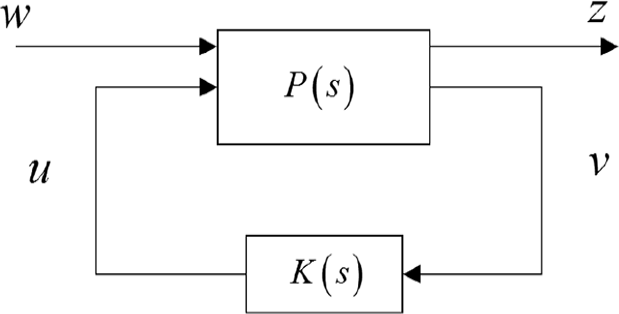
When designing the control system, the motor of the position loop is required to quickly and accurately track the angular position output of the rudder, so the control system is designed by adopting a two-DOF controller. The design of traditional single-DOF controller has contradictions in signal tracking and disturbance attenuation of the system. Two indexes cannot be optimized at the same time. The two-DOF controller can control the tracking ability and anti-interference ability respectively rather than single-DOF controller, so that the system performances are significantly improved. 27
The structure chart of two-DOF H∞ controller is as shown in Figure 7. 28
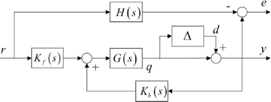
Structure of two-DOF H∞ control system.
Where

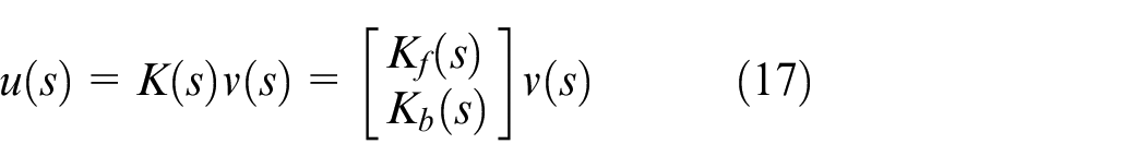
In the two-DOF control, the controller

If all the above equations for all elements in the disturbance set model are established, the controller
The closed-loop transfer function of the system and the reference model
The above equation can be shown as a lower linear fractional transformation form:
According to the compression properties of linear fractional transformation in,
29
when
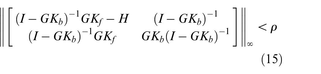
Then
Therefore, when the output disturbance satisfies
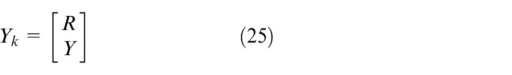
The standard H∞ problem is presented in Figure 8. Where
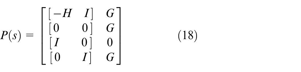

Where q is the output of the model

Structure of standard H∞ problem.
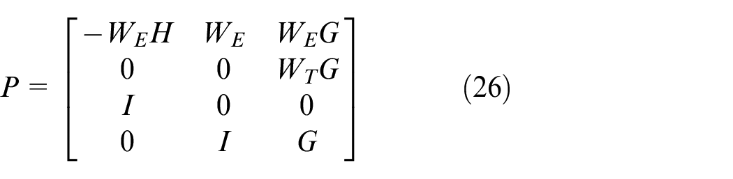
Substituting (15) to (18) into (19), it can be obtained that
For the generalized system presented in Figure 8, the controller

According to the small gain theorem,
30
if
Two-DOF controller design
The solved problem of a two-DOF robust controller according to equation (16) can be expressed as Figure 9.
Schematic diagram for design structure of two-DOF H∞ controller.
The external disturbance of the system is expressed as
Where
The evaluation output of the system is expressed as
Where
Controller input is expressed as
Where
The generalized control object solved by the controller can be expressed as
When the controller is designed as

The closed-loop transfer function of the generalized control model is expressed as
The controller
Thereby ensuring the robustness of the system.
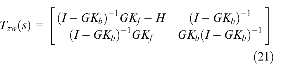
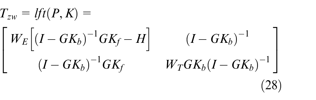
With the previous analysis, it is concluded that the double-loop synchronous loading control system is a two-input and two-output control system, and there is mutual coupling interference among different control channels. The tracking precision of the control system is influenced by the coupling effect of the system. Therefore, when designing the controller, it is necessary to consider the coupling inhibition of the system. The transfer function of the double-loop synchronous loading control system from the instruction to the system tracking output is
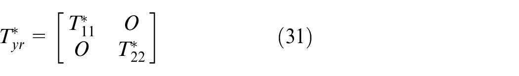
During the design of two-DOF model reference
The goal of controller solution is to minimize

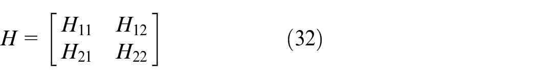
When designing the reference model, it is necessary to set the non-diagonal elements in H to zero to ensure the disturbance attenuation of the system coupling. At the same time, the element
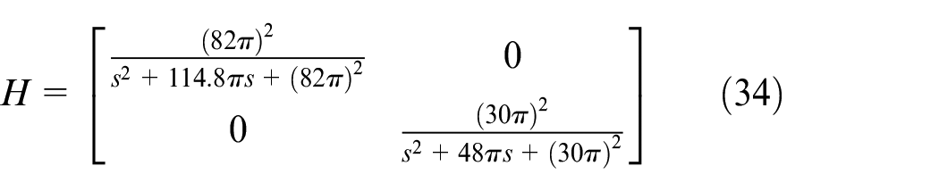
To meet the requirement that the torque loading system has a frequency larger than 40 Hz under the dual-ten condition,
The non-diagonal elements of the reference model H are set to 0, for inhibiting the coupling between the two channels in the control system.
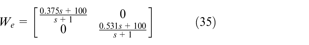
For the selection of weighting function
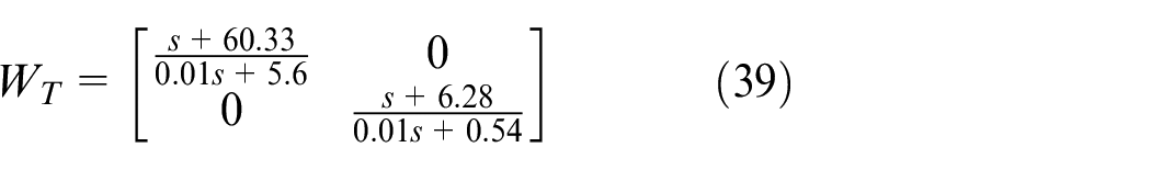
Usually, the inductance, resistance and counter electromotive force of the model in the motor cannot be accurately obtained, and the transformation of these parameters affects the accuracy of the model. When modeling the disturbance, these parameter perturbations are uniformly transformed into the output multiplicative uncertainties of the system. 31


Then

The parameter samples are randomly selected in the parameter disturbance set and substituted into the nominal model of the system to form a system model set with parameter perturbation. All elements in the model are substituted into equation (31), the singular values are calculated, and the curves are drawn, as shown in Figure 10. When calculating the uncertain model, the disturbance range of inductance, resistance and counter electromotive force is ±20%. The weighting function
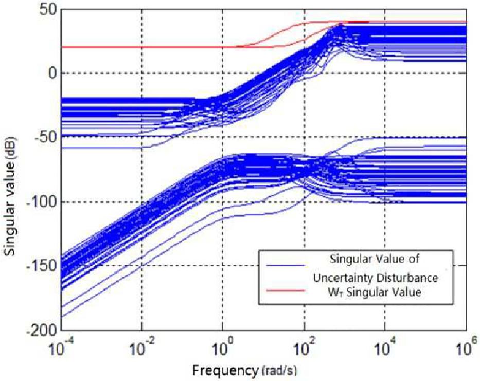
Disturbance range of output multiplicative uncertainty.
Verification of two-DOF H∞ controller
The controller
Figures 11 and 12 show that the position motor in the double-loop synchronous loading system with the two-DOF H∞ controller tracks the angular position of the rudder quickly and accurately, thereby reducing the surplus force caused by the angular position difference between the loading motor and the rudder. Therefore, the torque loop can well track the sinusoidal torque with a frequency of 40 Hz.
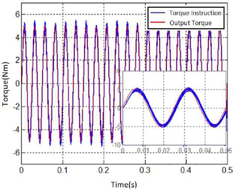
Torque loading response under ±20% parameter perturbation at 40 Hz.
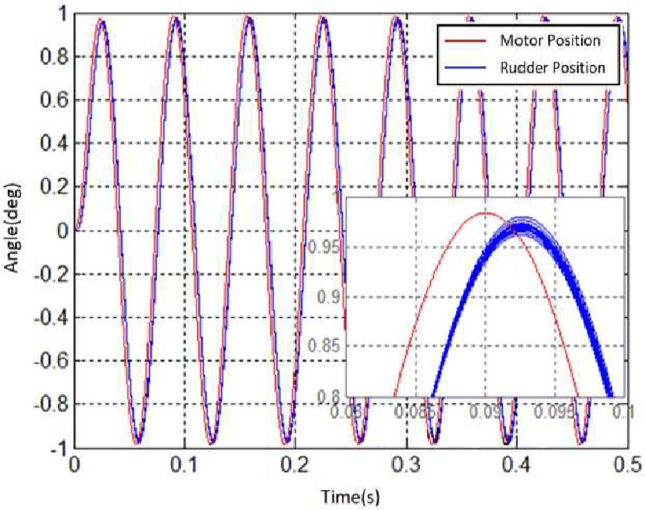
Tracking response of position motor under ±20% parameter perturbation at 40 Hz.
System simulation verification
The digital simulation method is used to compare the designed controller with the traditional composite controller in terms of control stability and torque loading accuracy. The relevant main performance indicators of the loading system are designed as follows:
Maximum loading torque: 60 Nm;
Surplus force suppression ratio: 6%;
Frequency band: Under the rudder disturbance, the loading system should meet following conditions:


Where
Verification of surplus force suppression capability
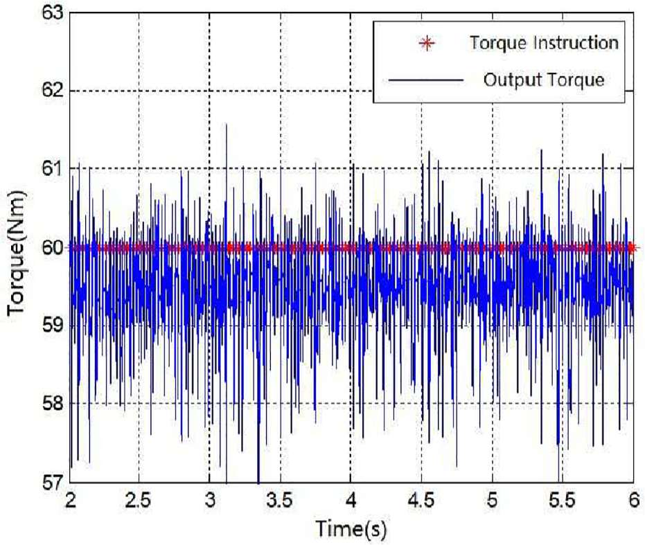
When the torque exerted by the loading system on the output shaft of the rudder is a constant torque, the loading system should be able to effectively overcome the effect of surplus force generated by the movement of the rudder. This surplus force suppression capability allows the output torque to maintain at a stable value.
The simulation is set that the torque instruction is a ramp signal with a maximum value of 60 Nm. Once the loading system applies torque, the rudder keeps a sinusoidal motion with a rudder deflection angle of 1.5° and a frequency of 25 Hz, and then the ability of the two loading modes to suppress the surplus force is examined. The torque loading curve is as shown in Figure 13.
Simulation result diagram of surplus force suppression of the double-loop loading system under the Rudder’s movement condition at 25 Hz.
As a comparison, the loading curve of traditional composite control loading system under the same conditions is shown in Figure 14:
Simulation result diagram of surplus force suppression of the composite control loading system under the Rudder’s movement condition at 25 Hz.
As shown in Figures 13 and 14, when the frequency of the rudder increases upto the limit (i.e. 25 Hz), the influence on the double-loop loading system is relatively small. The main reason is that the double-loop synchronous loading system suppresses the surplus force through the position synchronization loop. The bandwidth of the position motor is larger than that of the rudder, thus the position motor can better follow the position of the rudder for movement and reducing the interference of the rudder movement to the torque loading, and the interference ratio of the surplus force is 5%. On the contrary, when the loading system with composite control is moving at high frequency, the composite control method performs poorly in this case for reasons that the main component of the surplus force is caused by the acceleration speed of the rudder, and that there is no direct observation of the acceleration speed in the system and that the acceleration speed signal obtained by the way of differential and filtering will have noise and phase lags at the same time. The interference ratio of the surplus force is about 30%.
Verification of torque loading frequency band
The torque output should rapidly response the changes of the torque instruction in order to realize the torque loading with a high frequency band. The simulation conditions are set as follows: the torque instruction is sinusoidal, the torque amplitude is 60 Nm with the frequency of 40 Hz, the rudder motion is 1.5° with the frequency of 25 Hz. The simulation results are as shown in Figure 15:
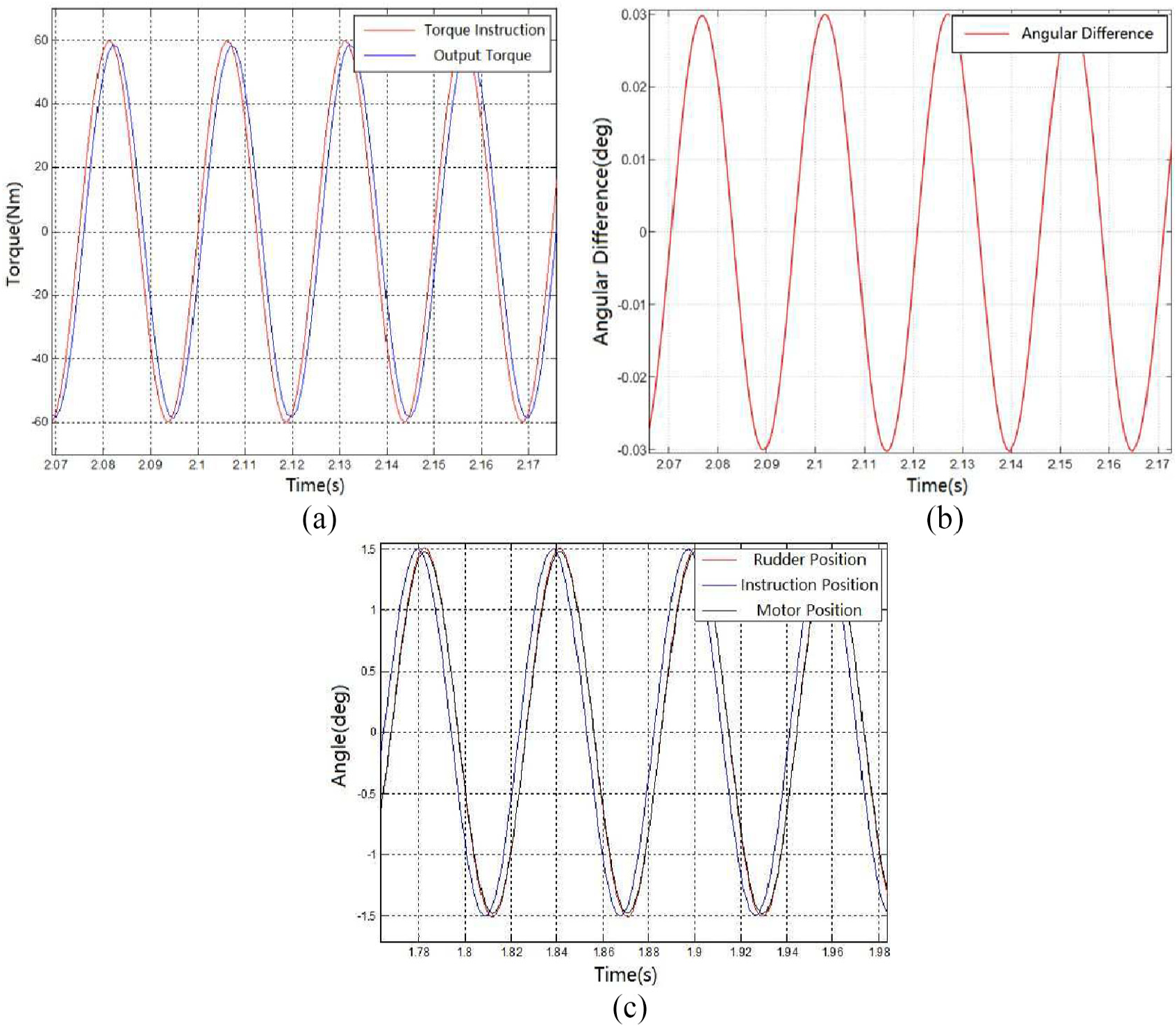
Simulation result diagram with the frequency at 40 Hz: (a) tracking curve of torque output and torque instruction, (b) position difference, and (c) tracking curve of Rudder position and position motor.
It can be seen from Figure 15 that the position motor follows the angle movement of the rudder precisely, with an angular difference of about 0.03°. Under such position synchronous conditions, the torque loading bandwidth can reach 40 Hz. Meanwhile the amplitude difference is 5.8%, with a phase difference of 6.8°. The system meets the dual-ten indicators.
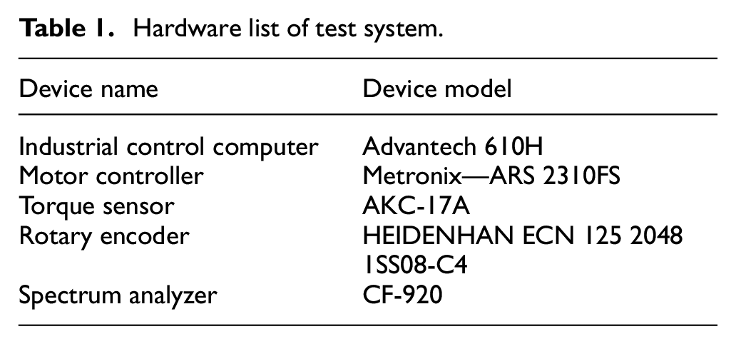
Verification of physical system
The test verification system mainly includes double-loop DC brushless motor, motor controller, spring rod, torque sensor, rotary encoder, analog actuator, analog actuator driver, strain amplifier, industrial control computer, spectrum analyzer, etc. The hardware devices list is shown in Table 1.
Hardware list of test system.
The main components are shown in the Figure 16 and Figure 17.
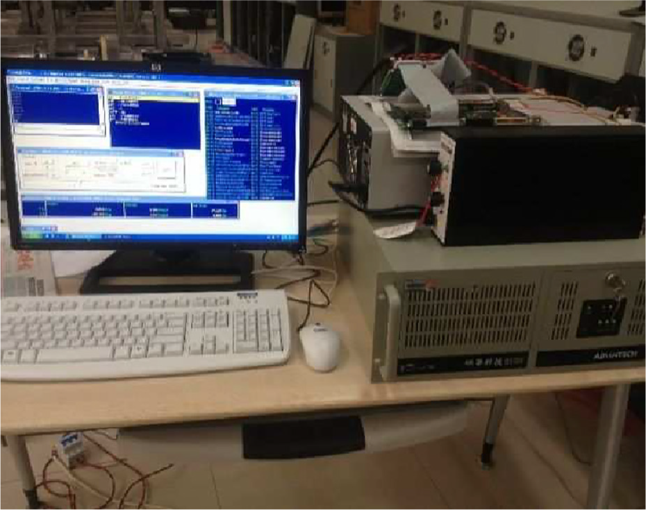
Industrial control computer.
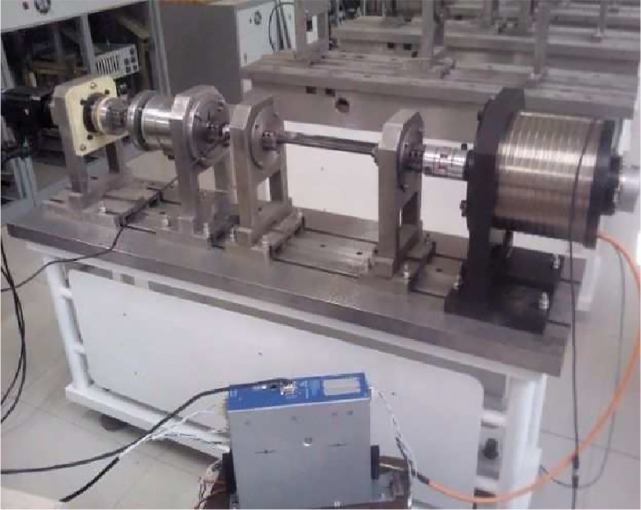
Overall structure of test system.
The loading control software is composed of two parts, in which the user program runs under windows, the real-time control program is based on the Ardence RTX kernel module and developed in C language, with a control period of 0.5 ms. The flow chart of the whole software is shown in Figure 18.
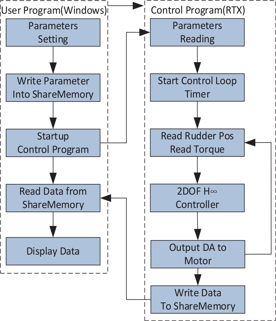
The software flow chart of the double-loop loading system.
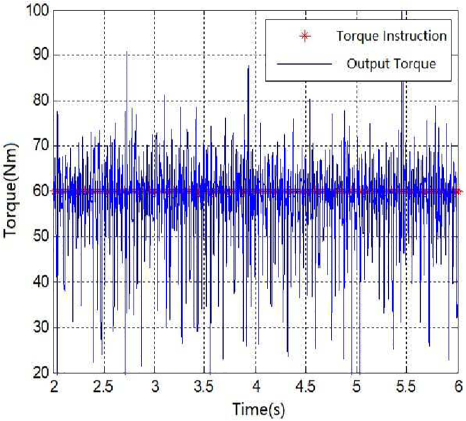
Figure 19 shows the tracking curve of 40 Hz sinusoidal torque command when the rudder is in 10 Hz sinusoidal motion. The curve is acquired by the spectrometer CF-920. The result shows that even the frequency of the torque command is out of sync with the frequency of the rudder motion, the actual load exerted on the rudder is very closely to the command torque. The amplitude difference is 9.31% and the phase difference is 9.6° by FFT analysis.
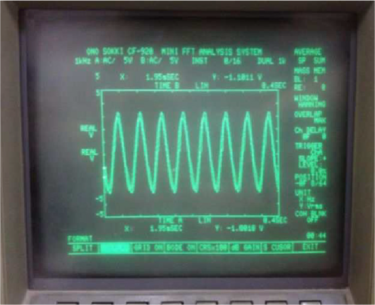
Analyzing result in spectrometer CF-920 with the torque command at 40 Hz.
Conclusion
In order to restrain the surplus force and meet the demand of high frequency band loading application, the paper presents an innovative double-loop loading system design. The simulation results show that the new system with H∞ controller solves the issue of unexpected position disturbance caused by the rudder system, therefore effectively suppresses the influence of the surplus torque. It allows the limit operating frequency band to reach 40 Hz, putting forward a new solution to improve the dynamic frequency response of the system. In engineering, it meets the requirements of the hardware-in-the-loop simulations with high frequency band.
Due to the complex structure of double-loop loading system, nonlinear disturbances such as clearance and friction of the transmission mechanism may affect the loading performance of the system. Later work can focus on the combination of disturbance compensation strategy and existing control strategy.
Footnotes
Declaration of conflicting interests
The author(s) declared no potential conflicts of interest with respect to the research, authorship, and/or publication of this article.
Funding
The author(s) received no financial support for the research, authorship, and/or publication of this article.