
Abstract
The gas turbine aero-engine control systems over the past eight decades have been thoroughly investigated. This review purposes are to present a comprehensive reference for aero-engine control design and development based on a systematic scientometric analysis and to categorize different methods, algorithms, and approaches taken into account to improve the performance and operability of aircraft engines from the first days to present to enable this challenging technology to be adopted by aero-engine manufacturers. Initially, the benefits of the control systems are restated in terms of improved engine efficiency, reduced carbon dioxide emissions, and improved fuel economy. This is followed by a historical coverage of the proposed concepts dating back to 1936. A comprehensive scientometric analysis is then presented to introduce the main milestones in aero-engines control. Possible control strategies and concepts are classified into four distinct phases, including Single input- single output control algorithms, MIN-MAX or Cascade control algorithms, advanced control algorithms, More-electric and electronic control algorithms and critically reviewed. The advantages and disadvantages of milestones are discussed to cover all practical aspects of the review to enable the researchers to identify the current challenges in aircraft engine control systems.
Keywords
Introduction
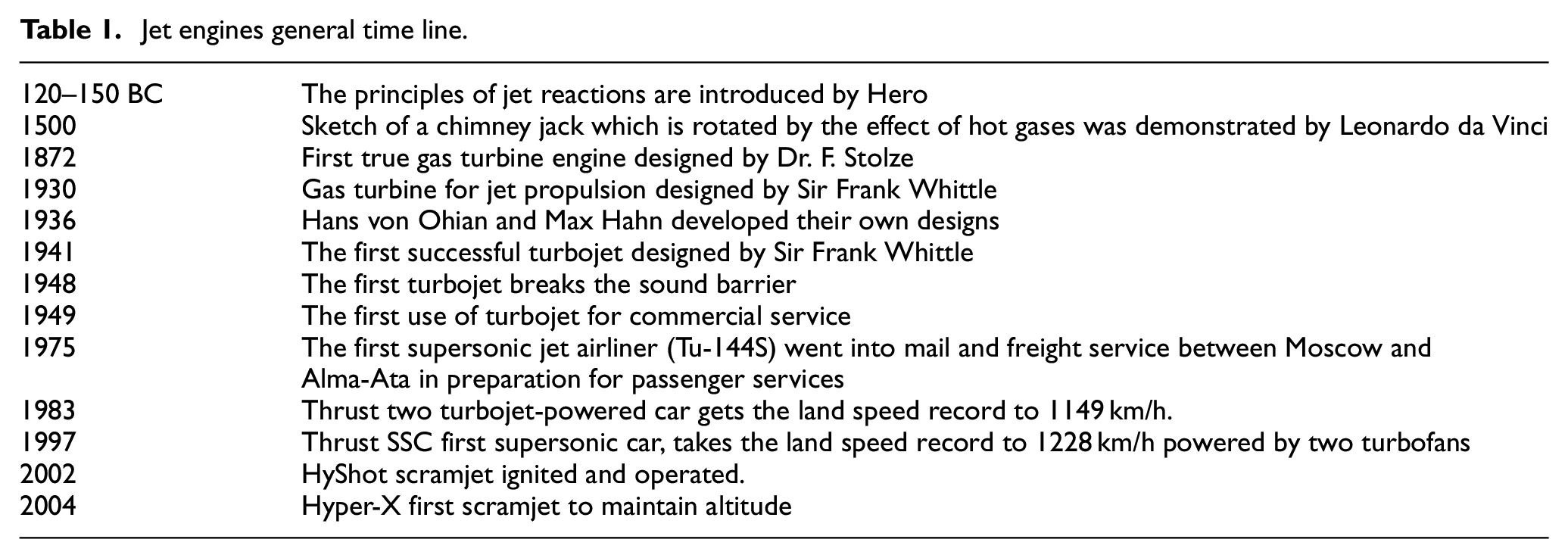
Historically, jet engine invention can be traced back to the aeolipile made around 150 B.C, but today we know Dr. Hans von Ohain and Sir Frank Whittle as two jet engine co-inventors. 1 Van Ohain created a patent for his prototype in 1936, and his jet flew in 1939 for the first time but Whittle’s jet flew in 1941 for the first time. 1
The first jet engines were very noisy like screaming that literally blew ears out which can be contrasted to today heard noise drastically. The main reason of this difference is fundamental design changing over the past six decades, in a typical gas turbine, through compressor path air is sucked, then combusted and exits the engine through the turbine, this turbine also performs power for the compressor. The initial designs of gas turbines had two main problems first was the noise, and the second was efficiency. After a while, scientists found that it is not necessary to combust all sucked air and thus the idea of bypass jet engine appeared. This idea solved two above-mentioned problems. 1 The noise was significantly reduced regarding this fact that now we have a cool layer bypass air that surrounding that hot air coming out of the turbines and efficiency greatly improved as only part of the air received by the fan needed to be mixed with fuel and combusted. These engines called low bypass ratio turbofans. Nowadays demanded thrust increases and in the same way bypass ratios grow and at these turbojet engines most of the air bypassing the core.
While jet engines became more useful many types of them invented and improved and its applications widely increased. In general, all jet engines and gas turbines do the same thing, so these engines all have five important components: an inlet, a compressor, a combustion chamber, and a turbine with a driveshaft running through them. By the end of these similarities, it can be said that different types of engines have other extra components, different ways of inlet performance, possibility to have more than one combustion chamber, and two or more compressors and multiple turbines. Besides that, these engines can have variety and different important purposes and applications. Aerospace engines should be small, light, and quiet as possible while producing maximum power with minimum fuel. Athwart gas turbines used on the ground do not need to be small or light depending on their operational needs, although they certainly still require maximum power and efficiency. Types of jet engines classified in different ways, but one classification is more common than others: Turbojets, turboshafts, turboprops, and turbofans.
The original design of Whittle which is still broadly used in aircraft today was called turbojet. The concept of making turbojet thrust which is the simplest type of jet engines based on a "rocket" jet that moves a plane forward by firing a hot jet of exhaust backward and this fact that the leaving exhausted gas has much more speed than the entering cold air. 2 Following this concept introduces turbojets as general-purpose jet engines that are suitable for small and low-speed airplanes with steady amounts of power all the time.
A turboshaft engine which is drives top huge rotors of the helicopters as an example has many differences from a turbojet. In turboshafts engines, the exhaust gas produces relatively little thrust, while most of its power spend for driving the driveshaft and transmission power to the gearboxes which are running the rotors. Besides helicopters, turboshaft engines can be found in tanks, boats, trains, and also power plants that incorporate gas turbine engines. 2
Turboprop engines typically use in a modern plane that has a propeller. The performance concept of turboprop engines is similar to the turboshafts with this difference that in turboprop engines the turbine spins a propeller on the front instead of powering an overhead rotor. Since planes that are used propeller for producing thrust, they fly with slow speed, and facing less air resistance makes them very suitable use in light and small aircraft like workhorse. Designing turboprops engines couldn’t solve air resistance problem completely which was one reason for developing turbofan engines.
Turbofan engines gather the benefits of turbojets and turboprops that make them more efficient than both and produce thrust force partly by the concepts of turbojets and partly by turboprops. You will find these engines in giant passenger jets which have huge fans mounted on the front. 2 Table 1 shows the main milestones in the design and development of jet engines more detail can be found in. 3
Jet engines general time line.
As applications of jet engines increased from the first decades of its invention the necessity of controller for them appeared. Engine maximum efficiency at each situation is the main goal of any controller. Any pilot desired speed and acceleration (for aero application as an example without loss of generality) must be traced by jet engine and these accelerations and decelerations need to be controlled carefully by a controller. 4
In commercial and military aircraft that use evolved modern dual spool turbofan engines while performance, operating life, reliability, and safety have key characters, controls technology has played a vital role in advancing them. A suitable engine control system based on pilot’s power request must evaluate the required engine fuel for producing that desired power and then enters this determined fuel to the combustion chamber(s) of engine; and finally with respect to the presence of airflow disturbance and flight conditions changing it should maintain the engine power at the desired level. 4 Besides that, each turbojet engine has many control modes that need to be satisfied.
Historically, the development of jet engine controllers can be divided into five main categories as follow: 4
Hydromechanical fuel controllers which still have many applications on different engines were the first controllers used in jet engines, but electronic-based controllers’ appearance made their applications more is limited. Fuel computing and metering to provide suitable engine fuel amount is two sections in this classification. A pure hydromechanical fuel control computing the duel rate with no electronic interface assisting and for engine speed sensing it uses generally driven by the engine gas generator gear. 4 Other mechanical engine parameters that must be sensed in this kind of controllers are exhaust gas temperature (EGT), compressor discharge pressure (CDP), inlet air temperature and pressure, and burner pressure. 4 While the computing section evaluates the correct fuel flow amount, the metering section duty is to deliver the fuel to the engine through cams and servo valves. Hydromechanical fuel controllers have a complicated actual operating procedure and the fuel metering in this system is not as accurate as controllers which are used electronic interface as main system brain for computing.
Hydromechanical/Electronic Fuel Control
The next step in the turbine engine fuel controls was the addition of the electronic control to the basic hydromechanical fuel control. Generally, this type of system for adjusting the fuel flow used a remotely located Electronic Engine Control (EEC). The basic function of the engine fuel system is to pressurize the fuel, meter fuel flow, and deliver atomized fuel to the combustion section of the engine. Fuel flow is controlled by a hydromechanical fuel control assembly, which contains a fuel shutoff section and a fuel metering section. 4
This fuel control unit is sometimes mounted on the vane fuel pump assembly. It provides the power lever connection and the fuel shutoff function. The unit provides mechanical over-speed protection for the gas generator spool during normal (automatic mode) engine operation. In automatic mode, the EEC is in control of metering the fuel. In manual mode, the hydromechanical control takes over. 4
During normal engine operation, a remotely mounted Electronic Fuel Control Unit (EFCU) performs the functions of thrust setting, speed governing and acceleration, and deceleration limiting through EFCU outputs to the fuel control assembly in response to power lever inputs. In the event of electrical or EFCU failure, or at the option of the pilot, the fuel control assembly functions in manual mode to allow engine operation at reduced power under control of the hydromechanical portion of the controller only. 4
Digital Electronic Engine Control (DEEC
The DEEC system which was tested on the NASA F-15 received to control a wide range of engine functions such as inlet guide vanes, compressor stators, bleeds, main burner fuel flow, afterburner flue flow, and exhaust nozzle vanes. 4 Engine input measurements that led to these computer-controlled functions included static pressure at the compressor face, fan and core rotational speed, compressor face temperature, burner pressure, turbine inlet temperature, turbine discharge pressure, throttle position, afterburner fuel flow, fan and compressor speeds, and an ultraviolet detector in the afterburner to check for flame presence. 4 Functions carried out after input data were processed by the DEEC computer included setting the variable vanes, positioning compressor start bleeds, controlling gas-generator and augmentator fuel flows, adjusting the augmentor segment sequence valve, and controlling the exhaust nozzle position. These actions, and others, gave the engine—and the pilot—rapid and stable throttle response, protection from fan and compressor stalls, improved thrust, better performance at high altitudes, and they kept the engine operating within its limits over the full flight envelope.
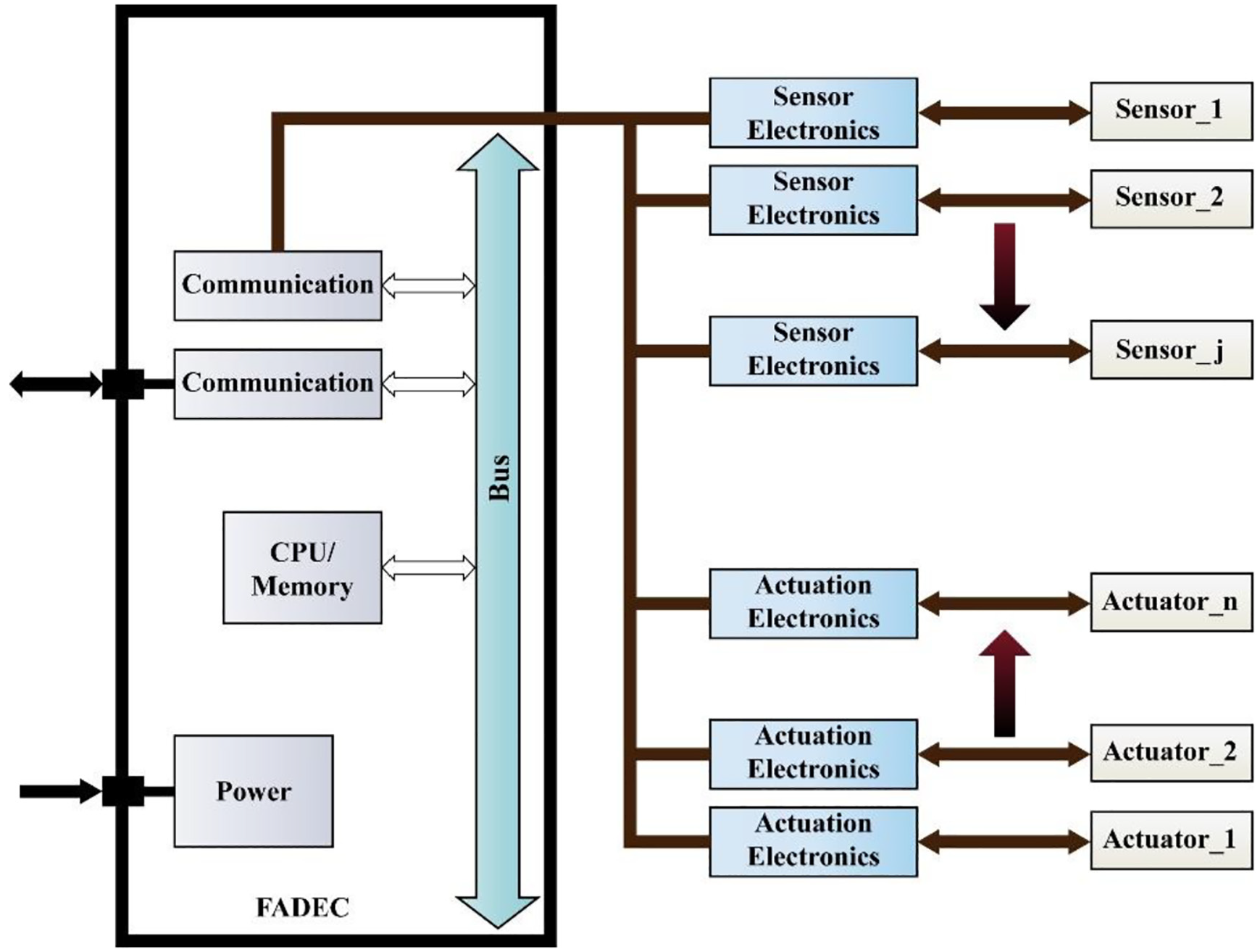
Full Authority Digital Engine (or electronics) Control (FADEC)
True full authority digital engine controls have no form of manual override available, placing full authority over the operating parameters of the engine in the hands of the computer. 4 If a total FADEC failure occurs, the engine fails. If the engine is controlled digitally and electronically but allows for manual override, it is considered solely an EEC or ECU. An EEC, though a component of a FADEC, is not by itself FADEC. When standing alone, the EEC makes all the decisions until the pilot wishes to intervene.
FADEC works by receiving multiple input variables of the current flight condition including air density, throttle lever position, engine temperatures, engine pressures, and many other parameters. 4
Moreover providing efficient operation of engine, FADEC creates engine limitation programming opportunities for manufacturers and can inform them about engine health and maintenance reports. 4
Advanced Engine Control
This category grew considerably during the 1990s with a mass of technology development efforts under Air Force research programs in collaboration with NASA. 4 The goal of these efforts was to apply multi-variable and intelligent control approaches to attain engine improved functionally and performance. Some of the significant accomplishments in the mid-1990s to early 2000s include Integrated flight/propulsion control, 4 Intelligent Life Extending Control, 4 High Stability Engine Control (HISTEC), 4 and Active Stall Control (ASC). 4
In order to go through a historical review of the above-mentioned categories in detail, a scientometric study is firstly done in section two to find the research studies with the highest impacts on the engine control development and optimization. Based on the outcome of the scientometric analysis, an analytical review will be presented in detail.
The main contribution of all the above-mentioned categories is to include control loops to satisfy GTEs steady-state control requirements (to provide the pilot required thrust without any steady-state error), transient-control requirements (to provide the pilot required thrust within an acceptable response time), and physical limitation control requirements (to limit the maximum acceleration, deceleration, turbine inlet temperature, engine shafts rotational speeds, etc.). At any instantaneous time, a pre-defined control strategy selects the appropriate active control loop for the engine. This guarantees to satisfy all engine control modes simultaneously. For this purpose, different architectures, embodiments, and control laws are proposed and implemented in the literature. So, this paper purposes are to present a comprehensive reference for aero-engine control design and development based on a systematic scientometric analysis and to categorize different methods, algorithms, and approaches taken into account to improve the performance and operability of aircraft engines from the first days to present to enable this challenging technology to be adopted by aero-engine manufacturers. A comprehensive bibliometric and scientometric analysis of gas turbine controls including author, publication, reference and citation is presented in section two. It will be followed by a historical review on the progress of the development of gas turbine engine (GTE) control systems for aerospace applications in section three as structured in Figure 1. Finally, the concluding remarks and exploring the future of aero-engine control systems is presented.
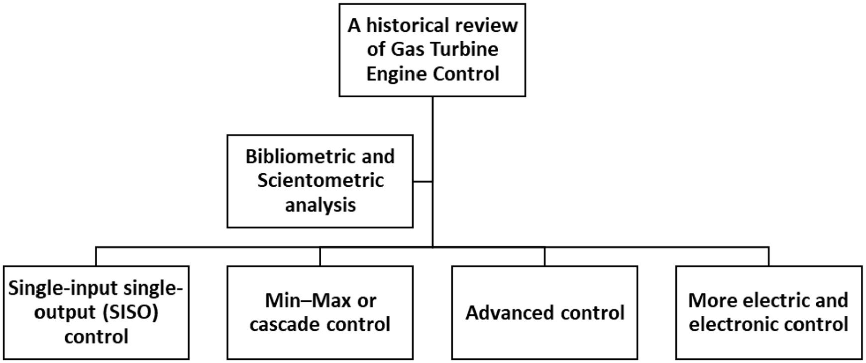
Structure of the historical review.
Bibliometric and scientometric analysis
One of the areas that have been created in last decades based on the science evolution is scientometrics. Today, scientometrics has its own assessment methods in scientific investigations and research management. 5 Fast information growth and its variation have been caused to huge data rush for scientometrics as a research field. 6 With respect to the above-mentioned reasons it’s necessary to design a scientometric process for investigating researches that have been done.
The main indices of scientometrics are categorized by Franceschet in 2009 as follow: 7
Productivity metrics: this index includes the number of papers/publications, the ratio of the number of papers to the track records (in terms of time or number), the ratio of the number of publications to the number of researchers, the number of publications in high-profile journals, etc.
Impact metrics: this index is more focused on the quality; and includes the number of citations, the ratio of the number of citations to the age of the paper, and the ratio of the number of citations to the number of publications.
Hybrid metrics: this index is to combine the above-mentioned indices and to introduce unique numbers which consider both productivity and impact criteria (e.g. g index, h index, individual H index, m quotient, etc.)
The basis of scientometrics is the investigation of four basic variables including author, publication, reference and citation. Scientometric study aims to reveal the characteristics of science and scientific research by separately examining these variables and by an appropriate combination of indicators based on these variables. 8 The number of authors as one of the indicators of scientific activity in different countries can be used as a basis for comparing them. Publications can include all communications and correspondences that have been scientifically published.9,10 Articles publication is one of the main and official paths, which can examine their distribution in terms of time, place, type or channel of publication and other features. The number of publications is an essential element in scientometics that can serve as a basis for comparisons between different communities and countries. Today, most publications are the best media for demonstrating the collective efforts of a number of authors. Since publishing the scientists’ efforts individually is not enough for declaring important statistical results, scientomitric evaluations usually emphasize the usefulness of publication by scientific communities. Research groups, academic departments, scientific institutions, geopolitical countries and regions, and main and sub-scientific areas are exemplary of some of these scientific communities.
Scientists are constantly trying to represent qualities in terms of quantities that represent quality. These quantitative criteria are known as “indexes.” The importance of indexes is to: evaluate performance, influence, rank, compare and promote individuals in the academic environment. Scientometrics does not rely solely on articles; other resources such as books, patent applications, theses, industrial reports, and so on can be the basis of scientometric studies. In this study, these criteria are categorized and evaluated in two general indexes: (1) productivity index and (2) citation index.
Productivity index
Scientific outputs evaluation by counting the number of produced scientific papers is the simplest and most primitive index for measuring the performance of scientists, organizations, and countries. In the productivity index, the number of produced articles by scientists, organizations, universities, etc. is examined over a specific period. The number of produced documents in this article is indicated by the word “Records.”
Citation index
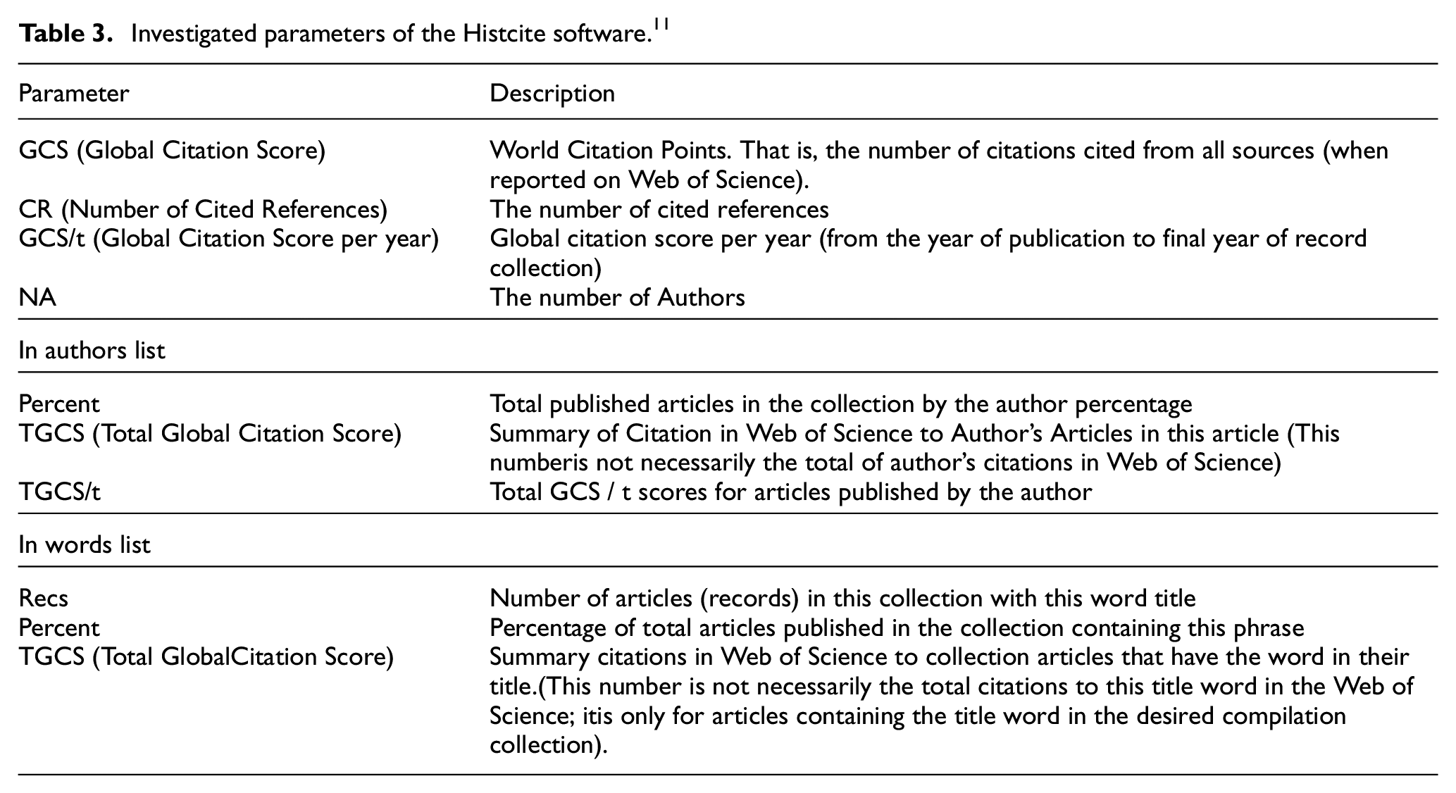
The number of received citations is evaluated In the Citation Index. Unlike the productivity index, which investigates the scientific output quantities, the citation index seeks to evaluate the quality of scientific output. Whenever a large number of activities cite a specific document, it is considered important and credible. The citation index in this article is examined with the term “GCS” which is the number of citations cited from all sources.
The three most important uses of citation analysis that are more accessible through citation profiles are:
Quantitative and Qualitative Evaluation of Scientists, Publications and Institutions: Citation analysis methods can be used to estimate the number of scientific works and to raise awareness of the quality of scientific resources produced by scientists and institutes.
Studying the historical development of science and technology: Using the information obtained from citation analysis, it is possible to study history of science and technology in a particular field and its evolution over time.
Information Search and Evaluation: Citation analysis can be used to map the structure of scientific disciplines as well as identify emerging disciplines. In fact, citation analysis enables the study of interdisciplinary relationships by studying the relationships between journals.
One of the scientometric software which is used in this research is “HistCite.” Histcite is a software that developed by the Eugene Garfield Research Team at Thomson Reuters Institute for the data analysis in research, using both scientometric and bibliometric methods. 11 This software enables researchers who are interested in the extent of production in a particular field of science to map the structure of various subjects. And using the Web of Science (WoS) citation database are provided valuable results in the form of tables with multiple indices to the researchers. So, this software helps researchers to have an analysis of previous research related to their field of study and to identify which authors, organizations, and countries have the most and the highest quality output based on citing.
Methodology
Research methodology of this paper has been implemented in three stages:
In the first step, the WoS (Web of Science) citation database is selected as the information source and the desired data is collected. At this point, term searches with “AND” and “OR” operators have been designed and applied in order to optimally and thoroughly search the topic of this research in the selected database. The result of this step is a large amount of data that has been gathered on the abovementioned subject.
Since the WOS database search engine is based on artificial intelligence much of this gathered data is irrelevant. In the second stage, human monitoring and evaluation were performed on the obtained data and its irrelevant data were separated.
In the third step, the refined data were entered the Histcite and various analyzes were performed on them. The results of these analyzes are presented based on two indices of productivity and citation in the next section.
Table 2 shows some part of the Histcite parameters. These parameters have been used for quantitative and qualitative comparisons in the following section. The aims of this section are:
Control of aero gas turbines area scientometric analysis
Selection of some articles in the studying field to review them in the next section.
Survey data information in the Histcite software.
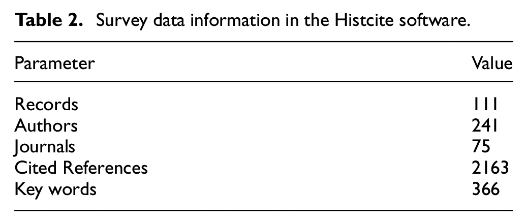
In Table 2, scientometric survey data in the Histcite are shown. As shown in Table 2, the number of articles reviewed in scientometrics is 111,12–122 although the number of references in this article is more than 150. This is because some articles are not available in the WOS database and some of them are not related to the subject of this paper, and WOS outputs were used as Histcite Inputs, so some articles are not included in the scientometric analysis.
The H index is a symbol that measures both the productivity and the scientific impact of a scientist. The H index is based on a scientist’s articles with the most cited and the number of citations they have received. A scientist who has h index has published h papers with a minimum h citation. The Histcite provides a statistical index called the H index, which is based on a set of citation data in this article. The GCS parameter described in Table 3 is the H index based on the global citation scores when the set was created. It should be noted that this index may not be the same as the author’s H index calculated on the WoS site, as it only includes downloaded author’s articles and not all articles published by the author.
Investigated parameters of the Histcite software. 11
The data set collected in this paper is examined in different categories in terms of both productivity and citation indices. These categories include articles, authors, journals, publication trends, citation references, words, types of documentation, institutions, and countries which are explained as follows.
Performance analysis results
Articles
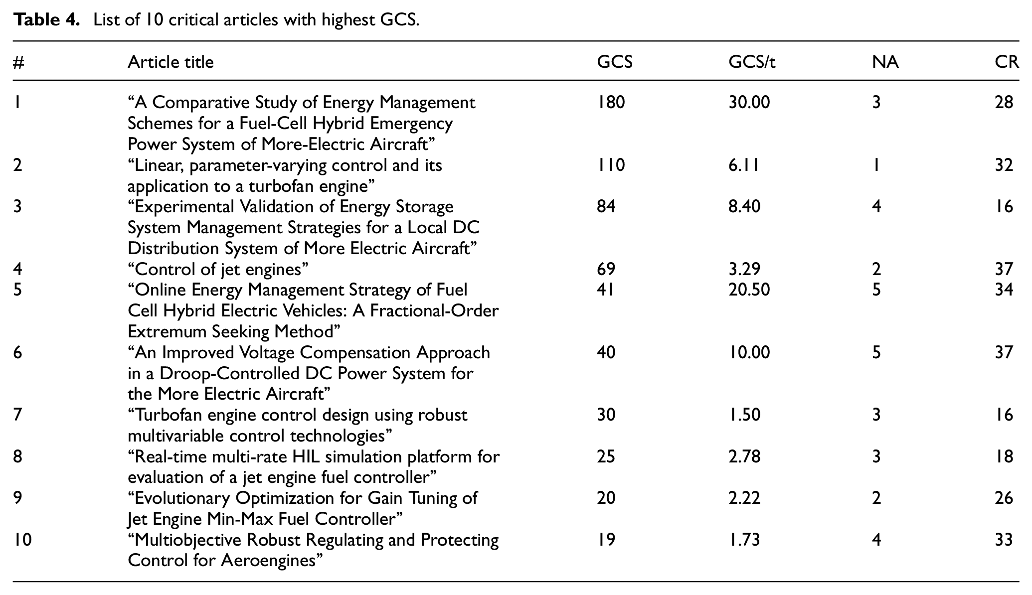
In Table 4, a list of 10 critical articles with the highest GCS is shown. In other words, these papers have the highest global citation score. That is the number of citations cited from all sources (when reported on Web of Science). This indicates the quality of the method and results of the research done in the articles. From this table, one can find investigations trend and valuable research topics and issues in the field of control of aero gas turbine engines, including Energy-Management Research on More-Electric Aircraft and Hybrid Electric Vehicles—Robust multivariable control research, etc.
List of 10 critical articles with highest GCS.
Publication trend
According to Figure 2, there are 22 articles in 2019, 13 in 2018, and 9 in 2017 that were published. In other words, about 40% of the articles on aero gas turbine engine control in the collection compiled in this article (111 articles) have been published in these 3 years. This reflects the attention of researchers to the field of aero-engine control in recent years. Figure 3 shows the TGCS parameter per year developed by HistCite in descending order. The sum of citations to articles published in 2014, 2010 and 2011 is the highest. In these years, the highest quality work has been published by researchers.
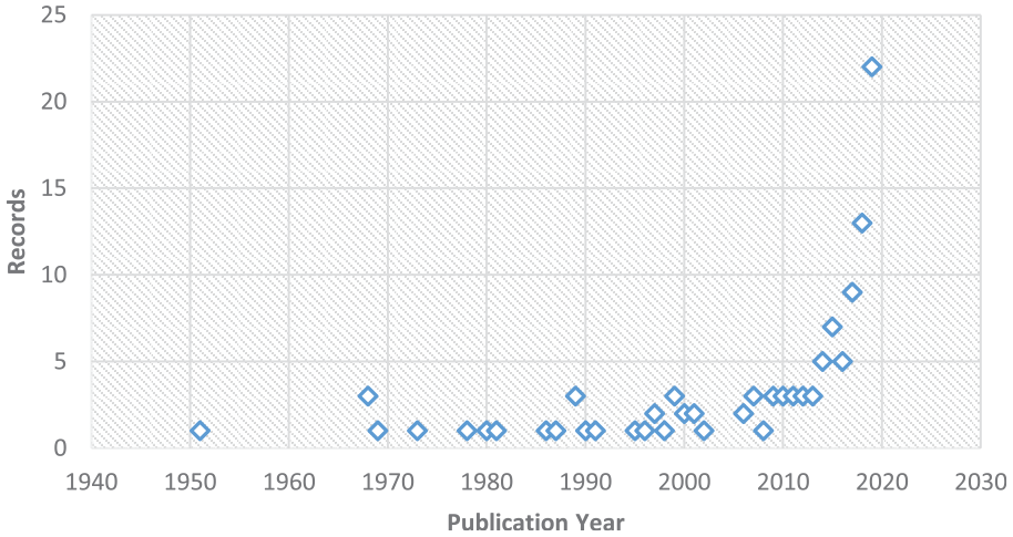
Number of records based on year.
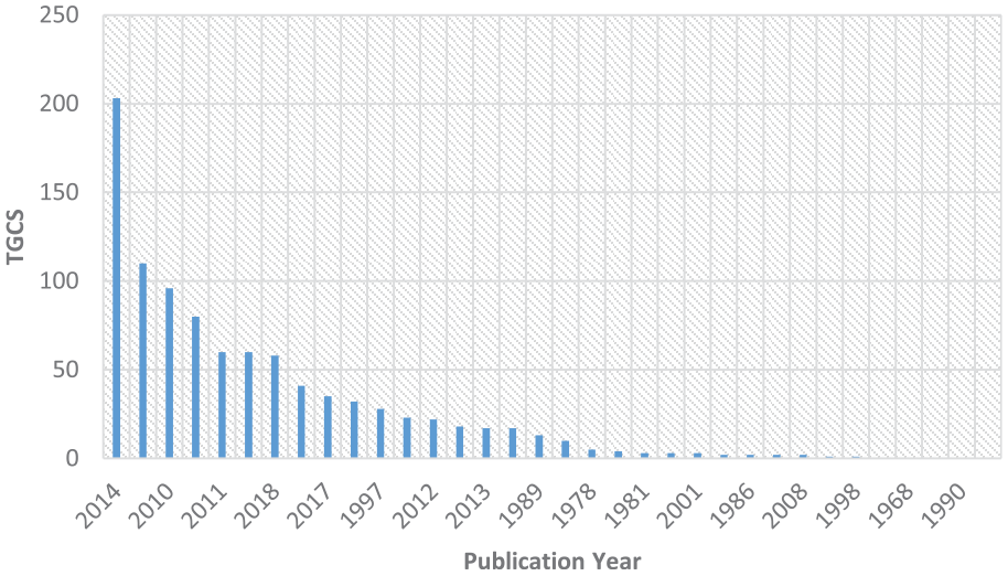
TGCS parameter based on the year.
Authors
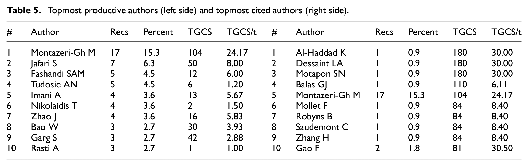
Table 5 lists the top 10 most productive authors (left table) and the top 10 most cited authors (right table). In recent years the most prolific writers (Most Records) have been introduced as Montazeri-Gh, Jafari, and Miran Fashandi respectively. But on the list of most-cited authors (most TGCS) are El Haddad, Desinet, and Motafone. From these tables, one can identify top productive authors and cited researchers and by following their research process, one is able to reach high-quality, potential research topics and, in some cases, foresight science in a specific research area.
Topmost productive authors (left side) and topmost cited authors (right side).
Countries
Figure 4 shows the number of records for each country. According to this figure, the number of articles has the highest value for the four countries (topmost productive countries) China, America, Iran, and Britain. Figure 5 shows the TGCS parameters for each country (most cited countries). This parameter is the highest for the US, Canada, France, and Iran.
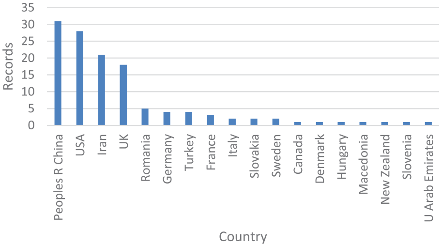
Most productive countries (most records).
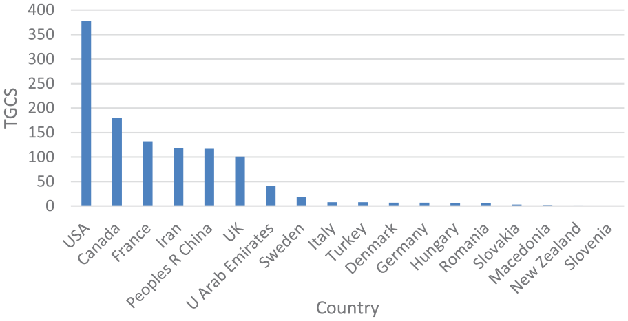
Most cited countries (most TGCS).
Journals
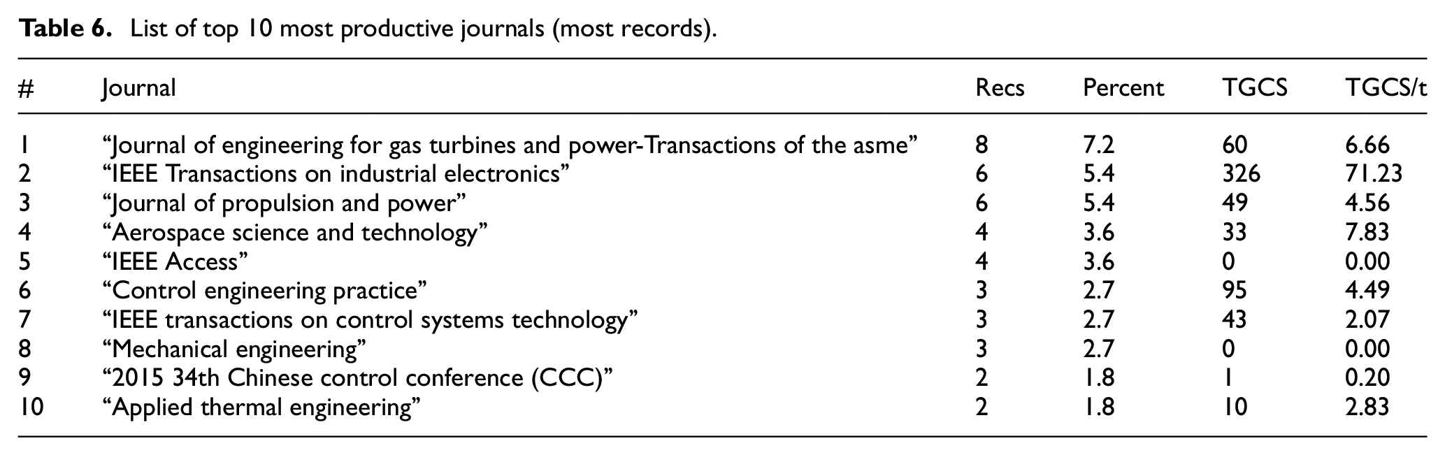
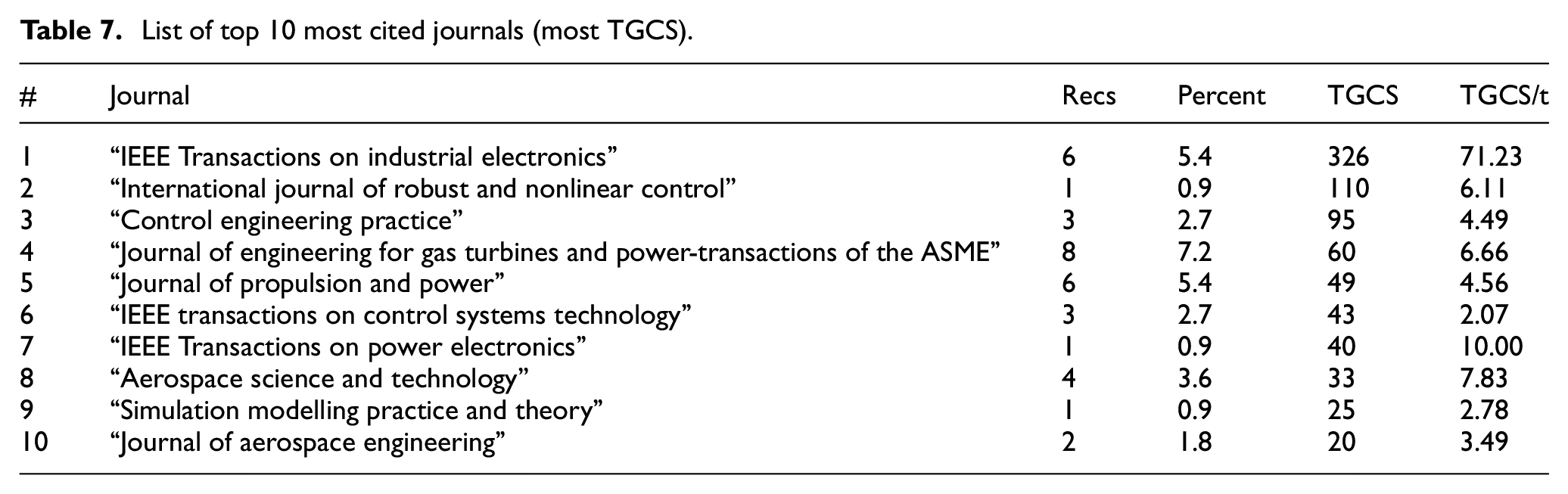
Table 6 lists the top 10 most productive journals (most records) and Table 7 lists the top 10 most cited journals (most TGCS).
List of top 10 most productive journals (most records).
List of top 10 most cited journals (most TGCS).
Documentation type
Figure 6 illustrates the types of documentation in scientometric studies. As can be seen in the figure, about 64% of the papers in this study are article type, and about 27% are proceedings paper type. The other 9% are Book chapter, Meeting abstract, Note, etc.
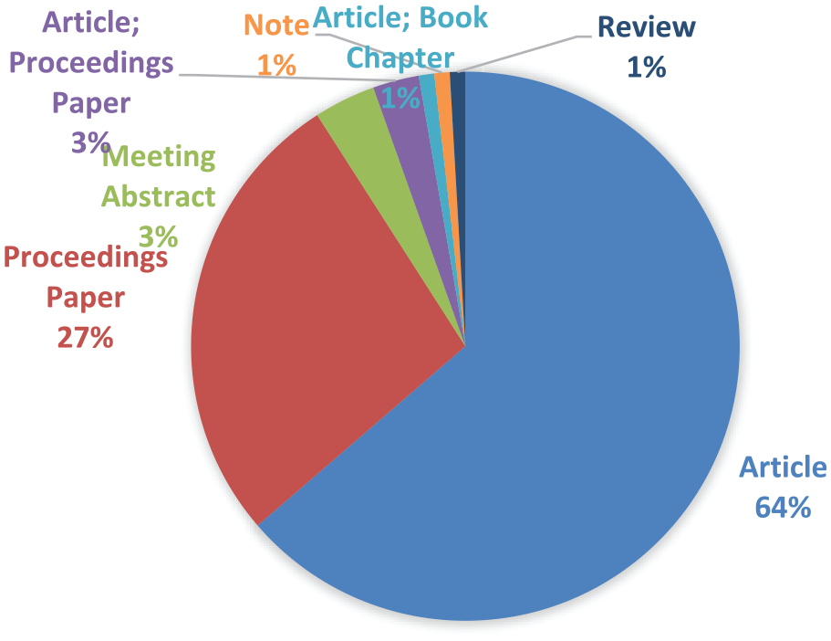
Type of documentation.
Institutions
Figure 7 shows the list of institutions with most records (most productive) and Figure 8 shows the list of institutions with most TGCS (most cited).
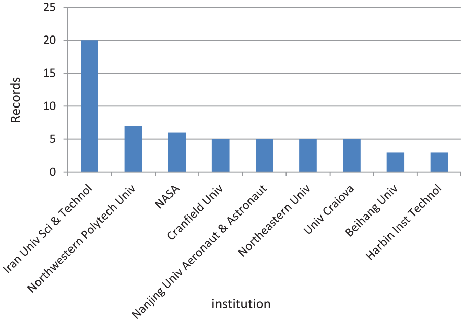
List of most productive institutions (most records).
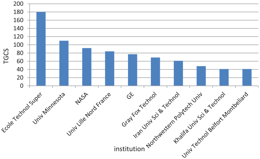
List of most cited institutions (most TGCS).
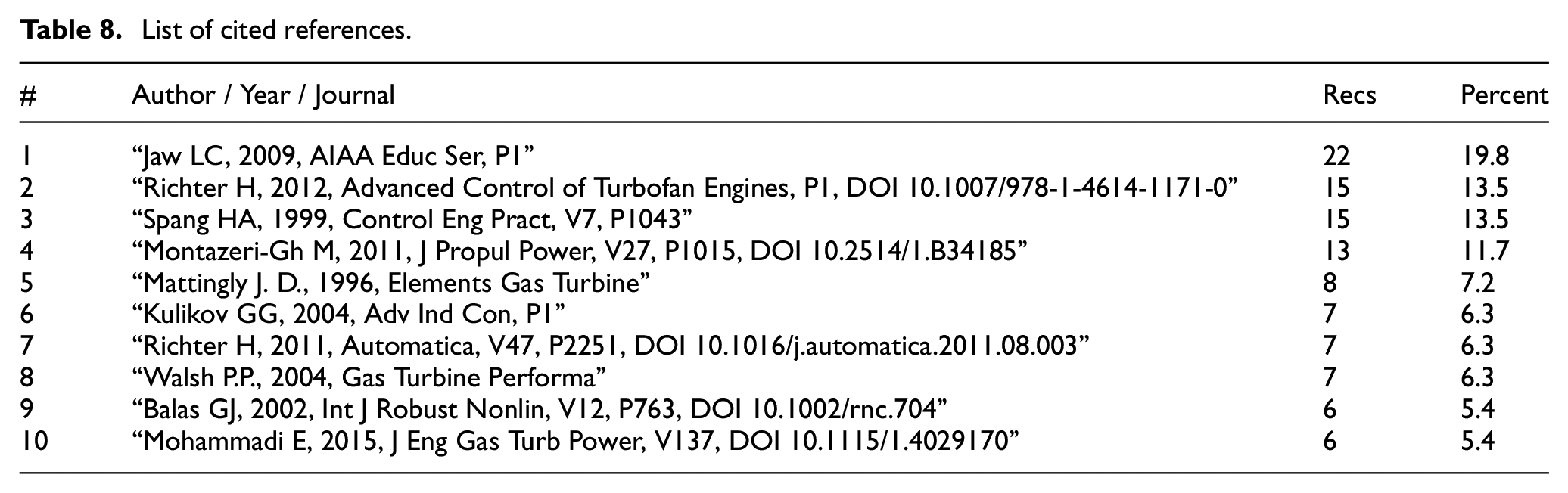
Cited references
Table 8 is important in order to show articles in our collection that are more cited and to identify articles that have been documented but not in our collection. In Table 8, “Recs” means the number of records that cited this reference. The Histcite can retrieve the references used in the retrieved articles and show which ones exist in the retrieved collection and which ones were not retrieved, or not present in the WoS database. This reveals the specific features of any document that are associated with our subject and aren’t in the WoS database. This allows one to access vast related documents outside the WoS database. Blue records (records 3 and 9 in Table 8) are part of the set, but black records (others except records 3 and 9 in the Table 8) not included (not subject to search criteria in WoS or not listed in WoS). It should be mentioned that some of the black document references are either books not listed in WoS or articles that do not include keywords in their title. That article, although it was lost in the search, may have been repeatedly cited and thus relevant to the topic.
List of cited references.
Keywords
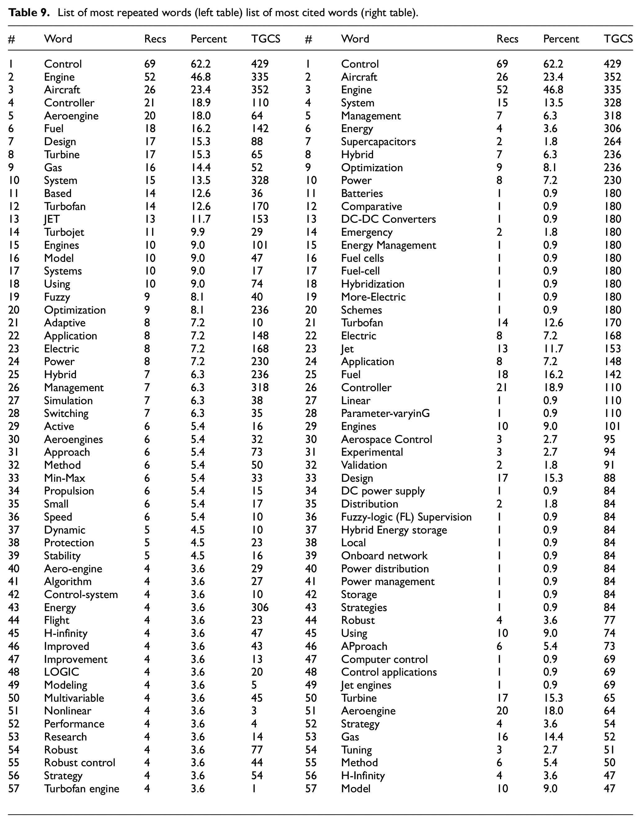
Table 9 investigates the words in the titles and keywords of the collected articles. This table shows the most repeated word (most records) list (left table) and the most cited word (most TGCS) list (right table). In this table, repeat words with a repetition limit of at least four times and citation words with a limit of TGCS citation rating of at least 47 are selected. One can cluster the vocabulary of this collection and display it in separate tables, from which one can find research trends and related or most repeated or most cited topics.
List of most repeated words (left table) list of most cited words (right table).
Thanks to the invaluable sources found from the scientometric analysis, the following section will analytically review the milestones in the field of gas turbine engines control.
A historical review of gas turbine engine control
As said previously, jet engine controllers over time have changed in two main areas: their hardware and the concept of control have both been investigated in many studies, which are introduced in the following chapter.
The historical progress of the development of gas turbine engine (GTE) control systems for aerospace applications could be divided into four phases:
- Single-input single-output (SISO) control algorithm
- Min–Max or cascade control algorithm
- Advanced control algorithm
- More electric and electronic control algorithm
During this period much research was carried out at scientific centers, two of them being General Electric and NASA. 112 They are the first type of time controller and are briefly discussed below in A-1 and, subsequently, the most important developments from this era are dwelt upon in sections A-2 to A-7.
(A-1) J47 was the name of the first afterburning turbojet engine in the world which was tested by General Electric (GE). This turbojet engine for the main combustion chamber used a hydro-mechanical fuel control and for the afterburner used an electronic fuel controller. Engine altitude testing performed at the Global Research Center. 112
The main controller achievements were:
Model Simplification do to Calculating Corrected Parameters
Cycle calculations which were done by using slide rule/desk calculators led to obtain engine steady-state performance
Developing “corrected parameters” concept by NASA engineers
Reducing the time consuming for developing the engine steady-state performance model considerably
The concept of corrected parameters is still being used for engine analysis and simulation
Simplified Dynamic Model of Engine Response
The first study on the single-shaft turbojet dynamic behavior
The outcome of this study was to represent the first-order lag linear system for the transfer function from the fuel flow to engine speed and by this achievement the required time to design and validate control logic considerably reduced.
Use of Computers for Real-time Dynamic Engine Modeling
While engines became more complex, control logic evaluating and designing became too complicated
Performing closed-loop method that was integrated control logic with the engine model for dynamic simulation by the Glenn Research Center (GRC)
Use of analog computers for simulation
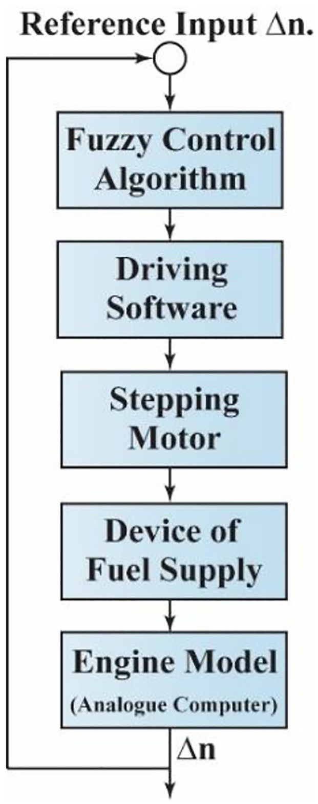
(A-2) In 1951 Seymour C. Himmel et al. published a paper in the “Journal of the Aeronautical Sciences” investigating “the effect of changes in altitude on the controlled behavior of a gas turbine engine.” This paper merely suggested some mathematical equations for calculating fuel flow based on flight situation, had no hardware implementation, and all its results came from simulation. 113
The paper presented a comprehensive analysis with some experimental data to support the altitude-based engine response theory. By introducing the generated data authors showed that the measurements made at sea level could be used for response of the engine at any altitude.
It suggested some equations for describing the dynamic behavior of a turbine-propeller engine while providing its performance with changes in altitude.
The control diagram of its investigated engine can be seen in the below figure:
The conclusion of this article has been obtained from the turbine-propeller engine; while, the authors claimed that introducing this approach for any gas turbine engine for gaining basic results can be applied.
(A-3) In 1956 Watson outlined a fuel control system for gas turbine engines in the James Clayton Lecture. 114 A brief explanation of his controller is as follows:
Watson introduced the idea that engine fuel was required in both steady and transient situations as a function of intake pressure, intake temperature, and engine rotational speed and expanded this function during acceleration and deceleration, illustrating his point with some graphs dependent on this function.
He chose a fuel pump from a variety of different pumps for injecting fuel into the combustion chamber. This decision was based on engine requirements, such as pressure and having a rotational part rather than reciprocating. Besides this, he used a servo system to control pump output.
This control system had pressure, flow, proportional flow, acceleration, rotational speed, electric speed, and, finally, temperature system controls, which had been mounted on the engine very carefully and tested correctly. It is worth mentioning that all this was manufactured by his team.
Printed graphs highlighted some problems, like damping and surge, which were not a major problem at the time, as well as the main problems faced. These included supplying appropriate fuel amount to the combustion chamber at the required pressure under all operating conditions, during a steady-state and under rapid transient in acceleration and deceleration modes. Consuming the maximum possible amount of fuel in a defined situation for ensuring immediate ignition at the starting point and also under critical issues like engine shut down in high altitude, were also problems addressed. Other issues were combustion, turbulence, the presentation of fuel to air, direction of fuel entry, and the ignition problem.
Using the hardware implementation view, this controller belongs to the hydromechanical controller category.
(A-4) During the 1960s, Johnson put forward much scientific research dealing with a fluidic control system for gas turbine engines, which was mentioned in a NASA survey of contributions to fluidic systems 115 as Figure 9. The study with the most citation, entitled “Development of Fluidic Controls for Advanced Integrated Propulsion Systems,” was published in 1968. 116
For providing improved control modes, turbine inlet temperature control and measurement fluidic propulsion controls were developed. This development caused better engine protection, improved performance, and longer engine life by controlling the actual engine conditions.
Johnson mentioned that the next propulsion controller generation must withstand temperatures greater than 1200 F or be penalized by the interconnections to remote cooled locations or weight of local cooling units. Specific objectives performed to attain these aims were:
To respond measured engine condition, he introduced the use of closed-loop acceleration controls.
Respecting to this fact that pure fluidic elements are more simple, lighter in weight, and reliable than conventional controls, he demonstrated the use of these elements, which also withstand 1200 F ambient temperatures and operate on engine compressor air.
To coordinate the function of the exhaust nozzle and engine-inlet and avoid undesired interaction he integrated them.
Control approaches of his study: (1) mode select control for proportional temperature limiting loop; (2) designing a bang-bang control for reducing fuel flow whenever the temperature limit was reached;
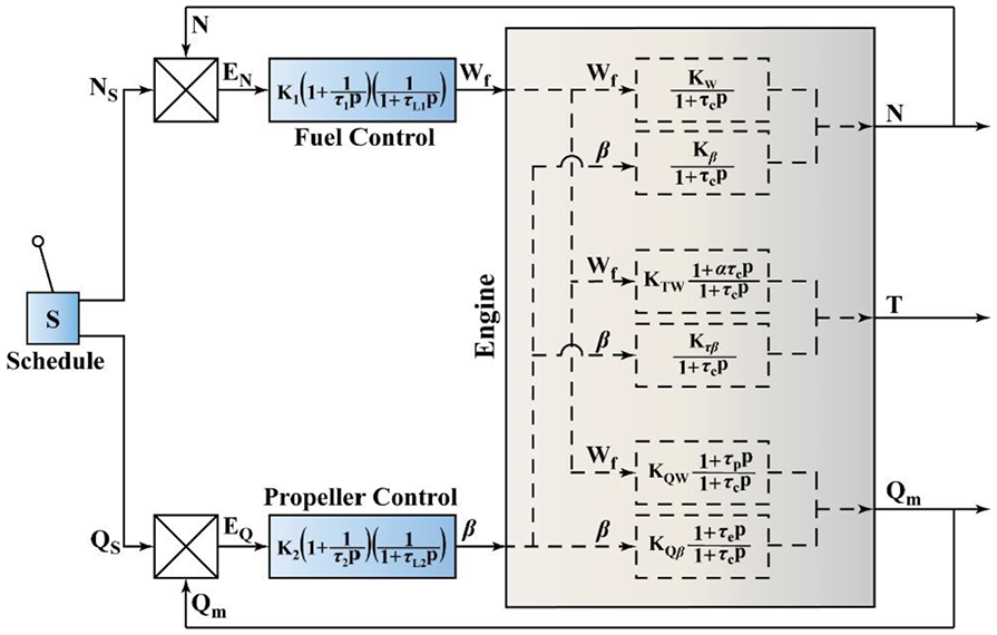
Engine control combination schematic diagram adapted from. 113
Block diagram of fluidic controller adapted from. 116
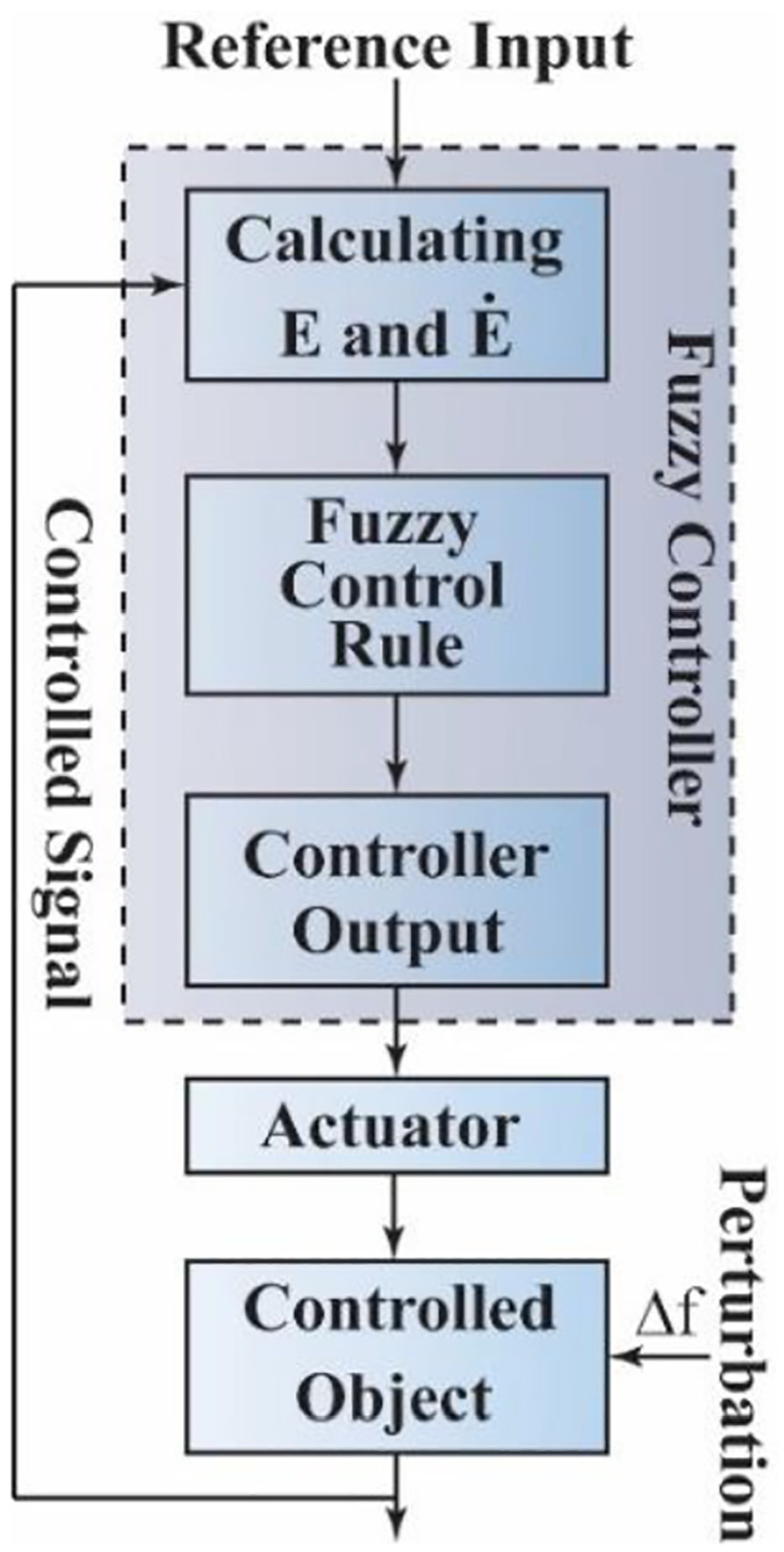
Principals of the fuzzy controller adapted from. 127 .
(A-5) In 1968 Bayati et al. published a paper entitled “DIGATEC” and presented the basic electronic digital computer operating principles for the gas turbine engine control system. 117
This was one of the first attempts using a computer for jet engine fuel flow control. The authors declared that a digital computer is a tool through which an integrated propulsion system may be centrally organized. Accurate modeling of complex mathematical functions and rapid communication between subsystems are the basic characteristics of a computer control system. This paper covered two aspects of implementation—electrical and mechanical.
By linear sample data techniques and combined analog/digital nonlinear real-time simulation study, the selected control modes were programmed and evaluated.
Two main control modes for speed control were investigated using block diagrams and simulation:
Rate-Proportional-Integral Speed Control
Integral Compensation on Engine Acceleration Error
These two modes were implemented as closed-loop models.
The most important thing about this achievement on paper was the use of mixed SISO concepts and Min-Max theory for controlling closed-loop modes.
(A-6) In 1968 Keck et al. described an advanced adaptive fuel control strategy that was successfully developed and tested. The main goal of this development was to attain engine best performance without control adjustment when fuels wide varieties are used, as well as operation with unfiltered contaminated fuel. 118
Keck et al. declared that this suggested method could solve two main problems associated with engine fuel control. The first was fuel contamination and the second was the often-required power-trim adjustment for fuel supply variation in type and quality.
They used four inquiries that were normally encountered for a single shaft turboprop engine: (a) a maximum fuel schedule for over-temperature protection and surge; (b) for combustion blowout protection considering a minimum fuel schedule; (c) for fixed-pitch propeller operation considering a fuel governor; (d) for establishing the desired power level determining a PLA-modulated fuel schedule.
They showed that this survey appears several areas of improvement which should be considered for future design and introduced two of the main areas as follow: (a) for the adaptive parameter they declared the use of turbine inlet temperature, and (b) for the number of parts required, a redesign of the computer section mechanization is needed.
(A-7) In 1969 Evans proposed “control concepts for the high bypass aircraft turbofan engine,” implementing a powerful control system with high maintainability and reliability, low cost, and lightweight. 119
The main control requirements that were achieved using its supporting controller:
The relationship between the power lever angle and engine thrust was linearized.
Once the controller has metered the desired speed the controller holds this computed amount constant.
The maximum range of acceleration and deceleration was controlled based on the function of compressor inlet temperature and discharge pressure and also core rotor speed.
The maximum rate of fuel flow change was limited during acceleration and deceleration and the maximum and minimum accessible fuel flows were defined.
The variable compressor stator vane angle was controlled.
Bringing certain adjustments:
Rotor speed setting for ground idle
Rotor speed setting for Takeoff
The engine variables steady-state position
This period witnessed the birth of multivariable engine control, digital electronic control, and Min-Max theory, and was the era of the maturation of turbine engine control. In the first part of this section (B-1), NASA controllers are explained. This is followed by a brief introduction to all the major research carried out in the field of controller design for jet engines (B-2 to B-8).
(B-1) All NASA collaborations with other companies regarding controller design and manufacture have been separated into two categories and their characteristics are described below. 112
(B-1-1) Digital Electronic Engine Control (DEEC)
In the early 1980s, DEEC was tested on F-100 engine by NASA, in collaboration with USAF and P&W and the result of this test showed the main DEEC benefits as follow: faster response time, increased thrust, afterburner performance and air start improvement, and hardware simplification
The nozzle stability resolution and verification of a faster augmentor transient capability was achieved by testing at the GRC altitude test facility.
The introduction of Electronic Engine Control was defined by flight testing at the Dryden Flight Research Center (DFRC; now AFRC)
DEEC testing by NASA was a vital step which leading to current full authority digital electronic controls (FADECs)
(B-1-2) Multivariable Engine Control Development
The applicability of emerging linear quadratic regulator (LQR) and optimal control theory for jet engines was investigated by Air Force Wright Aeronautical Laboratories and NASA-Lewis
A series of LQRs connected with several operating limits and simple transition logic was developed by The GRC to attain considerably effective transient controls
(B-2) In 1978 Taiwo outlined “design a multivariable controller for a high-order turbofan engine model by Zakian’s method of inequalities,” paper. All its achievements mentioned as follows. 120
For the net thrust level regulation, inlet temperature, and total airflow, a simple multivariable controller based on the method of inequalities was designed considering the F100 turbofan engine and actuators.
The method of inequalities was explained in detail, and all the computation required was performed automatically using interactive software.
The closed-loop controller was performed and it was shown that their method compared favorably with other multivariable design methods.
(B-3) In 1979 Merrill et al. performed “identification and dual adaptive control of a turbojet engine.” The main aim was to realize a “dual-adaptive” feedback control unit for a highly nonlinear twin-spool air-breathing turbojet engine. The outcome was a “dual-adaptive” control law which was dependent on sampling rate selected and environmental operating conditions. Simulation of this control low demonstrated the on-board computer application improvement while maintaining engine performance at an acceptable level. 122
In this paper, an on-board digital computer was used to control and monitoring engine performance.
The mathematical engine model and dual adaptive control laws were exactly outlined, and four cases were defined for controller purposes:
A) The control task must be the engine acceleration from the steady-state at 90%–100% rotor speed;
B) An adaptive sampling approach was combined into the control configuration of A;
C) The effect of a change in the weighting coefficients of B, examination;
D) The ability of the designed control to prevent the engine from turbine over-temperature, evaluation.
(B-4) In 1980 Ludwig et al. tested a rotating stall control successfully in a J-85 engine. In this study, for time response decreasing, the installation of the stall control was modified to investigate the effect and ability of time response decreasing to clear rotating stall and to see the ability of variables proper selection to prevent and anticipate rotating stall. The tests showed that the control can anticipate stall before it occurs and keep the engine completely clear of stall at speeds of up to 80% of design speed. 121
(B-5) In 1986 Syrcos et al. demonstrated the “application of recent singular perturbation modelling techniques for the design and control of the F-100 jet engine.” By Chandrasekhar type of algorithm, the required feedback gains were calculated. 123
For design a multivariable control, first two aspects were resolved: (1) defining a linearized model considering all significant engine dynamics about a particular operating point that cover the whole flight envelope, and (2) determining the engine performance requirements, which included state and control constraints that should be performed by appropriate choice of the performance index weighting matrices Q and R.
IBM-370 was used for linear model simulation.
An F-l00 turbofan engine, with 19 states, was modeled as a singularly perturbed system (8 slow states and 11 fast states). This modeling reduced the order of equation that should be solved and changing Instead matrix Riccati equations with Chandrasekhar algorithm reduced computational complexity. These numerical simulations showed the validity of this method and computational costs were reduced significantly.
(B-6) In 1987 Guan et al. proposed a new method called “spare parts method” and by showing the results declared that this method was a good replacement for the “block diagram method.” This new method was applied and digitally simulated on an LD-9 aircraft gas turbine engine. By investigating the results authors claimed that this new method can be utilized for modeling and simulation of different types of gas turbine engines. 124
The authors proposed two samples of engine modeling. The first one shown with its figure is block diagram modeling and the second one is the suggested modeling, called “method of spare parts.” These two methods were clarified in detail and compared with each other.
They used ordinary numerical methods for solving equations and then declared their own theory’s capabilities: (1) calculating the steady-state engine performance and its control system, (2) simulating engine dynamic behavior and its control system, and (3) calculating the Jacobian matrices of the engine state-space model. By these capabilities, they named their method as “digital engine altitude simulator.”
The simulation results showed that their method of the simulation was correct and plausible and has reasonable accuracy. They also declared that it possessed the main capabilities of a real engine altitude test facility and was more capable and reliable in comparison with other mathematical simulators.
(B-7) In 1989 Garg performed the LQG/LTR methodology for turbofan engine control system design. 125
A turbofan engine simplified linear model of a fighter was considered as engine model and an LQG/LTR compensator was designed for this clarified model.
The results confirmed that the closed-loop system with its reduced-order compensator can provide reasonable tracking of pilot command while satisfying all other engine control modes (e.g. well-damped, fast rise-time response, zero steady-state error for step input). Also shown, this method has this ability to guarantee stability robustness properties.
(B-8) In 1989 Polley et al. presented a “multivariate turbofan engine control for full flight envelope operation.” This control strategy was declared for a single-bypass, variable-cycle jet engine about full flight envelope. The controller was implemented in the detailed nonlinear aerothermal model. 126
Polley et al. first described the GE16/J11A6 variable-cycle engine and its aerothermal model and showed by example how the evaluation of the performance of the KQ linear compensator by the shapes of the singular values of the open-loop and closed-loop transfer function matrices in the frequency domain happened. They then described the development of a full flight envelope controller by scheduling the gains of the KQ compensator as functions of measurable corrected parameters of the turbofan engine. The KQ multivariable control design technique was successfully used to design three-input/three-output perturbational compensators. The combination of the KQ technique with singular value methods provided compensator designs with good feedback properties, namely, good command following, good disturbance rejection, robustness to unmodeled high-frequency dynamics, and rejection of high-frequency sensor noise. The performance of the nonlinear controller was demonstrated by the large-signal transient response of the GE16/J11A6 turbofan engine. Another conclusion that may be deduced from these studies was that as the number of control variables increases with the growing complexity of advanced propulsion systems, compensator types become more complex, and controller gain schedules and computations in real-time become more demanding. The challenge in future control system design processes will be the development of methodologies that can utilize recent advances in multivariable control design techniques with minimum complexity in control structure and controller dynamic order.
This period is characterized by controllers that have been improved with advanced control algorithms and theories and can be named the “advanced control era.” Here, the most important achievements presented in publications are outlined briefly in C-1 to C-9, and their benefits and disadvantages are discussed.
(C-1) As mentioned before in Chapters 1 and 2, one of the best publishers for jet engine controller evolution is NASA, previously investigated briefly in this paper, and points to this period as an era of advanced control. Here, some achievements in the NASA publications are presented. 112
Integrated Flight Propulsion Control Research (IFPC)
(a) Respecting to the important use of advanced short takeoff vertical landing aircraft (ASTOVL) appeared the necessity of IFPC concepts investigation; (b) the GRC developed an integrated methodology for propulsion and airframe control (IMPAC) and performed it to ASTOVL aircraft; (c) successfully simulations showed the ability of IMPAC based ASTOVL IFPC designing
Multivariable Control Design Practical Application
The development of multivariable control design practical application was occurred due to GRC-IFPC researches. These activities covered problem formulation using design techniques of robust control, addressing controller scheduling, and integrator windup protection.
Intelligent Life Extending Control (ILEC)
(a) Hot gas path components life is completely related to proper engine control during transients; (b) increasing engine on-wing life can be achieved by optimizing the engine acceleration schedule
High Stability Engine Control (HISTEC)
System investigations on HISTEC concepts that were developed and tested on modified F-15 aircraft in the mid to late 1990s indicated that up to 2% specific fuel consumption reduction.
Active Stall Control
(a) From the mid-1990s to the early 2000s, using active flow control was attracted researchers in exploring the applicably of increasing compressor efficiency by extending compressor operation; (b) optimum flow injector, high-frequency actuation and stall precursor detection were designed and developed by the GRC to achieve the active stall control purposes.
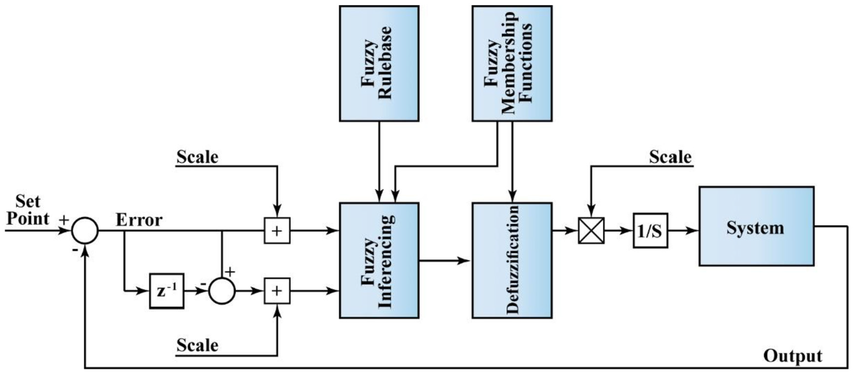
(C-2) In 1990 Chi-Hua was almost the first scientist to design a jet engine controller with respect to the fuzzy logic theory and he published his investigation as the “Application of a Fuzzy Controller in the Fuel System of a Turbojet Engine.” In this paper, the fuzzy control was used as the control algorithm. Two design methods were introduced. The first was the membership degree method based on fuzzy sets theory. The second was the phase-plane method based on engineering control. A microcomputer was used to implement the function of the fuzzy controller, based on the phase-plane method. At long last, the dynamic semi-physical simulation test for the fuel control system of a turbojet engine in small perturbation was carried out. 127
Generally, the error and first derivative of error were taken as the input signals for the fuzzy controller. Each input was divided into some input fuzzy subsets. This division changed the input signal from being accurate to being fuzzy. The output of the fuzzy controller was a definite accuracy value. The output of the controller was obtained from the calculation and strategic decision of fuzzy control.
From the results of simulation tests, it was indicated that the system using fuzzy control has good performance, such as no overshoot, short settling time, etc. Hence, a new research field (turbine engines) had been opened up for the application of fuzzy control.
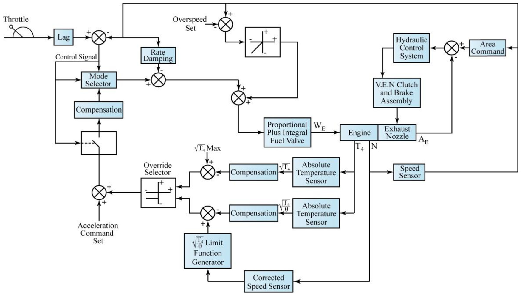
(C-3) In 1990 Rosenblad carried out an investigation on the “Evaluation of Control Techniques for Aircraft Propulsion Systems.” This study benefited from various facilities like multivariable compensator generation, real-time dynamic system simulation, and hardware-in-the-loop closure which are brought by digital computer simulation for his purposes. 128 The schematic of the used framework is shown in Figure 12.
In this investigation, all subsystems were integrated. For taking advantage of the sensitivities between systems, this system integration necessitated common control.
This was one of the first attempts carried out to implement all subsystems as a model with a multivariable controller model in a computer to verify its application.
The approach to their evaluation presented in this paper was a cost-effective means for determining their advantages and for supporting their implementation. This facility enables the design engineer with the possibility of designing and evaluating a control system with only the knowledge of the system that must be controlled.
Block diagram of a simulation test adapted from. 127
Test facility of hardware in the loop adapted from. 128
(C-4) In 1995 Jones et al. published a “real-time expert system for flight control.” Landing procedure control for a specific business jet under a variety of situations was the goal of this expert system. 129
The main components of this system were a supervisor, main control modules, and low-level controllers. The duty of the supervisor was to recognize the flight and aircraft condition and to determine what should be done as a system decision. The supervisor did not act as a direct effect on flight control and handled by the control modules.
The powerful flight control system can be achieved by the combination of neural networks with expert system technology. One of these system capabilities was the ability to control different flight conditions, such as landing with one engine inoperative.
(C-5) In 1996 Hlirefors designed a multivariable controller for a jet engine and published his achievement. Designed control laws were based on H
The functions of the controller were divided into modules. The duty of these modules is steady-state reference values calculation, reference trajectories generation, the closed-loop controller, the control signals restriction and other modules stand for the actuator control loops and failure detection for the engine sensors. It should be mentioned that all clarified modules were implemented in software in a FADEC system.
The proposed multivariable control concept demonstrated the potential of using more advanced control methods, as both stability and response were improved.
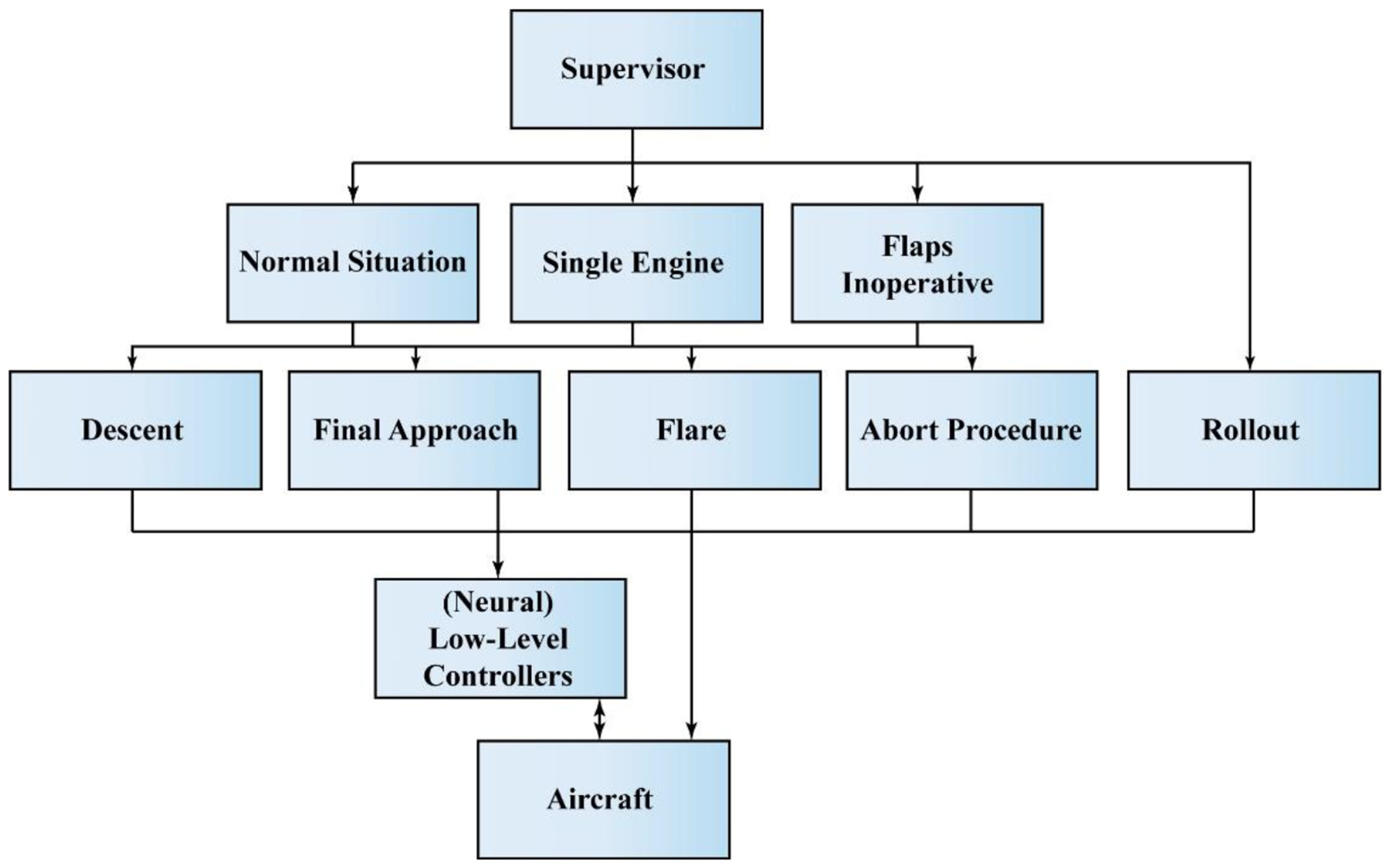
General layout of the controller structure adapted from. 129
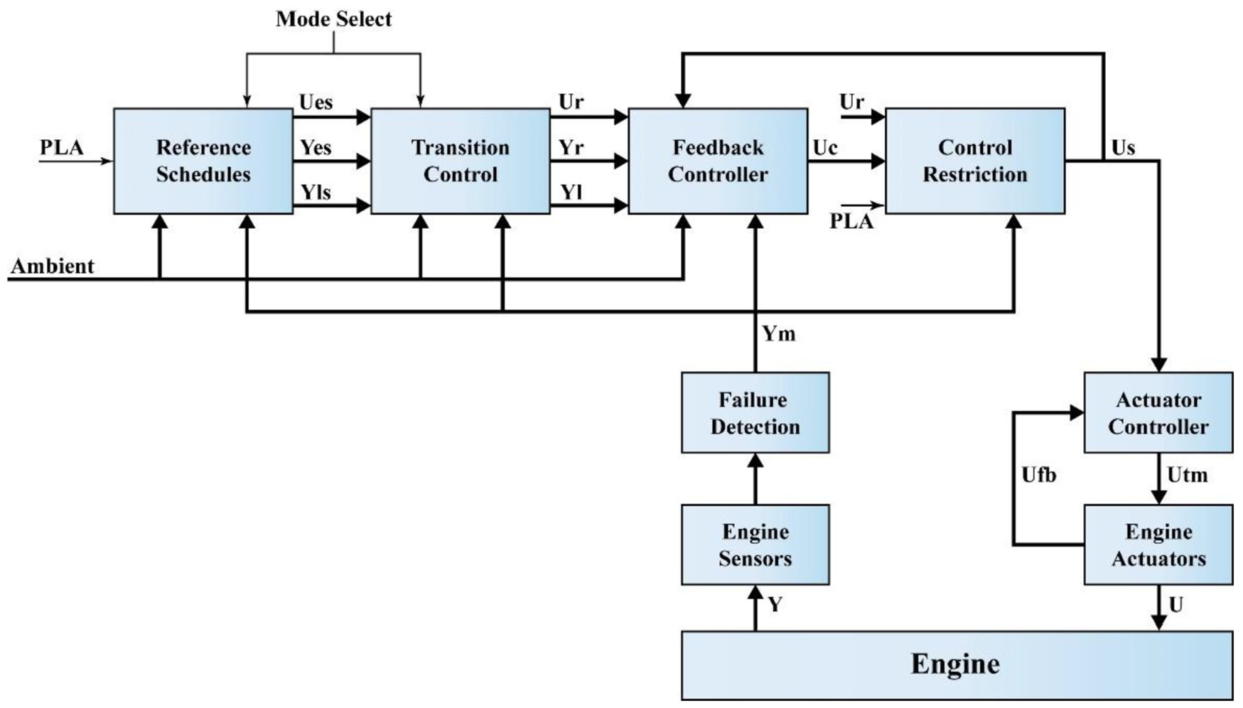
Structure of the main controller adapted from. 130
(C-6) In 1999 H. Austin Spang et al. published a paper investigating the basics of controlling an engine while satisfying numerous constraints. It was shown that the engine necessity operation as close as possible to its limits led to its control complexity. Paper results showed that a series of SISO controllers would be plausible for commercial engines and multivariable controllers are suitable enough for military engines. 131
(C-7) In 2000 Zilouchian et al. again, used fuzzy logic for jet engine fuel flow control; in this paper, authors took fuel delivery control in a jet engine test bench as the consideration system. They considered two methods for fuzzy logic controllers designing, (a) first: tool development with rules and membership functions as inputs and consequences as outputs, (b) second: a method based on development and scaling of the bivariate curve. The authors proved that controllers which are designed based on these methodologies have considerable benefits than conventional controller which is currently being utilized for the combustion pressure on jet engines control. 132
Two fuzzy logic methods were explained in detail and their applications were introduced. The engine model as well as the controller were also clarified.
Controller sensitivity to feedback signal noise was the only first fuzzy controller problem. But this problem successfully solved by the second and therefore this was the preferred method.
(C-8) In 2002 Fantoni et al. introduced “a simple stabilizing algorithm for the planar vertical takeoff and landing (PVTOL) aircraft.” The controller was designed based on the presented algorithm did not have any discontinuities and singularities. 133
The PVTOL aircraft model and stabilizing control laws were declared mathematically and analyzed carefully. Finally, the controller was simulated successfully.
(C-9) In 2004 Gang et al. one of many studies dealing with multivariable controllers, introduced a method for the reduced-order H
As mentioned above, the authors offered two methods that were carefully investigated, and their application was proved by examples.
From 2004 until the present day, global requirements and many new physical limitations and environmental criteria have appeared and, because of these, controllers have changed, based more on electric and electronic concepts. More advanced controllers have been designed and manufactured during this time and are introduced below (D-1 to D-8).
(D-1) NASA (GRC) investigated improvements: 112
Model-Based Engine Controls and Diagnostics as Figures 16 and 17:
Having an accurate enough on-board model that presents engine condition correctly.
A set of “tuners” which have a good estimation of unmeasured engine performance and operability has been developed by The GRC.
Control and Diagnostics Technology Development by Engine Dynamic Models
Distributed Engine Control
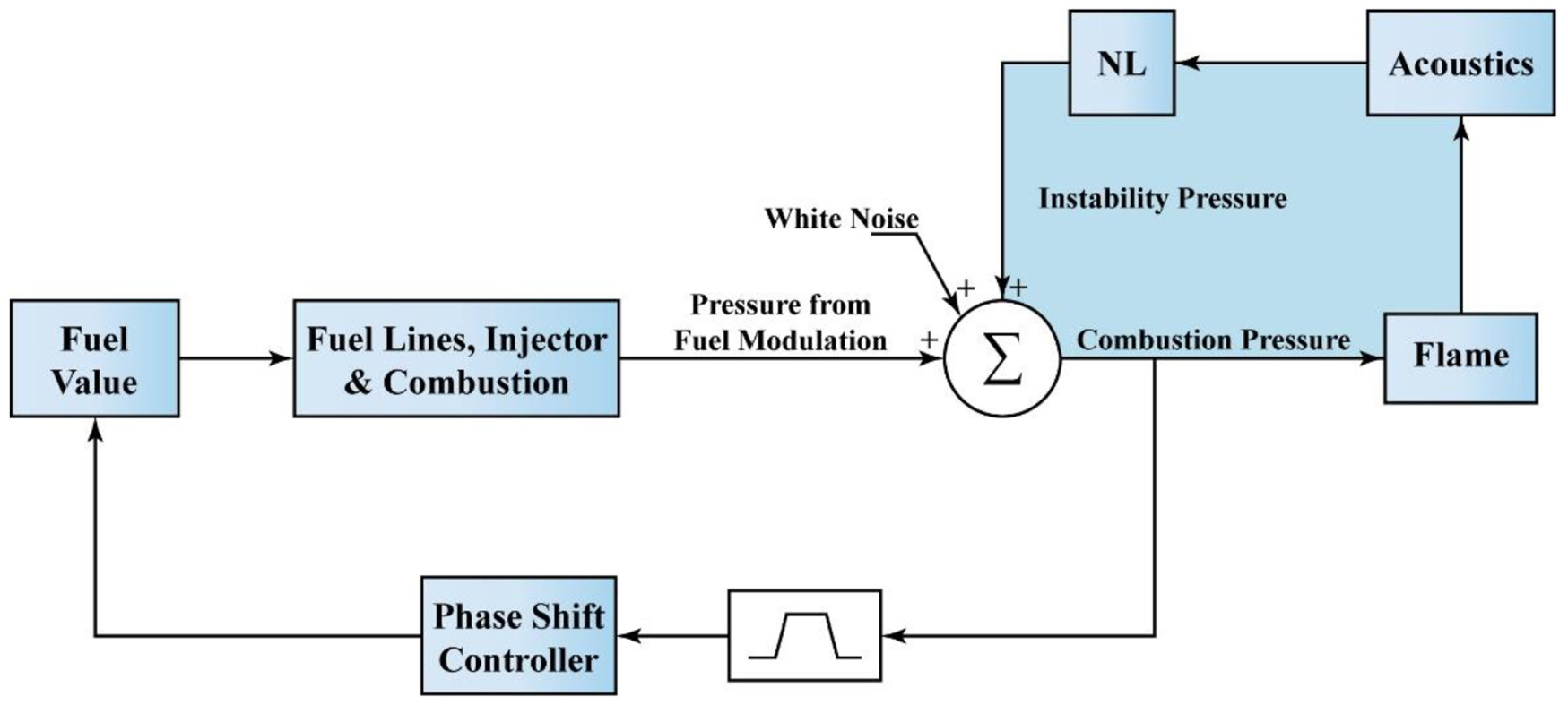
Active Combustion Control
The active suppression of combustion instability in a realistic aero-combustion environment possibility was declared by The GRC in 2005.
Low NOx Combustor Configuration which is demonstrated by Combustion Instability Suppression: this NASA (GRC) development could control the combustion instability growth with the adaptive sliding phasor averaged control.
High-Speed Propulsion System Dynamic Modeling and Control
Closed-loop control system configuration adapted from. 132
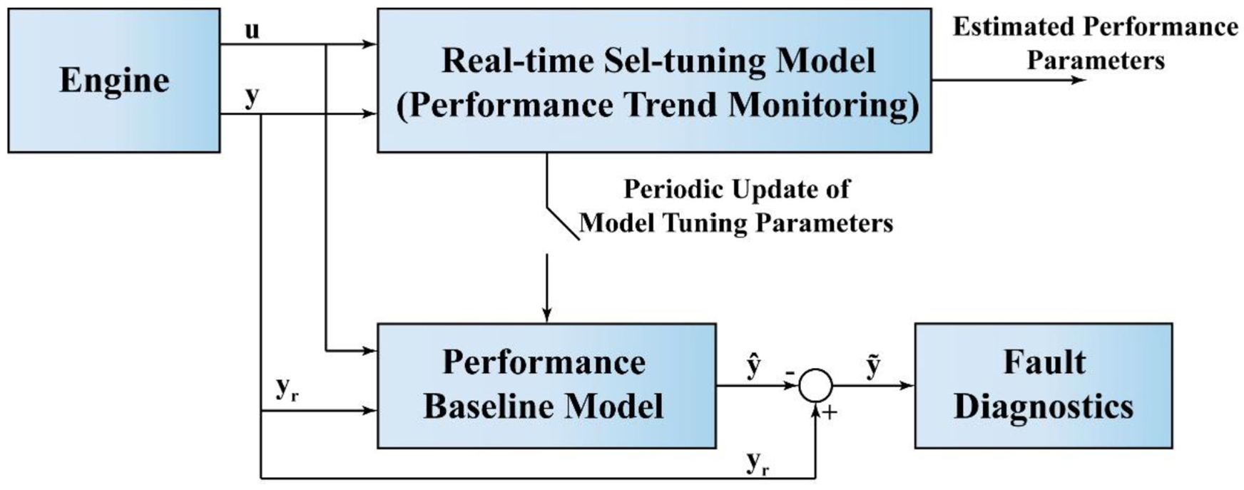
An integrated architecture for monitoring and fault diagnostics of aircraft engine performance adapted from. 112
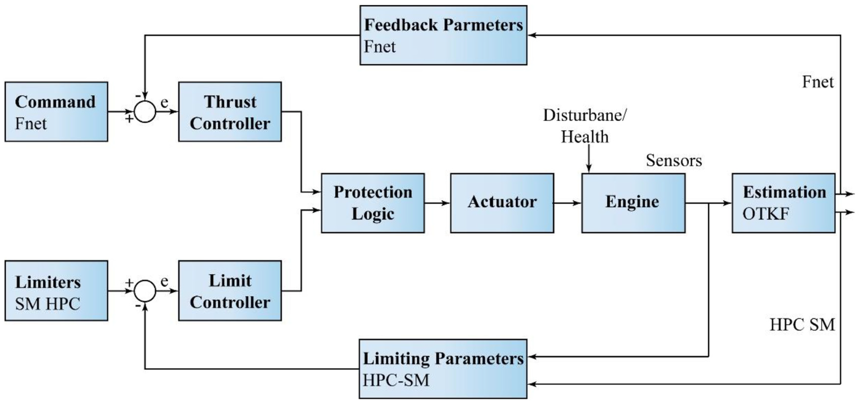
An architecture for model-based engine control to provide thrust and stall margin tight control adapted from. 112
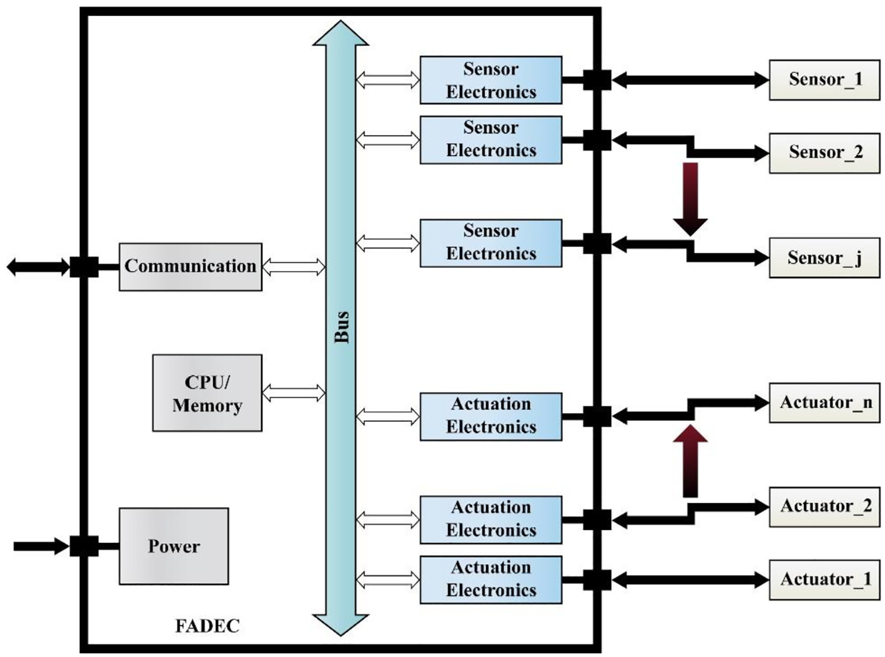
Centralized engine control adapted from. 112
Distributed engine control adapted from. 112
(D-2) In 2005 Miklosovic et al. declared a new method called unknown input observer (UIO) which was a dynamic decoupling method and proved that it could be used for controlling high-performance turbofan engines. 135
They declared mathematical equations for the dynamic decoupling method and also used the Modular Aero-Propulsion System Simulation (MAPSS) package to apply their clarified method.
Simulation preliminary results showed the new suggested method capability and its high-frequency gain characteristics.
(D-3) In 2007 Andoga et al. published “digital electronic control of a small turbojet engine, the MPM 20.” They evaluated and proposed a system for the small turbojet engine digital measurement. They proposed engine different models and designed situational control algorithms for each one, using artificial intelligence certain methods. 136
They outlined the situational control methodology and designed a FADEC control system for the MPM 20 from the point of view of both software and hardware.
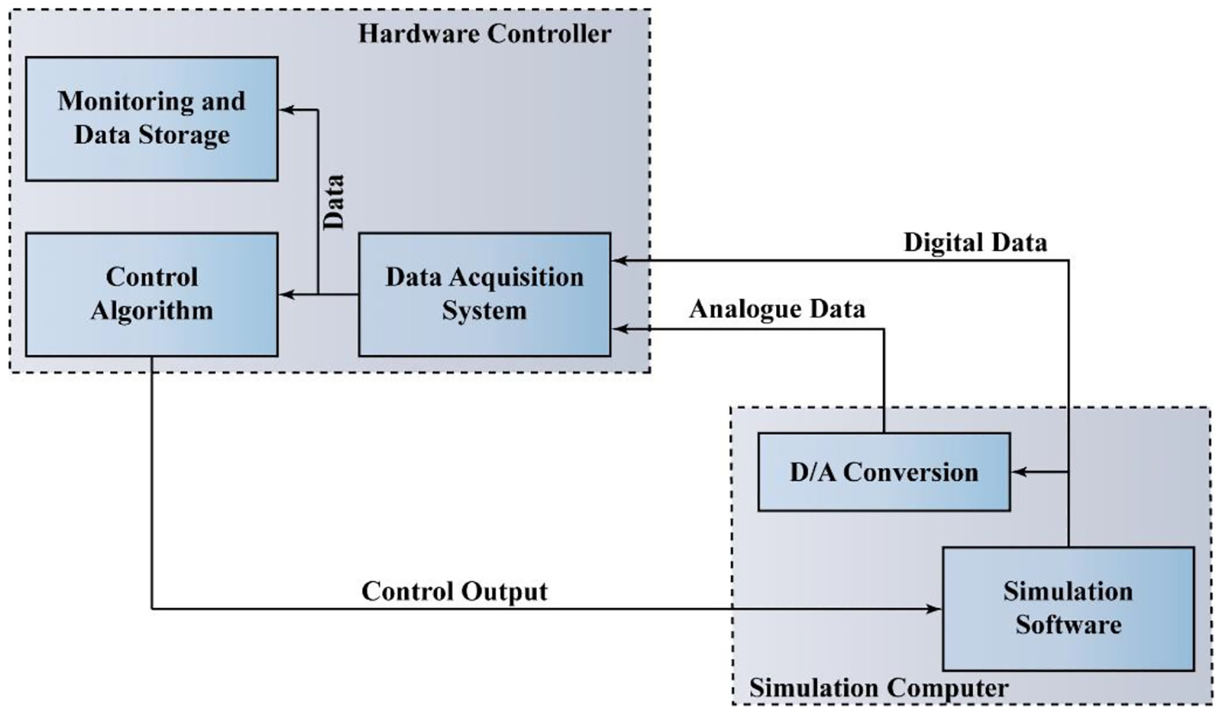
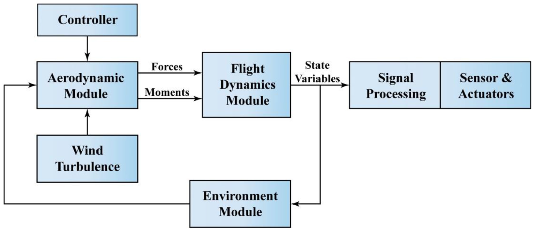
(D-4) During this period, many investigations were carried out on unmanned aerial vehicles’ (UAVs) flight systems. One of the best examples of this is by Lu et al. published in 2010. They simulated their designed controller in real-time based on Matlab/Simulink software 137 with the structure presented in Figure 21.
Based on the UAV mathematical model they built the UAV nonlinear model and established their model in the Matlab/Simulink environment. The xPC Target system was used for the whole HIL simulation system. By comparing the results with a flight test, they showed the modeling theories and method’s validation.
They outlined in detail the mathematical model of the UAV and defined a flight dynamic model in Matlab/Simulink.
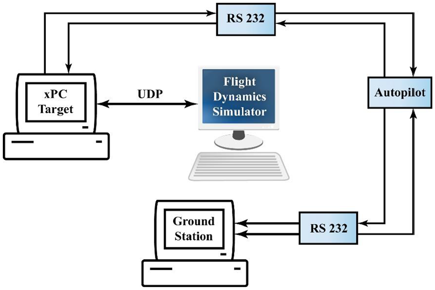
The hardware system components were simulation computer, target computer, autopilot, and the ground station as shown in Figure 22.
The result of the UAV hardware-in-the-loop (HIL) simulation test showed that the HIL system has many capabilities to precisely simulate this system, and provided a suitable system to enable the verification of flight performance. With this paper’s results, it was proved that HIL simulation is correct for determining control and navigation law, and besides that, it is suitable for reducing cost and flight risk.
Advanced control methods for active combustion control adapted from. 112
The UAV simulation model Structure adapted from. 137
The HIL simulation system Structure adapted from. 137
(D-5) In 2006, Simon et al. published “Kalman Filter Constraint Switching for Turbofan Engine Health Estimation.” 138
This paper proposed a new method for using residuals for constraint switching. With the dynamic model used in simulation experiments, the authors discussed the problem of turbofan health parameter estimation and then showed the way of this problem expression for being compatible with their discussed constraints. The authors proved that the constrained Kalman filter could estimate health parameters better than the unconstrained filter.
The authors also presented further work suggestions to explore the relationship between moving horizon estimation and projection-based constrained estimation.
(D-6) In 2016 Seok et al. published a comprehensive research study titled: “Integrated/Coordinated Control of Aircraft Gas Turbine Engine and Electrical Power System” to respond to thrust commands while maintaining the efficiency of the system operation at a high level and satisfying the input and state constraints, a Model Predictive Controller was designed. The simulation results which are based on the nonlinear model were reported as the paper conclusion. 139
They proposed an engine linear model and its controller and widely discussed model predictive control (MPC) design procedure.
(D-7) In 2019 Jafari et al. published their research on future aircraft propulsion systems that are able to meet the ambitious targets and severe limitations imposed by governments and organizations. 140
This paper presented an advanced control design procedure for full authority digital engine control (FADEC) systems to minimize the emission levels in the next generation of turbofan engines in order to deal with Flightpath 2050 regulations. For this purpose, a reliable validated model for a turbofan engine was first developed using the adaptive network-based fuzzy inference system, nonlinear autoregressive network with exogenous inputs techniques, and the block-structure Hammerstein-wiener approach. The Min-Max control structure was selected; the objective function was then defined to minimize the emission level for the engine and the developed engineering optimization problem was dealt with by a genetic algorithm to find the optimized control structure for the engine.
Emission level calculation for CO, NOx, and SN in steady-state and transient operations in different flight phases was calculated to confirm how the optimized controller was effective in reducing pollutant emissions regarding the targeted limitations of the ACARE Flightpath 2050. The objective functions were formulated and three scenarios were proposed to design environmentally friendly optimized controllers. Three optimal control scenario results were compared to assess the performance of the engine. The authors, based on the results of this paper, suggested one idea for the future that involved changing the controller setting during different flight phases adaptively to get the best emission performance for the whole flight.
(D-8) In 2019 Nikolaidis et al. proposed research based on an “advanced constraints management strategy for real-time optimization of gas turbine engines’ transient performance.” 141
The authors proposed a practical control mode satisfaction approach to attain the engine optimal transient performance. They developed a constraint management strategy for generating variety of settings for controller for short-range fighters, as well as long-range intercontinental aircraft engines at different operating conditions by applying an MPC approach. After that regarding the different realistic considerations, they tuned and modified the designed controller.
The authors declared most important part of their contribution for the new GTEs generation as follow: a) practicality considerations: they claimed that the control strategy and all laws which were used to design controller are based on realistic assumptions; b) system dynamics considerations; c) implementation considerations: these were considered in two ways, (a) controller structure implementing facility, (b) real-time simulation and optimization capability;
In addition to these publications, there are other studies that could not be clearly accommodated within the above-mentioned four phases. Specifically, the border between the third and fourth phases is vague, and some research could be considered to belong to both. The most important studies with this characteristic are categorized below based on their control methods and how they were implemented:
Publications based on fuzzy control methods:
One of the most favored control methods is the fuzzy logic control concept.
In 1998 Zhongxiang et al. described a two-variable fuzzy control strategy, synthesized a new fuzzy-PI controller, and studied the decoupling characteristic and responsibility of a controller in an aero-engine using dynamic simulation. 45
In 2010 Amirante et al. for conventional PID controller replacement proposed a fuzzy technique for direct thrust control in small turbojet engines. 16
In 2011 Bazazzadeh et al. introduced a fuzzy logic controller strategy for a specific jet engine. They presented a plausible mathematical model for the jet engine firstly. Then, they applied different fuel flow functions via this model. 105
In 2014 Üşenmez et al. proposed a mathematical modelling approach for small-scale turbojet engines based on system identification tests. They designed a Classical PI controller and an FLC to enhance transient response and steady-state performance improvement. 14
In 2018 Jafari et al. published a paper examining the potential of using fuzzy T and S norms in Min-Max selection strategy to improve the controller and dynamic behavior performance of the gas turbine engine. 111
Publications based on robust analysis controllers:
Some articles used robust stability analysis tools and demonstrated that these analysis techniques can provide a simpler analytical insight into uncertain systems.
In 1997 Ariffin et al. presented a study on part of the control system for the Rolls Royce Pegasus aero-engine under various operating conditions, and it was shown its capability to improve engine performance and robust stability. 47
In 2000 Frederick et al. used a robust multivariable control approach, which in those years had been developed at the NASA Glenn Research Center, to be applied to advanced linear and piecewise linear models of turbofan engine. 31
In 2009 Yu et al. proposed “multi-objective robust regulating and protecting control for aero engines.” 51
Publications based on tuning and gain scheduling:
Some other important articles focused on the parameters of tuning and gain scheduling.
In 1991 Koivo et al. published a survey on the gain tuning methods of PID controllers and declared the different approaches for unknown plants. 97
In 2011 Montazeri et al. presented a genetic-fuzzy to satisfy all engine control modes simultaneously without switching nature. 61
In 2012 and 2014, Xiaofeng et al. published two comprehensive studies that presented an approximate nonlinear surge margin model of aircraft engine compression system based on equilibrium manifold expansion.142,143 This idea could be used effectively for tuning of model-based controllers to control the unmeasurable parameters of GTEs directly (e.g. surge margin control).
In 2013 Pakmehr et al. developed and described a gain scheduling control approach for a variable pitch propeller gas turbine engine.71,72
Publications based on switching control strategy:
Another category includes articles that present a switching control strategy.
In 2014 Qi et al. used a state-based switching control strategy application concerning the thrust regulation and safety protection for aero engines. 43
In 2014 Xiaofeng et al. based on switching characteristics designed multi-objective controllers for aircraft engine and used these characteristics for solving control problems of regulating and protecting 144 another multi-objective control system based on switching and its applications introduced by Xiaofeng et al. in145,146 that focused on smooth switching behavior in GTEs control systems.
In 2017 Chen et al. proposed “a nonlinear switching control strategy to solve the regulation control problem with safety constraints for aero engines based on the equilibrium manifold expansion model.” 22
In 2018 Shi et al. presented an article that was focused on rotational speed regulation control for a two-spool turbofan engine. After assessment aero engine operation characteristics, based on multiple operation modes they gave multiple switched equilibrium manifold expansion models. Then they defined switching laws based on aero-engine operation characteristics and performed a supervisor for checking among aero-engine modes. Finally, to achieve the aero-engine control system robustness, an optimal control strategy was employed. 33
Publications based on controller optimization parameters:
There are many articles in the field of optimizing the performance of aero engines, controller gains, and other characteristics in this category.
In 1991 Smith et al. proposed a performance seeking control (PSC) algorithms based on an adaptive, integrated flight/propulsion control to enhance aircraft performance during steady-state engine operation. 96
In 2007 Tavakoli et al. presented a simple PI controller to obtain good responses to setpoint and load disturbance signals, good robustness, and small variations of the control response and finally used multi-objective genetic algorithms to deal with engineering optimization problems. 99
In 2011 Montazeri et al. proposed the “application of an evolutionary algorithm for optimization of the Min-Max fuel controller parameters in gas turbine engines.” 106
In 2012, again, Montazeri et al. declared the “application of the particle swarm optimization algorithm for optimization of the gas turbine engine fuel control system.” 107
In 2013 Jafari et al. published the” invasive weed optimization (IWO) for gain tuning of turbojet engine fuel controller.” 108
In 2014, again, Jafari et al. published a paper that presents a multi-objective invasive weed optimization algorithm based on Multi-Criteria Decision Making (MCDM) methods to design an optimized controller for aero engines. 109
In 2016, again, Tavakoli et al. studied the possibility of tailoring a simple and effective PI controller to be tuned to satisfy both performance requirements and robustness issues. 101
In 2018 Songet et al. published the “optimization for the starting process of turbofan engines in a high-altitude environment.” 24
Publications based on implementation and fault-tolerant:
One of the most important aspects for each controller is how it works in the real world. Many scientists test their controllers in the real world and have published their results as a hardware implementation in journals.
Orme et al. proposed a performance seeking control (PSC) as a model-based, adaptive control algorithm, which was flight-tested on an F-15 aircraft. The performance optimization of the integrated propulsion system when it is on steady-state mode was the aim of this algorithm. 98
In 1999 Hollmeier et al. outlined a two-dimensional analysis for a combined turbofan-ramjet engine by utilizing an integrated real-time simulation and flight simulator based on performance analysis. 32
In 2011 Montazeri et al. developed and manufactured a multi-rate Hardware-in-the-Loop (HIL) simulation platform for turbojet engine fuel control system testing. 62
In 2015 Hrabovský et al. presented a methodology for the application of “anytime” strategies into a digital real-time control for a small turbojet engine iSTC-21v. 13
In 2016 Beneda published a paper with the goal of describing the “development of a modular FADEC system for a small-scale turbojet engine” covering both research and practical aspects of FADEC design. 12
In 2016, Ding et al. investigated “Online Fault-Tolerant Onboard Aeroengine Model Tuning Structure” based on Online onboard aero-engine models(OBEMs) and proposed a fault-tolerant OBEM tuning structure to attain the online tuning function when the system faced with both health degradation and sensor fault. 147 In another investigation in 2017 again Ding et al. proposed this tuning system with a hybrid Kalman filter. 148
In 2018 Li et al. proposed a controller that was focused on designing a network for a mixed flow twin-spool turbofan aero engine with degradation effects and deterioration. 37
Publications based on engine model or controller distribution:
There are many investigations related to the distribution of aero-engine models and their controllers or any other electronic devices.
In 2009 Pakmehr et al. developed theoretical concepts for distributed control of GTEs.73,74
In 2011 Pakmehr et al. gave a summary of integrated high-temperature electronics and distributed engine control. 75
Performance models of gas turbines developed using the bond graph approach89–93 are used in the design and optimization of control systems. For instance, Jafari et al.92,93 studied electric start systems of gas turbines and jetquads with the aid of the bond graph method. Also, regarding hybrid propulsion systems as a combination of electric systems and gas turbines, one can benefit from bond graph models of gas turbines.
Publications related to electric aircraft:
Very recent activities in aero engines have focused on More Electric Aircraft (MEA) and hybrid electric aircraft, our final category in this survey.
In 2010 Zhang et al. mentioned that the local DC power distribution system of MEA was one of the main players in electric power transmission and declared that because of the unidirectional mechanical source (turbine engine), the system is not totally reversible. 100
In 2015 Gao et al. published “an improved voltage compensation approach in a droop-control DC power system for the more electric aircraft.” 104
In 2018 Braitor et al. outlined “control of DC power distribution system of a hybrid electric aircraft with inherent overcurrent protection.” 102
Other important publications (based on citation):
Some of the most important investigations that can’t be placed in the above categories are presented here in the order of their publication date.
In 2002 Balas outlined the “linear, parameter-varying control and its application to a turbofan engine.” 30
In 2010 Rahman et al. explained how the blended-wing-body aircraft controls could be saturated and how the dynamic performance becomes sluggish at low airspeeds with nominal static margins. 26
In 2010 Pakmehr et al. developed theoretical concepts for decentralized adaptive control with partial communication. They used a twin-spool gas turbine engine as the case study. 78
In 2013 Pakmehr et al. also outlined “verifiable control system development for gas turbine engines” with the specific software. 76
In 2014 Xiao developed “aero engine multivariable nonlinear tracking control based on uncertainty and a disturbance estimator.” 44
In 2018 Yazar et al. proposed a modified rotational speed control strategy for small-scale turbojet aero engines based on a nonlinear mathematical model. 15
In 2019 Bai et al. presented the “nonlinear single controller of DGEN380 aero-engine design.” 20
In 2019 Yu proposed “a novel control scheme for an aircraft engine based on a sliding mode control with acceleration/deceleration limiter.” 21
In 2019 Sanusi et al. utilized adaptive dynamic programming to introduce a condition-based control framework for GTEs. 103
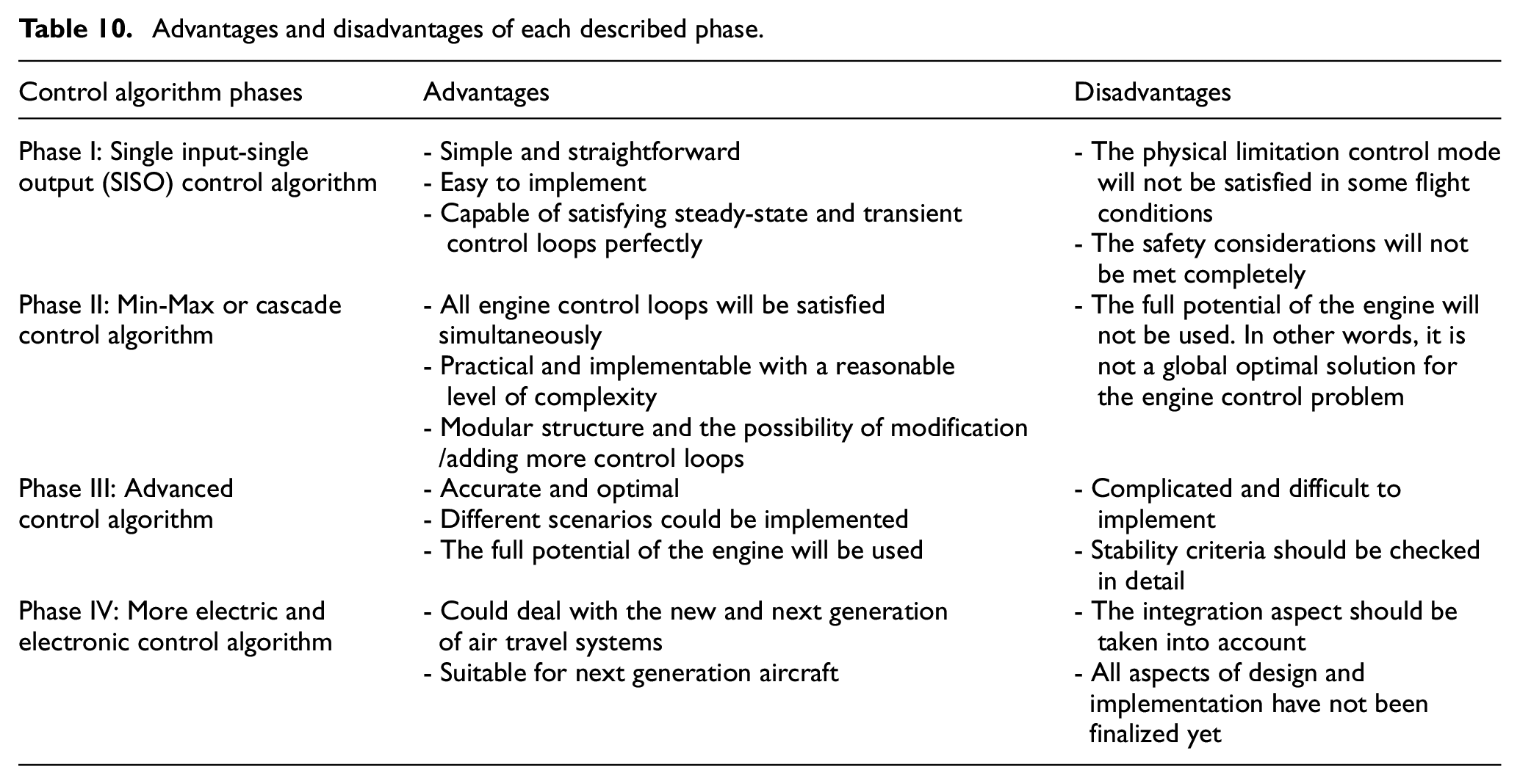
Table 10 present the pros and cons of each phase described above.
Advantages and disadvantages of each described phase.
Finally, it is worth mentioning that in ramjet and scramjet cases, as the operating cycle and components are different from a jet engine, different control requirements and control strategies should be considered to satisfy all control modes simultaneously. The main control requirements for these cases are comprehensively discussed in 149 where the basic fuel metering requirements for ramjets were defined in an Advanced Integral Rocket-Ramjet Propulsion System (AIRRPS). This study presented the need for a separate light-off schedule and manifold quick-fill scheme as well as the necessity of the inlet margin limiting including vehicle velocity and air-to-fuel ratio limiting. Simple and practical control strategies to satisfy the identified control requirements are presented and discussed in 150 where different control laws for starting, acceleration, and cruising stages were developed mainly based on PID algorithms. The experimental results presented in this study confirmed the effectiveness of the PID control strategy in dealing with ramjets control requirements.
Moreover, the advanced aspects of ramjet and scramjet controls are well-studied recently as follow:
In 2014, Cao et al. proposed an idea for thrust regulation switching control and inlet unstart protection for scramjet engine based on Min strategy in order to satisfy safety restrictions during the ascent trajectory of a scramjet engine and attain optimal thrust performance. 151 They also extended their proposal based on the strategy of integral initial values resetting in 2015. 152
In 2018, Zheng et al. published “Performance uncertainty propagation analysis for control-oriented model of a turbine-based combined cycle engine” and investigated on the source of these uncertainties, performed model simulation with uncertainties inputs and finally gave a full analysis for their control model to confirm the effectiveness of the proposed approach in real-world control scenarios. 153
In 2018, Ma et al. presented a control-oriented modeling approach used in a real-time simulation platform for a dual-mode scramjet combustor. 154 They also extended their study to unsteady one-dimensional feature for a hydrocarbon regeneratively-cooled scramjet engine 155 and multi-objective coordinated control of a regeneratively-cooled scramjet engine with two-stage kerosene injection. 156
In 2019, Zheng et al. published a study titled “Modeling and analysis for integrated airframe/propulsion control of vehicles during mode transition of over-under Turbine-Based-Combined-Cycle engines.” They described mode transition control as a critical issue of the Turbine-Based-Combined Cycle (TBCC) engine and proposed a nonlinear longitudinal TBCC-powered dynamic vehicle model and designed a control-oriented model with six control inputs which were obtained by approximately expressing aerodynamic coefficients through curve-fitting methods. 157
Conclusion
Gas turbine aero-engines control strategies and structures proposed over the past eight decades were critically reviewed and analyzed. Initially, the benefits and physical principles of gas turbines and their control systems were expounded together with the pros and cons of different types of aero-engines. Based on the detailed scientometric analysis, several designs and embodiments dating back to 1948 were identified and examined in detail. Four gas turbine control design phases were defined to put historical concepts into context. The single input single output control strategies as the most simple and straightforward approach taken into account by Rolls-Royce and GE in the first phase of the development of gas turbine controllers. Considering the drawbacks of SISO controllers in dealing with the physical limitation control modes, the Min-Max controllers are developed and implemented on aero-engines as the most successful industrial control algorithm to satisfy all engine control modes simultaneously. However, this control structure does not use the maximum capability of the engine, especially during large acceleration/deceleration. Therefore, modern control approaches including fuzzy logic controller, model predictive control, and multi-variable control algorithms are being developed for new and next generation of aircraft engines to optimize the performance of the engines for dealing with the environmental considerations and limitations set by governments and organizations. Finally, by the development of more-electric propulsion systems in recent years, more control loops and considerations should be considered. In other words, the main structures of the control systems should be modified to satisfy the advanced control modes in more-electric propulsion systems.
Footnotes
Declaration of conflicting interests
The author(s) declared no potential conflicts of interest with respect to the research, authorship, and/or publication of this article.
Funding
The author(s) received no financial support for the research, authorship, and/or publication of this article.