
Abstract
The force-to-rebalanced control mode is the main operating mechanism of the HRG, and the standing wave azimuth of the resonator points to the 0° direction. But the bias of the HRG is very sensitive to the change of external physical field environment and it is urgent to improve the bias stability. The relationship between the bias of the HRG and the standing wave azimuth is periodic. When the standing wave azimuth and the damping axis are aligned, the bias error of the HRG will be greatly reduced, and the bias stability of the HRG affected by the temperature can also be improved by changing the azimuth of standing wave. In this paper, the control algorithm and the hardware circuit of the HRG are designed to control the HRG at any standing wave azimuths. The control of the HRG in different standing wave azimuths is realized, and the system temperature experiment is carried out. The experimental results show that the bias of the HRG are significantly different at different standing wave azimuths, and the bias stability of the HRG affected by the temperature can be improved 3 times by changing the standing wave azimuth.
Keywords
Introduction
The hemispherical resonator gyro (HRG) is a kind of vibrating gyro which can detect the rotation of gyro carrier by the precession effect of a vibration standing wave on the hemispherical resonator. In recent years, the researchers pay more attention to the HRG and the HRG is widely used in the field of inertia technology because of high precision, long life, simple structure and good reliability.1–6
The hemispherical resonator is the core part of the HRG, which is usually made of fused silica glass.7,8 Its vibration frequency is usually in the range of 4000 Hz–8000 Hz, the Q factor is higher than 10 million, and the frequency splitting is better than 0.0005 Hz. 4 The measurement of the HRG can reach an extremely high level of accuracy because the Q factor is very high and the frequency splitting is very low. However, the HRG is disturbed by the external physical fields such as temperature,9,10 vibration,11–13 and acceleration,14,15 which affects the measurement accuracy and limits the practical application of the HRG. The research of the HRG is to ensure the stability of the measurement accuracy when the external physical field changes. The bias stability is one of the main indicators to measure the accuracy of the HRG, the error of measurement caused by the external physical field is uncertain because the practical engineering application environment of the HRG is random, which leads to the obvious change between the bias of the HRG and the error of the measurement. At present, there are many methods to improve the bias stability of the HRG. The one is to suppress the change of the external physical field and ensure the external environment stability of the HRG by the additional hardware, which achieved temperature control, vibration reduction and electromagnetic shielding. 16 But cost of the HRG will be increased and the performance of gyro will be affected by the accuracy of the temperature control, the vibration isolation and the shielding efficiency. The other method is the self-calibration17–19 which based on the bias characteristics of HRG, in this method, the bias value can be obtained by modal inversion or virtual precession, and the output results are compensated and updated. This method has very high accuracy, but needs extremely high requirements on the control algorithm and control accuracy.
Focus on the problem that the bias of the HRG is easily affected by the external physical environment, the paper propose a method of reducing the bias to improve the stability of the HRG bias. The bias of the HRG with under different standing wave orientations will be theoretically calculated, the control algorithm and hardware are designed to realize the force-to-rebalanced of the HRG in any azimuth, and the bias stability of the temperature in different standing wave azimuths is studied experimentally.
The bias and the bias stability of the HRGat different standing wave azimuths
The dynamic model of the HRG
From,20–21 the dynamic model of the HRG with the frequency splitting and uneven damping is as follows:
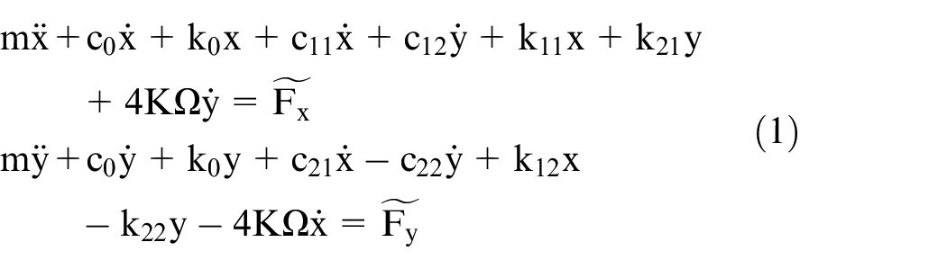
where
The spring-damping two-dimensional equivalent model of the hemispherical resonator.
The bias of the HRG
At different standing wave azimuths
where
The bias of the HRG at different standing wave azimuths.
The bias stability affected by the temperature
It is assumed that the temperature field is uniform in the resonator, i.e.

the damping, nonuniformity damping, azimuth and frequency of the HRG are all affected by the temperature, it is:

The bias of the HRG is a complex function of the temperature. The main sources of resonator damping include air, material, film loss and mass unbalance. It is considered that the influence of the temperature on the damping azimuth angle can be ignored for the uniform temperature field. At different temperatures, the frequency and damping of resonator are as follows: 9
where

Because the temperature field is uniform, it can be considered that the bias stability of
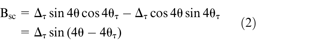
The bias stability of the HRG is affected by the bias and the nonuniformity damping. When the nonuniformity of damping is constant, the bias is modulated by the standing wave azimuth. When
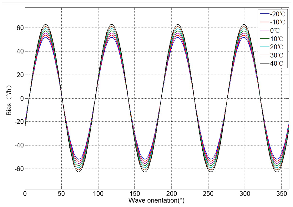
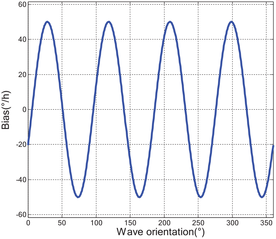
The bias of the HRG affected by the temperature in the different standing wave azimuths.
The simulation results show that the standing wave azimuth can be modified by changing the target amplitude of the two-mode. When the standing wave azimuth is the same as that of the damping, that is, when
The control method of different standing wave azimuths
The mode of two axis control force
In the force-to-rebalance mode, the amplitude closed-loop control of the HRG can be carried out independently by the x-mode and y-mode. At this time, the external input angular velocity can be obtained by monitoring the control force. The amplitudes of x-mode and y-mode are
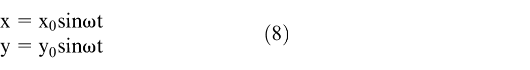
In Equation (8),
When Equation (8) is substituted into Equation (1), it is
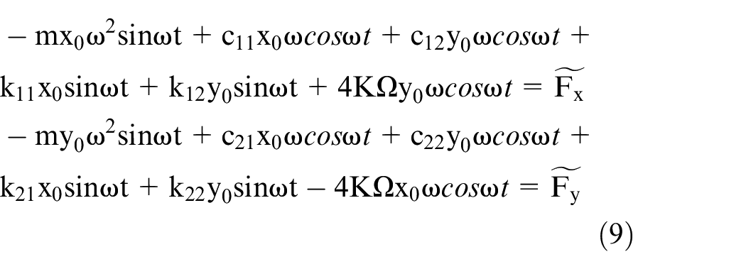
The control forces in Equation (9) are classified according to
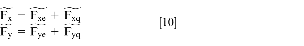
it can be obtained from Equation (9):
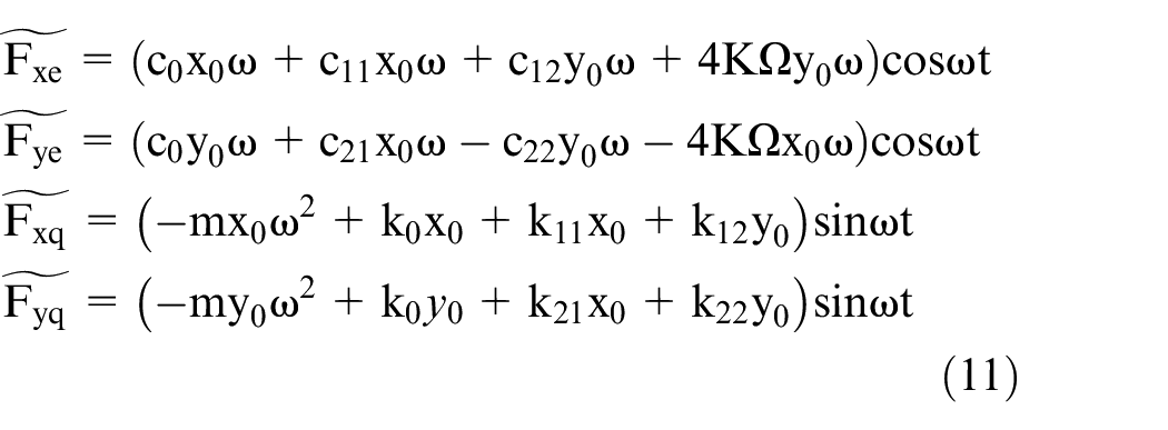
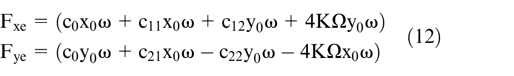
It can be seen form Equation (11) that the control force of the two resonant axes is consists of two parts: the amplitude control signal of the HRG which related the angular velocity and the orthogonal control signal of the respective resonant axes. After demodulation, the amplitude of the amplitude control signal is:
According to Equation (5), the control force is applied to the resonator to control the standing wave in
The HRG will introduce a larger zero bias because

where
The simulation of control
The basic parameters of the HRG are set as Table 1.
The parameters of simulation.
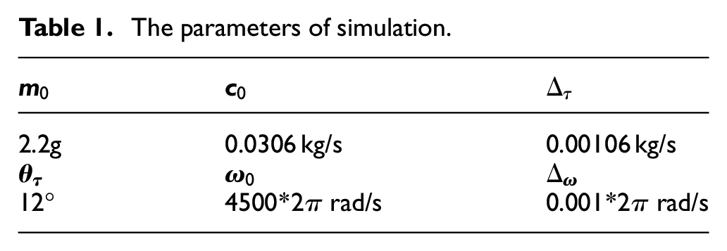
Then, the closed-loop control forces of the x-axis and y-axis are shown in Figure 4 respectively. When Fx = 0.93 V, Fy = 0.033 V, the amplitude on x-mode is 10 um, the amplitude on y-mode is 0 um, and the standing wave azimuth is at 0 °. When Fx = 0.88 V, Fy = 0.33 V, the amplitude on x-mode is 9.4 um, and the amplitude on y-mode is 3.4 um, and the standing wave azimuth is at 10 °. When Fx = 0.68 V, Fy = 0.64 V, the amplitude on x-mode is 7.7 um, and the amplitude on y-mode is 7.7 um, and the standing wave azimuth is at 22.5°. The simulation results showed that the hemispherical resonator can be controlled at any standing wave azimuths.
The force-to-rebalance control at different standing wave azimuths.
The control scheme and the experimental device of the HRG
The method of control
According to Equation (11), the angular velocity output of the HRG can be obtained by calculating of
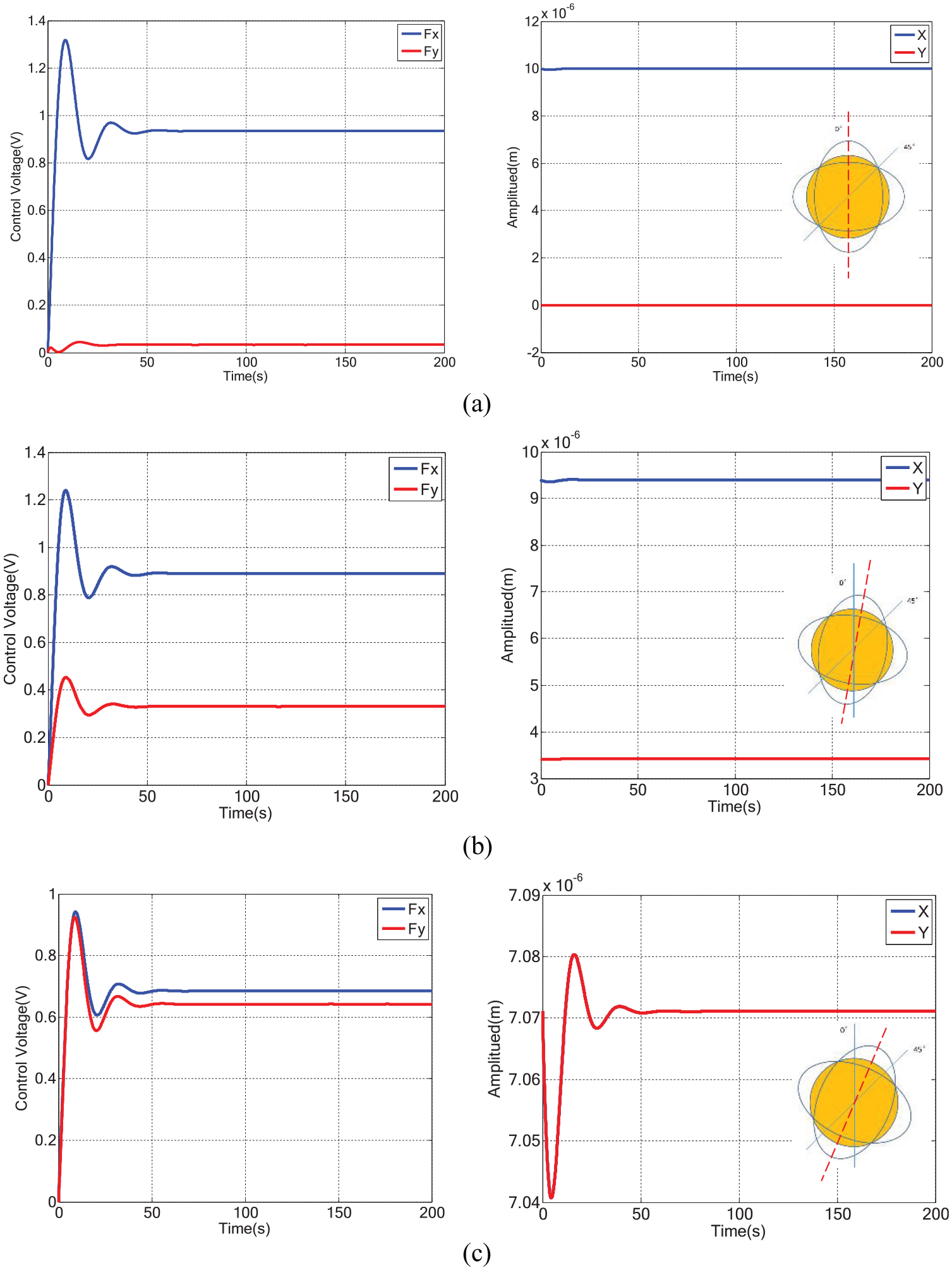
The control block diagram of the HRG.
The first is the loop of dual frequency tracking, it is composed of two phase-locked loops (PLLs), which are used to track the resonant frequencies of the two resonance modes x and y of the HRG. 28
The second is the loop of x-control loop (Drive X). By multiplying and demodulating the signal output of the x-mode of the HRG, the x-mode amplitude cx is obtained, and compared with the target value x0 to form an error signal. And PI controller is used to adjust the driving voltage of the loop, which is applied to the driving voltage corresponding to the x-mode, so the amplitude of the x-detection loop can reach the control target value.
The third is the loop of y-control loop (Drive Y). By multiplying and demodulating the y-mode signal output of the HRG, amplitude cy of y-mode is obtained, and compared with the target value y0 to form an error signal. And PI controller is used to adjust and apply the driving electrode corresponding to y-mode, so that the amplitude of the y-detection loop reaches the control target value.
The last is the loop of quadrature control (Drive Q).By multiplying and demodulating x-mode and y-mode signals of the HRG, the error signal of the quadrature cx·sy-cy·sx is obtained29,30. And PI controller is used to adjust and apply the driving voltage, so the phase of x-loop and y-loop can reach the control target value and the detection signal phase of the two loops is the same.
The experimental device
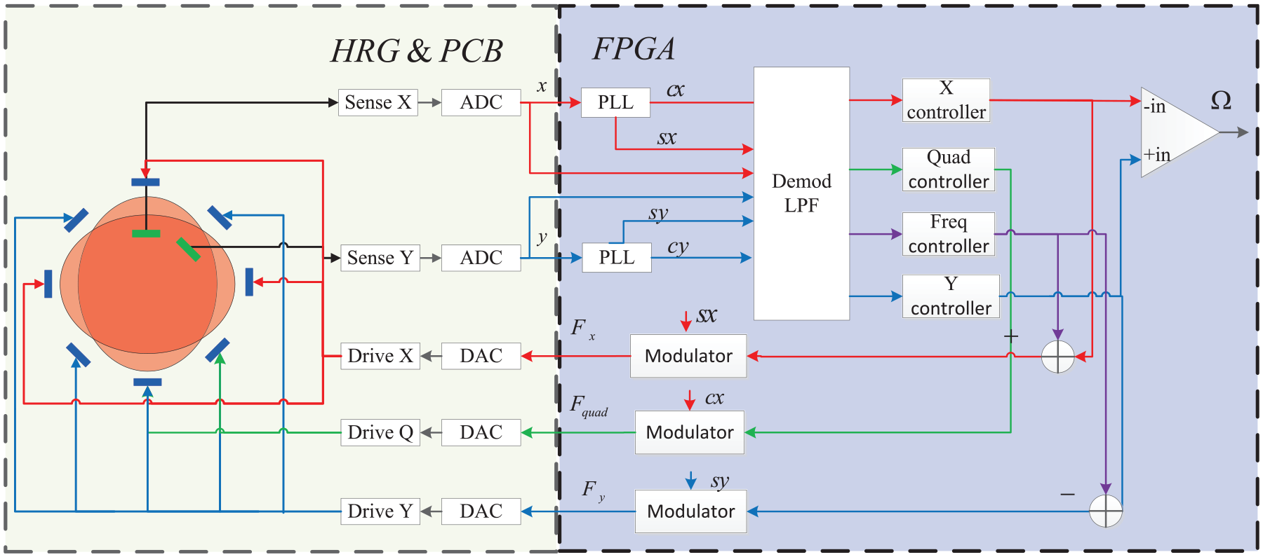
The experimental device of hardware and temperature control are shown in Figure 6. The experimental hardware includes the HRG, the buffer circuit, FPGA and the auxiliary peripheral circuits. The vibration signal generated in HRG is amplified by the buffer circuit, and then was input into FPGA for demodulation and combination operation, and last generates the signal required by the control circuit. The auxiliary circuit include power supply, communication chips, protection and isolation devices, etc. The signals of the circuit board and the HRG are introduced to the computer by the shield linearity, and the frequency, control voltage and control error of the HRG are collected. The temperature control is used to control the environmental temperature around the HRG, the temperature control range is set to 20°C∼60°C.
The experimental device of hardware and temperature control box.
The experiment of the bias stability
The control experiment of different standing wave azimuths of the HRG
Based on the control method and experimental device in the Section 4, the standing wave is controlled in different orientations of the experiment at temperature of 20°. When the standing wave azimuths are at 12.5°, 22.5°, and 32.5°, the results are shown in Figure 7. When the standing wave azimuth is controlled at 12.5°, the control forces in the x-mode and y-mode are 0.86V and 0.48V, respectively. When the standing wave azimuth is at 22.5°, the control forces in the x-mode and y-mode are 0.75V and 0.65V respectively. When the standing wave azimuth is at 32.5°, the control forces in the x and y modes are 0.48V and 0.83V respectively. The amplitudes of the x-mode and the y-mode are both stable over time, which indicates that the azimuth control of standing wave at any angle can be achieved.
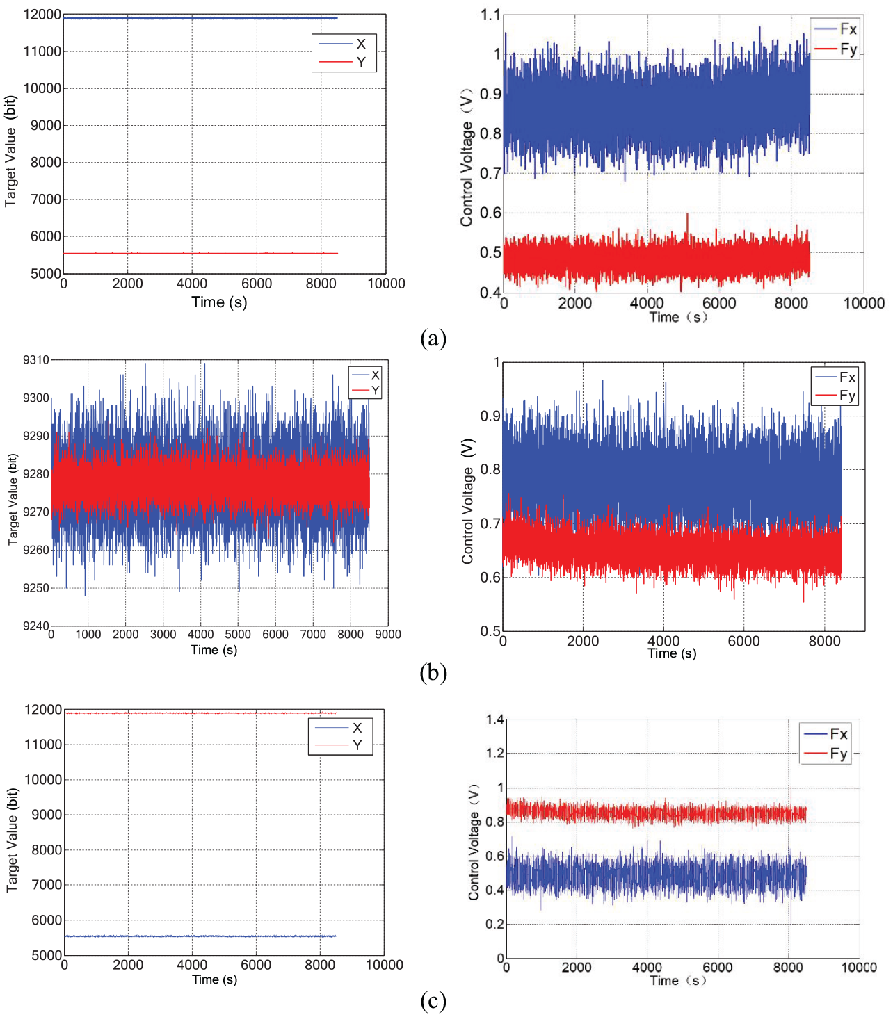
The experiment of force-to-balanced in different standing wave azimuths at temperature of 20°C. (
The bias stability of the HRG in the temperature field
The resonant frequency of the HRG can reflect the ambient temperature of the resonator 9 . Because the hemispherical resonator works in a vacuum environment and the material of the resonator is a poor conductor of heat, it needs a long time to keep the temperature stable. The HRG is placed in the incubator, set the temperature range from 20° to 60°, and keep the HRG at each temperature point for two hours (every 10°C is a temperature point). The temperature of the incubator and the frequency of the HRG are shown in Figure 8. With the increase of the ambient temperature of the incubator, the resonance frequency of the HRG increases monotonically with the corresponding increase. After two hours of heat preservation at each temperature point, the HRG can reach a stable resonance frequency approximately. The ambient temperature of the resonator is stable. Through the fitting calibration of the frequency at different temperatures, the following results are obtained:

where f0=4505Hz, Af = 0.4962Hz/°C, and the fitting degree of 0.9997. The actual temperature change of the resonator is obtained by the calculation of Equation (14). Although the ambient temperature is stable soon, it takes about 2 h for resonator to reach equilibrium with the ambient temperature. Therefore, when the bias of the HRG at different temperature are calculated, it should be based on the steady state of the resonant frequency.
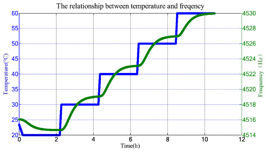
The relationship between the resonant frequency of the HRG and external temperature.
In order to obtain the bias stability of the HRG, the temperature of the HRG in incubator changes according to the temperature change curve in Figure 8. Five groups of experiments were performed to control standing wave at 12.5°, 18.5°, 22.5°, 26.5° and 36.5°. The control force of the HRG in different directions is shown in the Figure 9. The two-axis control forces of the HRG change with the temperature, and it has a clear correlation with the frequency change of resonator from Figure 9. Equation (13) shows that the main sources of change in control forces are frequency, damping and uneven variation. Therefore, instability will be introduced if only the two-axis control forces are used as the bias of the HRG.
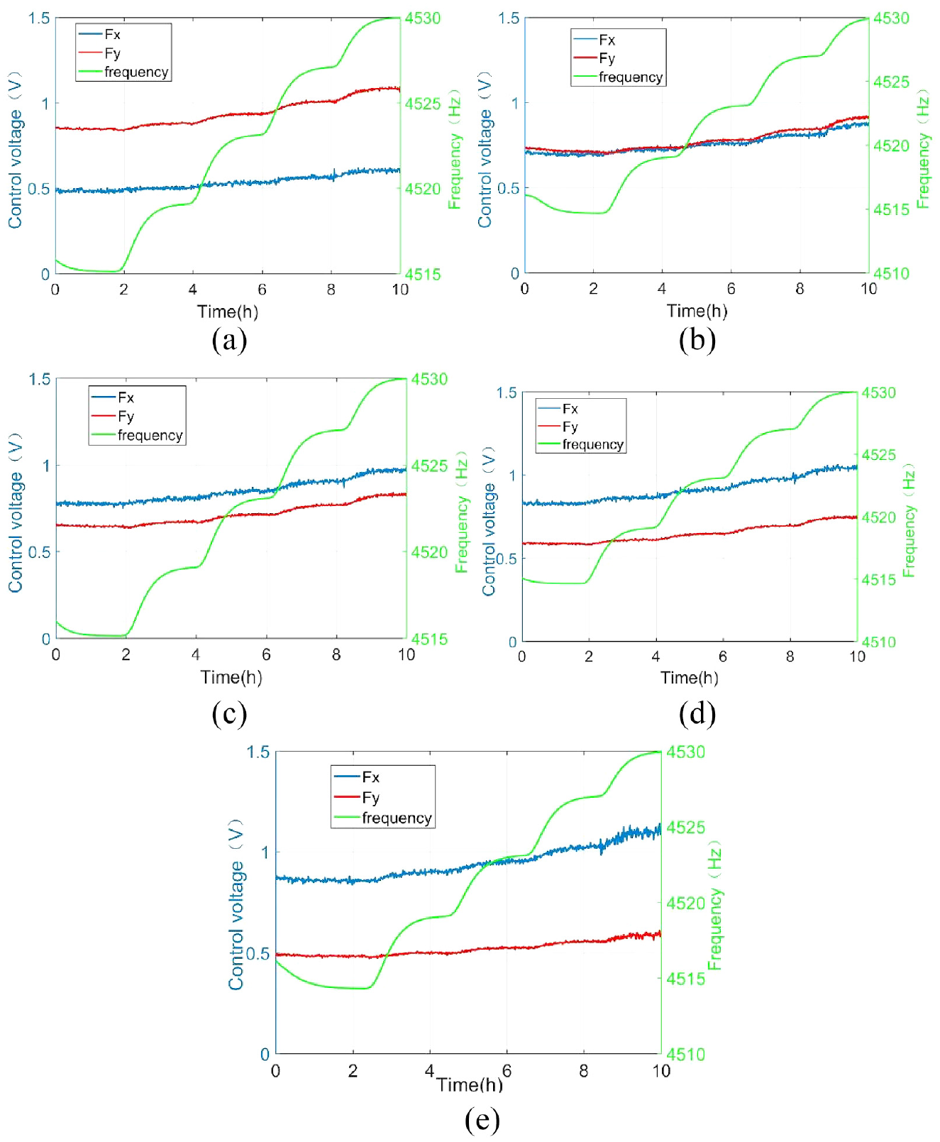
The experimental results of two-axis control voltage variation at different standing wave azimuths and temperature. (
In order to reduce the bias of the HRG, Equation (13) can take
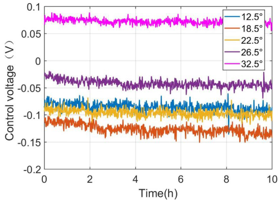
The control voltage of the HRG at different standing wave azimuths.
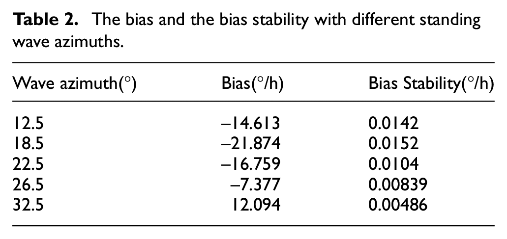
In the temperature range of 20°C∼60°C, the experimental results in Figure 10 are calculated to obtain the bias and the bias stability of the HRG in different orientations as shown in Table 2. When the standing wave azimuth is at 32.5°, the bias of the HRG is 12.094°/h and the bias stability of the HRG is 0.00486°/h, which are obviously better than other azimuths. Compared with the worst standing wave orientation (18.5°) in the experiment, the bias stability of the HRG in the temperature range 20°∼60° are improved by 3 times. Therefore, the bias stability of the HRG can be effectively improved by changing the standing wave azimuth.
The bias and the bias stability with different standing wave azimuths.
Conclusion
The control forces and the bias stability of the HRG at different standing wave azimuths are deduced and simulated in the paper. The simulation results shown that the bias of the HRG will be periodically modulated with the change of the standing wave azimuths. When the standing wave azimuth and the damping axis are aligned, the bias error of the HRG will be greatly reduced, and the bias stability of the HRG will be optimized. The control algorithm and hardware circuit are designed to increase the bias stability of the HRG which affected by the temperature, and the experiments are carried out. The results showed that there are significant differences in the bias stability of the HRG at different stand wave azimuths, and the bias stability of the HRG can be optimized by adjusting the standing wave azimuth to suppress errors caused by temperature.
Footnotes
Declaration of conflicting interests
The author(s) declared no potential conflicts of interest with respect to the research, authorship, and/or publication of this article.
Funding
The author(s) disclosed receipt of the following financial support for the research, authorship, and/or publication of this article: This work is partially sponsored by Program of Shanghai Academic/Technology Research Leader under Project 18XD1421700, the Natural Science Foundation of Shaanxi under Project 2020JM-488 and Shanghai Rising Star Program under 20QA1404300.