
Abstract
Low voltage DC microgrids have been gaining great attention for the integration of renewable energy source and energy storage units, and electronic loads. DC microgrids are commonly controlled using the hierarchical control strategy (HCS) to provide flexible operation in both grid-connected and islanded modes. The HCS relies on proportional-integral (PI) controllers and employs the droop control strategy. To improve the fault ride-through of HCS based extra low voltage DC microgrids, this paper proposes a simple, accurate, and cost-effective current limiting strategy. The proposed control system based scheme modulates the current reference of the primary control level of HCS during an overcurrent condition using the smooth set point automatic adjustment with correction enabled technique. It properly protects the semiconductor switches of interface voltage-sourced DC-DC converters by accurate limiting their inductor currents. The main advantage of the proposed scheme is that it is implemented in the available PI controller based primary control level of the HCS. Also, it does not require the converter and load data. Several case studies performed in MATLAB/Simulink environment are presented to demonstrate the superior ability of this scheme for limiting fault current in different scenarios compared to conventional current limiters.
Keywords
Introduction
Environmental pollution concerns and imminent exhaustion of fossil fuel have led to the increasing integration of low carbon emission renewable energy source (RES) units such as photovoltaic and fuel cell systems.1,2 Conventionally, these units are integrated into the AC distribution network using the multi-stage converters. However, many industrial applications such as aircraft, railway, irrigation, and telecommunication employ DC sources to supply DC loads.3,4 DC microgrid as an important block of the future smart grid is an effective solution to alleviate the technical problems associated with conventional AC microgrid including need for frequency control, harmonic and reactive power issues, multiple stages of power conversion, and complicated synchronization.5,6 Commonly, DC microgrids are managed using the hierarchical control structure (HCS) which provides the possibility of working in both grid-connected and islanded modes of operation.7,8 All three control levels of HCS use the proportional-integral (PI) controllers to regulate either the network voltage in the islanded mode or the injected power to the grid in the grid-connected mode.
A DC microgrid is prone to various disturbances such as short-circuit faults. A severe fault results in the network voltage drop. In this condition, the control system of interface DC-DC converters of RES units increases their injected currents. Due to the low thermal inertia of converters, their injected current should be limited to prevent damage to semiconductor switches. 9 Accurate converter current limiting is crucial to improve the fault ride-through capability of the DC microgrid.
There are several fault current limiting strategies proposed for AC microgrids that can be categorized into two groups: (i) external device based and (ii) control system based current limiters. The operating principle of the first group schemes is to insert a series impedance during a fault condition to reduce the voltage drop in the inverter terminal. 10 High cost, low reliability, and impedance sizing and locating are the main challenges of this group. The second group of the fault current limiting schemes usually regulate the current reference of the inverter control system. Instantaneous saturation limit (ISL) strategy as the simplest scheme of this group prevents the current reference signal from increasing beyond a threshold while in the latched limit (LL) strategy, the inverter current reference is replaced by a predefined current reference and the voltage control loop is opened. 11 The hybrid reference frame limit (HRFL) strategy limits the inverter current by multiplying the current reference by a current limiting factor without opening the voltage control loop. 12
However, the current limiting of DC microgrids has not been adequately addressed yet. In,13,14 the solid-state and chopper based fault current limiters are proposed for DC networks, respectively. However, they suffer from the above-mentioned disadvantages of the external device based current limiters. Similar to AC microgrids, to limit the fault current of DC microgrids using their control systems, the current control loop of the primary level of HPS can be used where the PI voltage controller that provides the current reference for the current control loop is equipped with the ISL strategy. Although the current waveform distortion problem caused by ISL operation does not exist in DC networks, the integrator of PI controller is saturated during a fault and the windup phenomenon occurs where the signal cannot be controlled by the controller when the fault is cleared. To solve this problem, the anti-windup schemes are implemented in the PI controllers. 15 In the conditional integration anti-windup (CIA) scheme, the integration process is stopped during controller output saturation while in the tracking anti-windup (TA) scheme, the difference of actual and saturated controller outputs is fed back through a gain to decrease the integrator input. However, both anti-windup schemes suffer from non-accurate current limiting. To address this problem, a new nonlinear framework is developed in 16 to replace the conventional PI controllers. This limiter is based on inserting an adaptive virtual resistance in series with the converter inductor. However, the complexity of the controller is the main disadvantage of this method. The objective of this paper is to present a control system based current limiting strategy that has both accuracy and simplicity features and can be easily implemented in the available PI based primary control level of extra low voltage DC microgrids HCS. In the proposed fault current limiter, the current reference of the current control loop is dynamically regulated by the smooth set point automatic adjustment with correction enabled (SSPAACE) technique during a fault condition. Specifically, the main features of the proposed method are as follows.
It is implemented in the control system of the DER unit and does not require an extra device;
It accurately limits the DER inductor current during faults; and
It can be implemented in the available PI based primary control level of HCS.
The rest of the paper is organized as follows. Section 2 describes the hierarchical control system of DC microgrids. The proposed current limiter is presented in Section 3. Section 4 is dedicated to evaluating the performance of the proposed method, followed by a discussion in Section 5. Finally, Section 6 concludes the paper.
Hierarchical control structure
Proper control and management of a microgrid and its connection (disconnection) to (from) the main grid are crucial for stable and economical operation. These requirements have different importance and time scale; thus, an HCS is required to satisfy them in various control levels. The conventional HCS of DC microgrids consists of three control levels. 7 The task of the primary control level is to preserve the microgrid voltage stability in the islanded mode of operation. Also, the droop control is usually used in this control level to share the power among parallel converters for preventing the circulating currents. The voltage drop caused by the primary control level is compensated by the secondary control level while the tertiary control level manages the power flow between the microgrid and utility grid. Since the focus of this paper is on the faults in DC microgrids that should be cleared very quickly, the secondary and tertiary levels are ignored in this study because they operate with a time delay due to required communication links.
Figure 1 shows the primary control level of a DC-DC converter, consisting of three control loops. The objective of the outer loop is to share the loads among the parallel converters to prevent circulating current. For this purpose, the droop control strategy is commonly used as 7

where
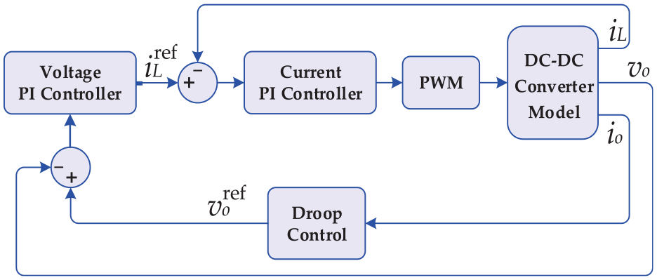
Basic structure of primary control.
Proposed fault current limiter
A prevalent requirement in converter interfaced microgrids is the accurate limiting of converter current to protect the semiconductor switches during overload and fault conditions. The common practice for the current limiting of converter interfaced microgrids is to control the output of the voltage controller because this signal is the inductor current reference
During the normal operating conditions, the PI voltage controller provides the inductor current reference for the current control loop; but when a fault occurs, it is calculated using the proposed strategy. Thus, the modified inductor current reference
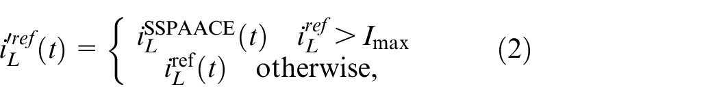
where

where

where

where
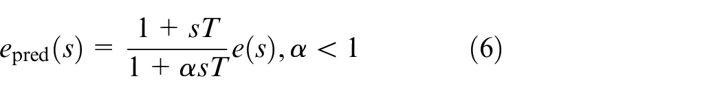
where
Figure 2 shows the schematic diagram of the proposed current limiting scheme. In the normal operating condition, the PI controller of the voltage control loop regulates the converter output voltage
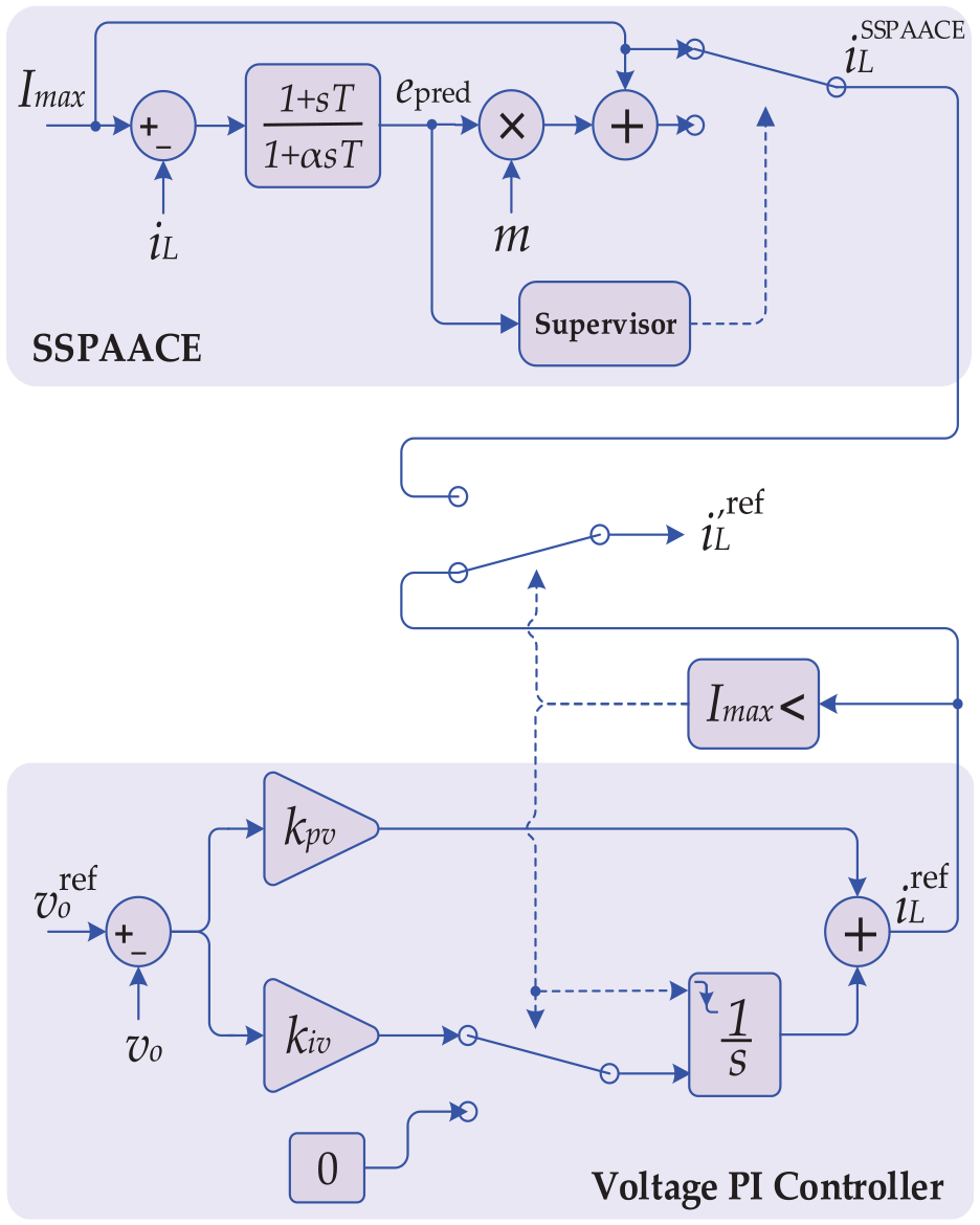
Proposed SSPAACE based current limiting strategy.
Performance evaluation
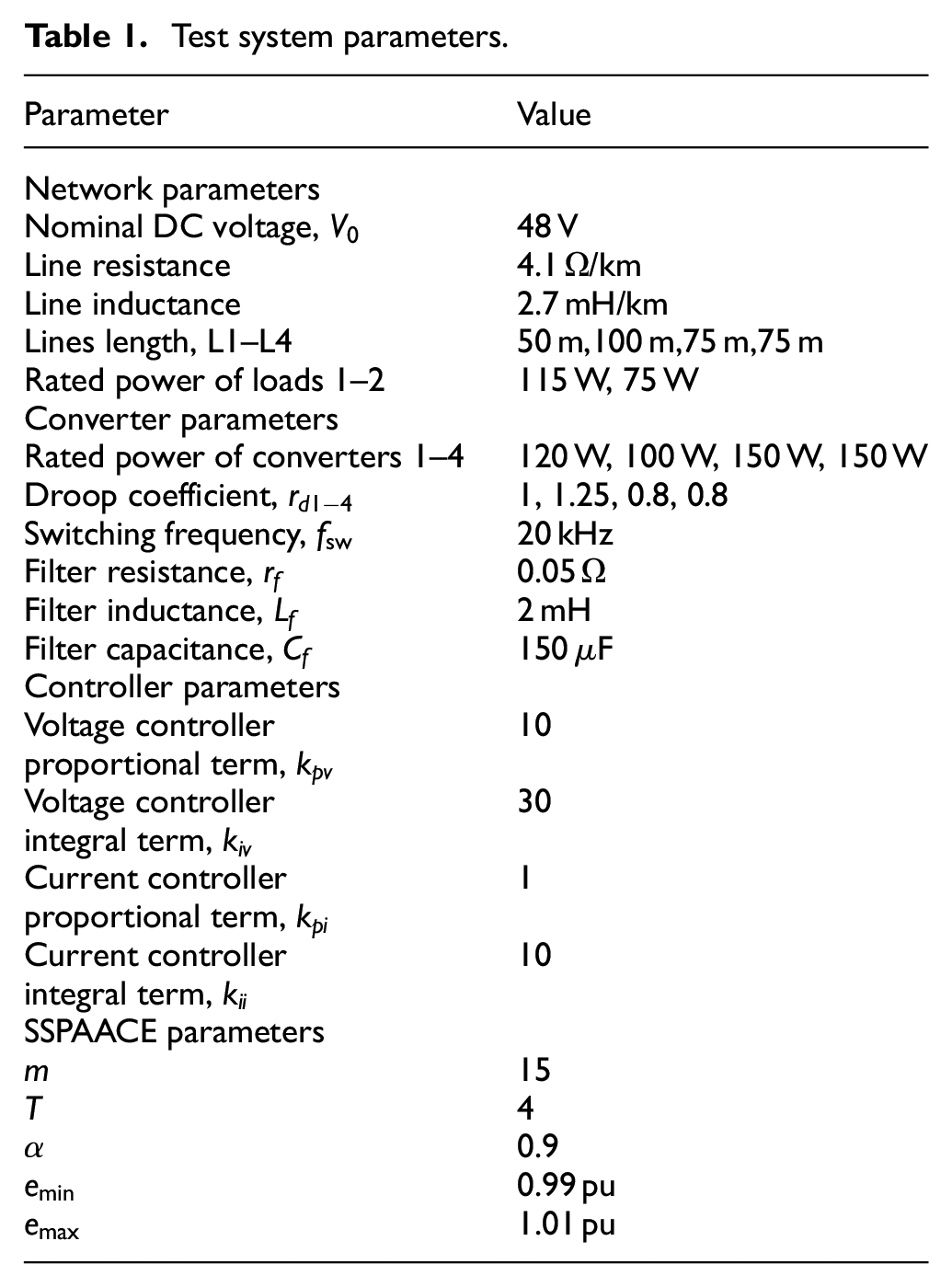
To investigate the performance of the proposed current limiting strategy and to compare it with the conventional current limiters, the test DC microgrid of Figure 3 is simulated using MATLAB/Simulink. This extra low voltage DC microgrid operates in islanded mode and consists of four RESs and two loads. RES1 and RES4 are interfaced with the network through buck converters while the buck-boost converters are used as the interfaces of RES2 and RES3. Due to the short line length and the low voltage level of the network, the capacitance of microgrid lines can be neglected, and consequently, the microgrid lines are modeled by the series RL model. Table 1 presents the parameters of the test system and the tuning parameters of SSPAACE. It should be noted that the PI controller parameters of the primary control level are tuned using the trial and error method. Also, since the DC link capacitance is designed high enough to decouple the primary source dynamics from those of the network,18,19 the dc link voltage will remain almost constant during short transients, and therefore, a constant dc input voltage for the converter is assumed.20,21
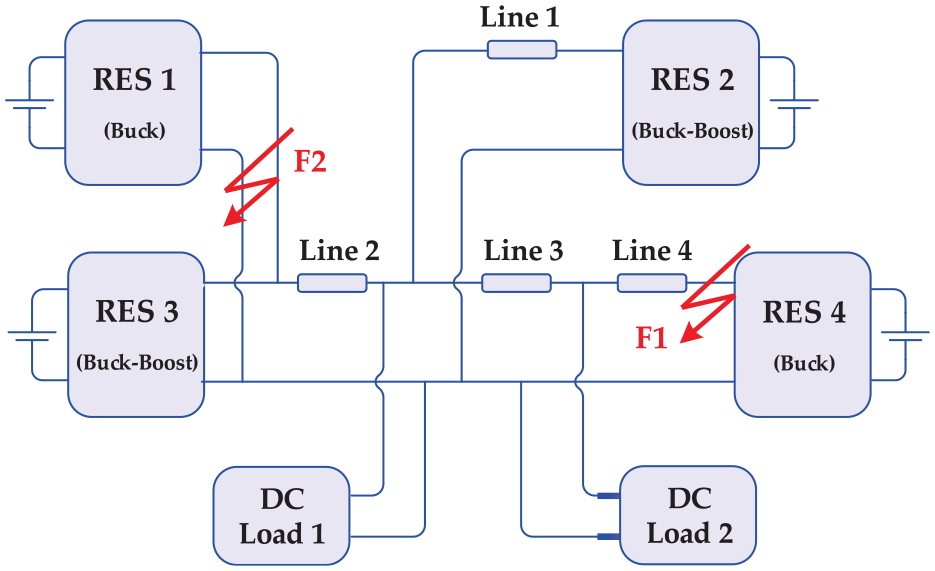
DC microgrid test network.
Test system parameters.
Case 1: Fault condition
In the first case study, a fault with fault resistance of 0.5 Ω is simulated at location F1 in Figure 3 at t = 0.20 s. This fault is automatically cleared at t = 0.25 s. Figure 4 shows the terminal voltage of RESs. In the normal operating condition, the RES voltages are not exactly equal to the reference voltage of 48 V due to droop control operation. When the fault occurs, the voltage drops in various locations of the microgrid and the inductor current reference is increased by the control system. Figure 5 shows the inductor current of all RESs in per-unit, where the per-unit calculation is based on the nominal current of each RES unit. The proposed SSPAACE based current limiting strategy accurately limits the inductor current amplitude at 2 pu. The small overshoot of the response as well as the low settling time during both fault inception and fault clearance instants verify the smoothness and high speed of the proposed strategy.
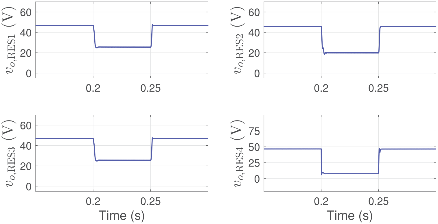
Output voltage waveforms of the RES converters of the study test system during a fault at F1.
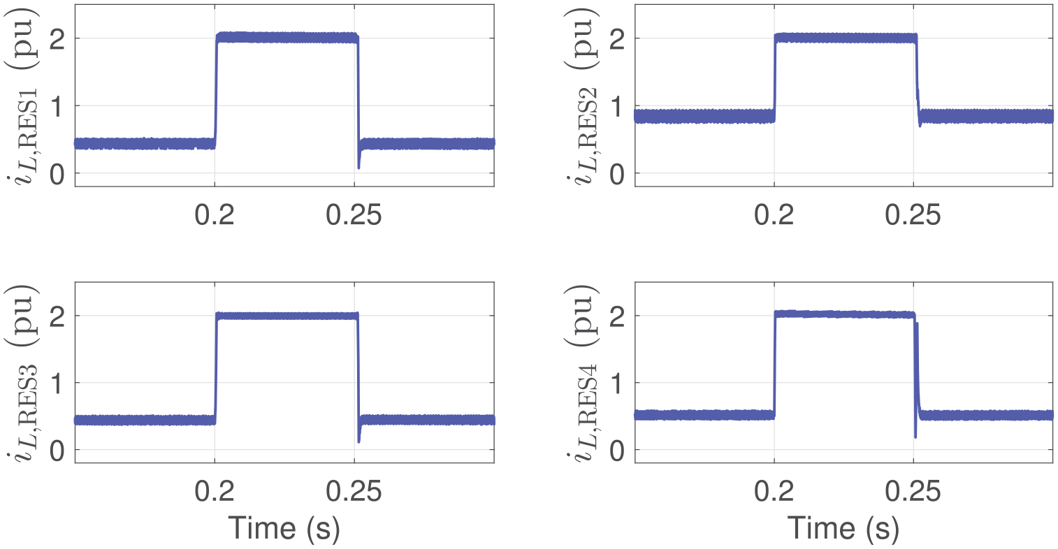
Inductor current waveforms of the RES converters during a fault at F1.
Case 2: Overload condition
In the second scenario, the performance of the proposed current limiter is evaluated during overload conditions. If an overload condition occurs, the proposed limiter is not activated because the overload current is lower than the maximum permissible current
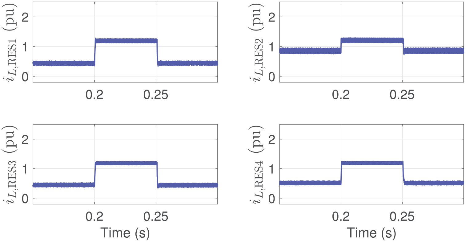
Inductor current waveforms of the RES converters during a load switching with
Case 3: Parameter uncertainty
The next scenario is dedicated to investigating the effect of uncertainty in the microgrid and converter parameters on the performance of the proposed scheme. To this end, the microgrid line impedance, converter filter impedance, and load power are reduced by 20% and previous fault condition is simulated. As shown in Figure 7, the inductor current is properly limited considering microgrid and converter parameter uncertainty.
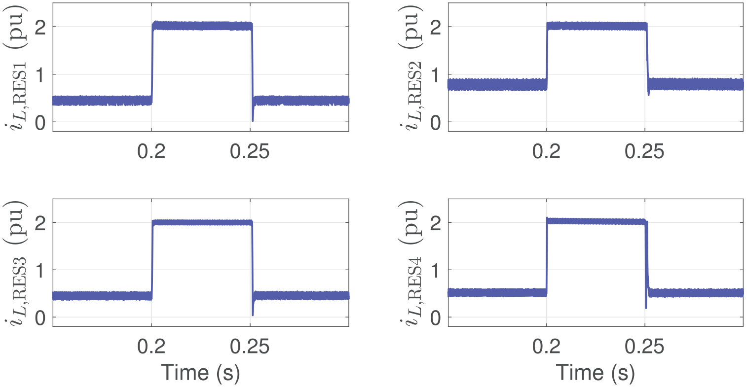
Inductor current waveforms of the RES converters during a fault at F1 considering parameter uncertainty.
Discussion
The main advantage of the proposed current limiter is that it is implemented in the conventional control system of DC microgrids unlike the current limiter presented in 16 where a new control system was developed. To compare the performance of the proposed current limiting strategy with the ISL scheme that can be implemented in the conventional control system, a fault with fault resistance of 0.5 Ω is simulated at location F2 at t = 0.20 s that it lasts for 0.05 s. The PI controller of the voltage control loop is equipped with normal ISL and ISL with CIA schemes and the results are compared with the case of using proposed SSPAACE based current limiting strategy in Figure 8. Both ISL strategies cannot accurately limit the inductor current during the fault condition. Also, in the case of using the ISL strategy without an anti-windup scheme, the inductor current is not recovered after the fault clearance. However, both accurate limiting and proper recovery requirements are properly satisfied by the proposed strategy.
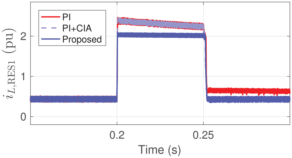
Comparison of proposed current limiting strategy with the conventional ISL schemes.
Consequently, the main features of the proposed current limiter are as follows:
Low cost: Since the proposed limiter does not require an extra device, it is cost-effective.
Accuracy: Unlike the ISL strategies (with and without anti-windup schemes), the proposed limiter accurately limits the current in the specified reference value.
Simplicity: The proposed scheme is implemented in the available PI based primary control level of DC microgrid and thus, there is no need for developing a new control system.
Conclusion
Converter current control during severe disturbances is of great importance to prevent damage to semiconductor switches. A current limiting strategy is proposed for hierarchically controlled extra low voltage DC microgrids. During the normal operating condition, the inductor current reference of HCS primary control level is calculated using the PI voltage controller while during a fault condition, this task is performed using the SSPAACE technique. Also, CIA and integrator reset schemes are employed in the PI voltage controller to enhance the response recovery after fault clearance. In addition to no need for the converter and load data, the proposed approach can be implemented in the commonly used PI based primary control level of the DC microgrid HCS. The simulation results and comparative assessment verify the accurate limiting and proper recovery of the proposed SSPAACE based current limiting strategy. The development of the proposed scheme for limiting solid fault currents can be considered as future work.
Footnotes
Declaration of conflicting interests
The author(s) declared no potential conflicts of interest with respect to the research, authorship, and/or publication of this article.
Funding
The author(s) received no financial support for the research, authorship, and/or publication of this article.