
Abstract
This paper analyzed the noise distribution of three pulleys and one belt system theoretically and experimentally. Aiming at the influence of the tensioner on the transmission noise of the synchronous belt, on the premise of theoretical analysis of the influence of the tensioner on the transmission noise of the synchronous belt, the noise test of the synchronous belt transmission system with and without the tensioner was carried out under the same experimental conditions. Based on the principle of acoustic array measurement, a three-pulley and one belt noise test device was designed. The noise pressure distribution nephogram and amplitude–frequency characteristic curve were obtained by noise tests at different speeds. Through the comparison of the results of two groups of tests, the influence rule of the tensioner on the transmission noise of the synchronous belt was obtained. The results show that the tensioner can effectively avoid the resonance of the synchronous belt, and the noise amplitude of the three-pulley and one belt drive system is 3 dB higher after the tensioner is installed. It provides a basis for vibration and noise reduction of the engine timing transmission system.
Introduction
Synchronous belts are widely used in automobile engine timing transmission system due to the advantages of low quality, low noise and simple structure. With the continuous improvement of automobile vibration and noise performance, a number of studies have been conducted to research on the mechanism and control method of synchronous belt noise.1–3 The previous experiments and analysis simplified the timing belt transmission system into two-pulley model.4–8 However, there are more than two pulleys in engine timing transmission system, and the previous studies ignored the influence of tensioner and idler on timing transmission system. Although the noise type and distribution of two-pulley system are widely known,2,9–11 the influence of the tensioner in the timing drive system on the transmission noise of the synchronous belt has not been fully simulated. A large amount of literature on synchronous belt is available, but most of the literatures are dedicated to two-pulley model.1–16 The research on three-pulley noise has been lacking. This paper investigates the noise source of three pulleys and one belt system, which mainly consists of meshing impact noise, transverse vibration noise and tensioner noise. It aims to determine the position of each kind of noise according to the noise generation mechanism of three pulleys and one belt system and verify it by experiment. The study is conducted to decompose the noise source of three pulleys and one belt system and to elucidate the differences of the noise source under different speeds. The results from different noise patterns and different sources are also compared in terms of the specific characteristics.
To quantify the position of meshing impact noise, transverse noise and tensioner noise, a noise source identification device is designed based on sound array technology. The noise distribution situation can be obtained. To obtain the influence of tensioner on the transmission noise of synchronous belt, the contrast experiment between two pulleys without tensioners and three pulleys with a tensioner was carried out. The result shows that tensioner can change the noise source distribution and noise amplitude of the belt transmission system.
Noise analysis of three pulleys and one belt drive system
The excitation forms of three pulleys and one belt drive system in the transmission process are complex, including the excitation of pulley tooth to belt tooth in the meshing process, and the excitation of tensioner torsion spring to the belt in the transmission process. Thus, the noise source of three-pulley drive system is very complicated. This section analyzes the noise generation mechanism of the three-pulley and one belt drive system.
In the process of meshing, the meshing impact noise occurs between the belt tooth and the pulley tooth. Meshing impact noise mainly focuses on the meshing point of the driven pulleys, which is the point noise source. The meshing impact noise is related to the meshing frequency. The meshing frequency f is related to the speed of the driving pulleys, and the faster of the speed, the bigger the meshing impact noise
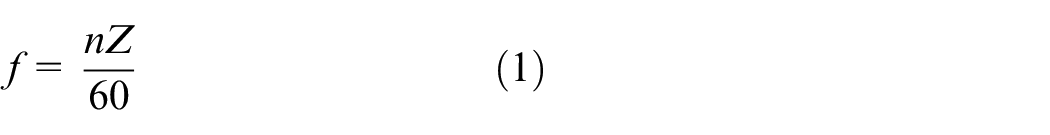
where n is the speed of driving pulley, and Z is the number of driving pulley teeth.
In the three-pulley and one belt drive system, the application of the tensioner reduces the length of the belt, and the damping effect of the belt on the impact force of engagement decreases. Therefore, the application of the tensioner increases the meshing impact noise of the synchronous belt drive.
In the process of synchronous belt transmission, the transverse vibration of the belt will cause vibration noise. When the meshing frequency f is coupled with the natural frequency ωsn of the synchronous belt, the resonance noise will increase obviously. The resonance noise is mainly concentrated on the belt span, which is the line noise source. The calculation equation of natural frequency of transverse vibration is that
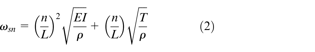
where L is the length of the belt, EI is the bending stiffness of the belt, T is the tension force and ρ is the line density of the belt.
In the three-pulley and one belt drive system, the application of the tensioner reduces the length of the belt, thus increases the natural frequency of the belt. Therefore, the application of the tensioner can change the frequency of resonance noise of the synchronous belt transmission and avoid the resonance noise of the timing transmission system through the arrangement of the tensioner.
During the working process of the tensioner, the components such as the tensioner pulley, spring and bearing will produce noise. In the transmission process, the tensioner will continue to contact with the back of synchronous belt, which will cause relative sliding due to the rotary damping effect, and then cause the friction noise. In order to ensure the tension force of the belt in the transmission process, the spring will continuously exert excitation to the belt, which will cause vibration noise of the tensioner. As a rotating body, the vibration of the rolling body and the inner ring of the bearing produces vibration noise, while the bearing inside the tensioner rotates at high speed.
Principle of sound array technology
In the transmission process, the three-pulley and one belt system includes meshing impact noise, transverse vibration noise and the noise caused by the tensioner, noise sources of which are all different. In order to distinguish the location and radiation performance of each kind of noise source, it is necessary to identify the noise source of the three-pulley drive system by the sound array technology, which include beamforming and near-field acoustic holography (NAH).17–21 When the distance from the sound source to the sound pressure sensor satisfies equation (3), the attenuation of the sound signal to the sound pressure sensor needs to be considered, that is, the near-field acoustic holographic model is needed to describe the propagation of sound signal. The technology NAH is divided into plane NAH, cylindrical NAH and spherical NAH, plane NAH is used to calculate and measure sound sources in this paper
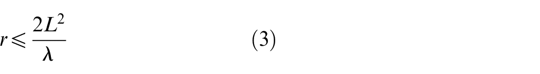
where L is the array length, and λ is the wavelength of sound waves.
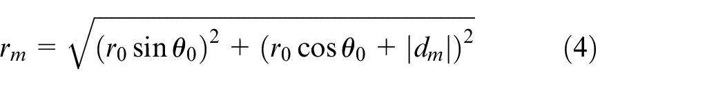
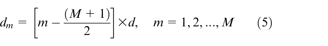
Figure 1 shows the principle of plane NAH technology, where r0 is the distance from the noise source to the array center; rm is the distance from the noise source to the MTH sound pressure sensor; d is the distance between two adjacent sound pressure sensors; dm is the distance from the MTH sound pressure sensor to the array center; and θ0 is the incident angle of the noise source.
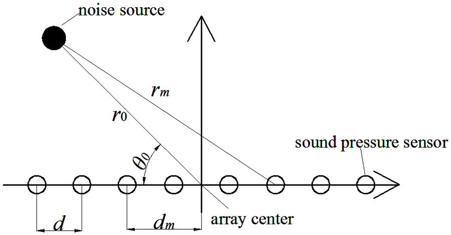
Model of plane NAH.
According to Figure 1, geometric relations can be obtained
The location of noise source can be accurately found through these two parameters. The sound signal Pm(t) collected by the sound pressure sensor is divided into K time periods through the fast Fourier transform (FFT), and the Gmm equation of the cross-spectrum matrix element is obtained as shown in equation (6)
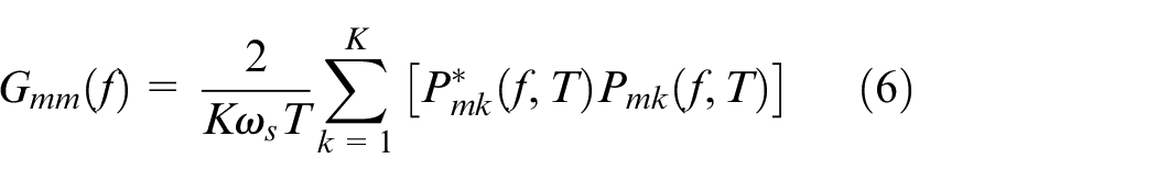
where ωs is the time window constant, T is the length of FFT time and * is the complex conjugate.
The cross-spectral matrix equation composed of Gmm is shown in equation (7)
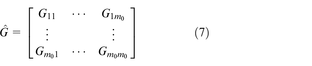
where m0 is the number of sound pressure sensors.
In order to change the signal phase recorded by the sensor and restore the scanning point, a scanning factor em needs to be added
where am is the correction factor of convection refraction, and a am≈ 1 for static measurement; f is the frequency of sound signal; and c is the air propagation speed of sound signal at normal temperature, c≈ 340 m/s.
A vector

Through the guidance factor, the final sound signal is converted into the virtual digital signal of sound pressure sensor

where Pm:n is the virtual digital signal of sound pressure sensor; m is the NO.M sound pressure sensor (MTH); n is the NO.N source point (NTH); and Q is the square of sound pressure at the NTH source point. The product of any two virtual signals of sound pressure sensor is that
Conjugation is used to convert the signal corresponding to the final sound source into real numbers. Substituting equation (11) into equation (7), and let
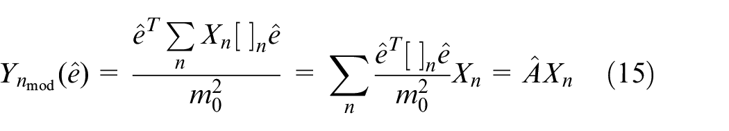
As the final sound source points are all treated as suspicious sound source points, each scanned sound source point may affect the intermediate sound source point. Therefore, each final sound source point needs to be converted into the virtual signal of sound pressure sensor
The virtual signal of sound pressure sensor is converted into the modified intermediate sound source point by guiding factor
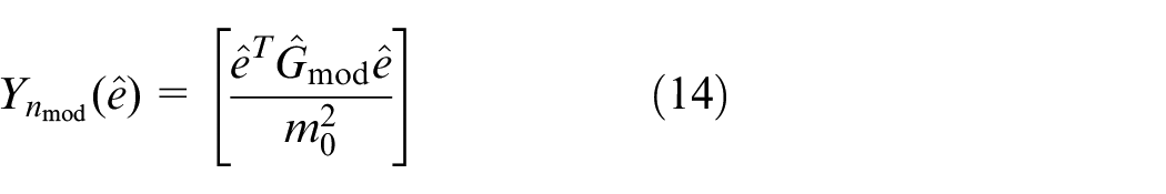
By substituting equation (13) of the virtual signal of the sound pressure sensor into equation (14) of the middle sound source point, the middle point sound source can be obtained
Test apparatus
Figure 2 shows the schematic diagram of the experimental apparatus used to measure the noise distribution of three pulleys and one belt drives, which is composed of the main drive system, the center distance adjustment device, the tension force exerting device, the sound insulation box, the sound array measuring device and the control system. The motor transfers power to the drive shaft through belt drive, and the driving pulley is installed on the drive shaft to drive the driven pulley rotation through the test belt. The main drive system adopts 1.1 kW three-phase asynchronous motor with the maximum speed of 3000 r/min. The driving and driven pulleys used in the apparatus are the same size. The shaft load between the pulleys can be set arbitrarily by setting the heavy loads. The sound array apparatus is mounted on the inner side of the sound insulation box. In order to get the noise distribution of each kind of noise in three pulleys and one belt system, eight sound pressure sensors are placed 50 mm above the pulleys, which form a sound array apparatus and be used to measure the noise distribution of belt drives. The tensioner is installed in the middle of the driving and driven pulleys.
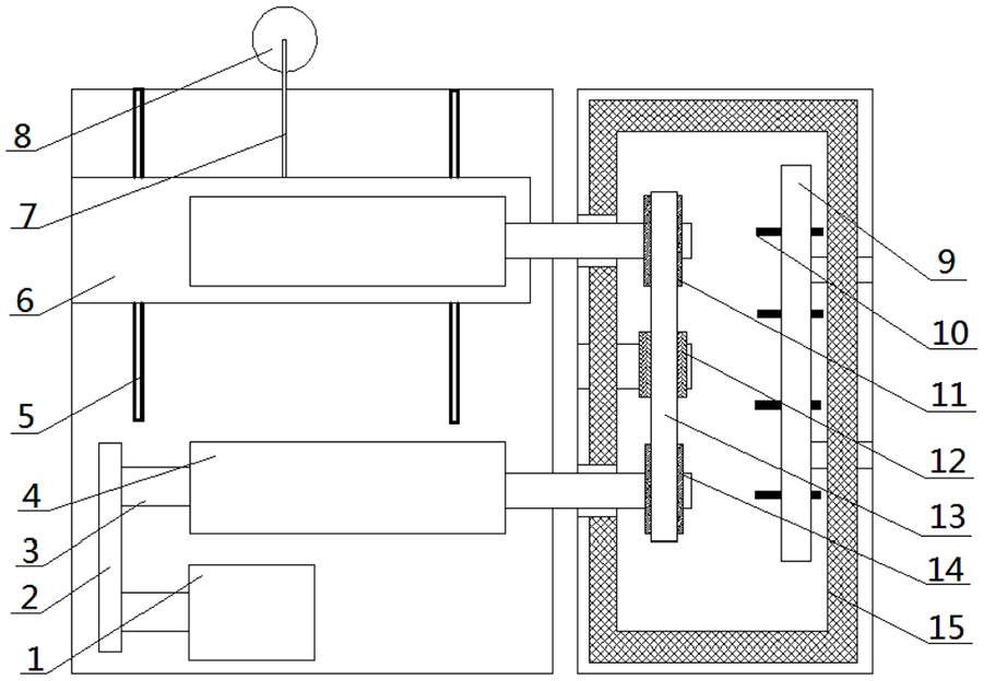
Experimental apparatus for three pulleys and one belt system.
Figure 3 shows the three-pulley and one belt noise source measurement device based on the sound array technology. The type of sound pressure sensor is INV9206. Its measurement sensitivity is −26 ± 1.5 dB. The range of sensor measuring is from 20 Hz to 20 kHz. It is assumed that the middle point of the connecting line of the driving and driven pulleys is the origin of sound array measurement, and the plane of the connecting line of the driving and driven pulleys constitutes the measured surface. The position of the sound pressure sensor is 50 mm away from the measured surface. Sound pressure sensors are arranged in 2 × 4 mode. Row spacing is 150 mm and column spacing is 200 mm. The tested belt is the 99 teeth ZA type synchronous belt. The tension force T = 450 N, the bending stiffness EI = 5430 MPa, width of the belt is 20 mm, line density ρ = 0.89 kg/m. The number of driving and driven pulley teeth is 20, and the center distance L = 0.376 m. The natural frequency of two pulleys and one belt is ωsn1 = 65 Hz, which can be obtained from equation (2). After placing the tensioner, the three-pulley drive system is divided into upper and lower side belt spans. The length of the upper belt span changes little, and the natural frequency is basically unchanged, which is ωsn1≈ 65 Hz. Because the tensioner is placed in the middle position, the length of the left and right sections of the lower test belt are the same, and the natural frequency is the same, which is ωsn2 = 108 Hz.
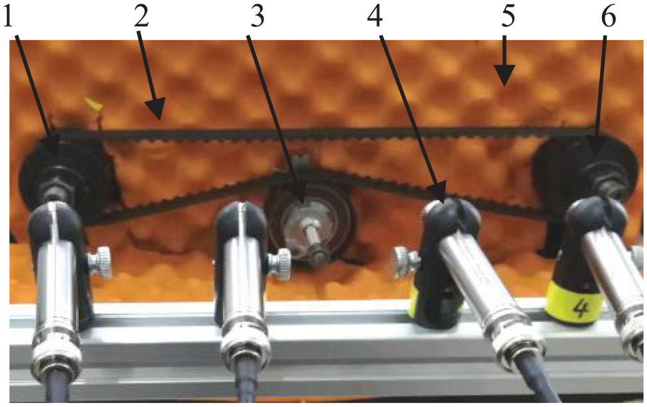
Experimental apparatus of sound array.
Experimental results
Figure 4 shows the measured time domain curve of noise at a speed of 1700 r/min. It can be seen that the amplitude of transmission noise in the three-pulley system is slightly higher than that in the two-pulley system. Figure 5 shows the frequency domain curve obtained after FFT transformation. As can be seen from the frequency domain curve that both of the system produce peaks at their engagement frequency f = 567 Hz and its frequency multiplier, among which the peak value of the system in the area of three pulleys is larger than that of the two pulleys. It proves that the meshing frequency is only related to the speed and the number of driving pulley teeth.
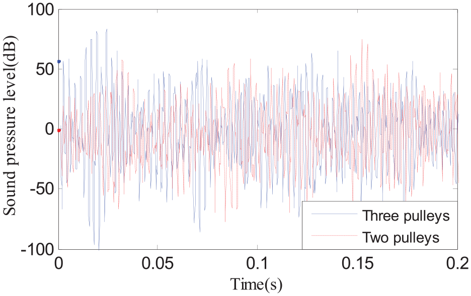
Time domain curve at speed of 1700 r/min.
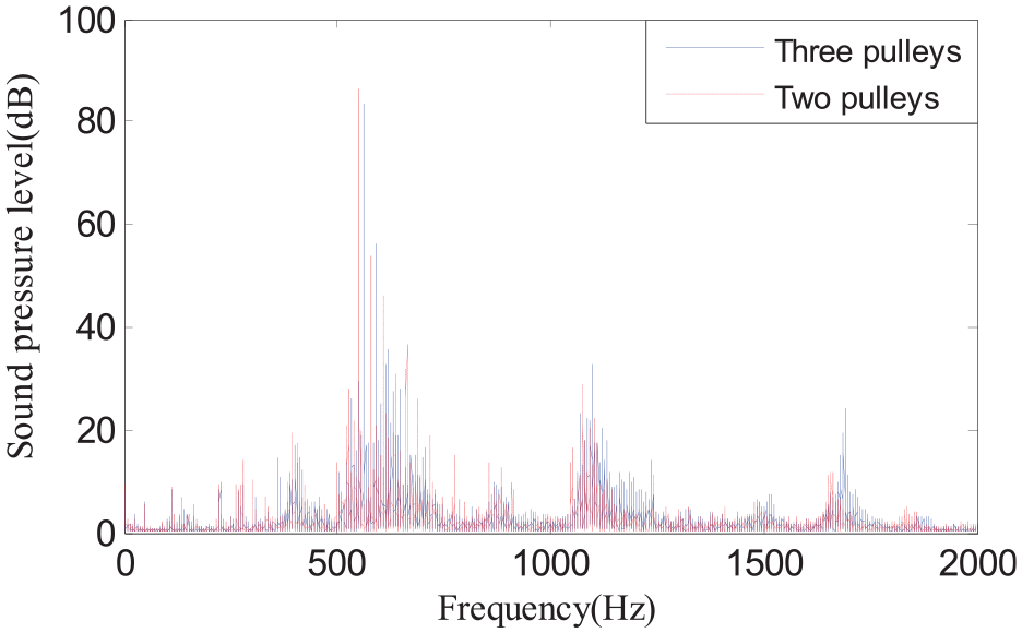
Frequency domain curve at speed of 1700 r/min.
Figure 6 shows the noise distribution situation of two-pulley system at a speed of 1700 r/min, as can be seen from the picture, the noise sources are mainly concentrated at the meshing point of the driving and driven pulley, which is the point noise source. That means the noise mainly consists of meshing impact noise. The noise amplitude of two-pulley system is 75.6 dB. Figure 7 shows the noise distribution situation of three-pulley system at the same speed. The noise sources are also mainly concentrated at the meshing point of the driving and driven pulley. The noise amplitude is 75.6 dB. From the two pictures, it is seen that after the tensioner is applied, the amplitude of meshing impact noise becomes larger.
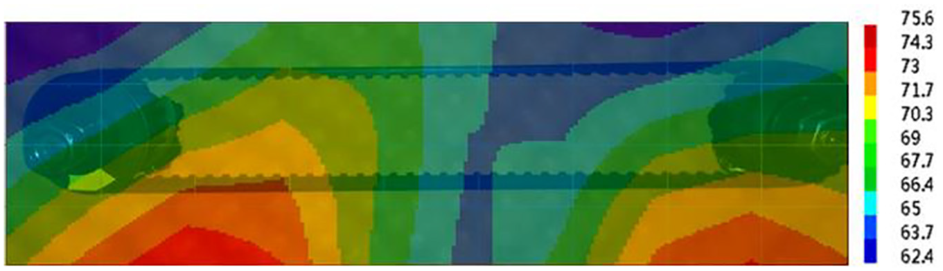
Noise distribution of two-pulley system at a speed of 1700 r/min.
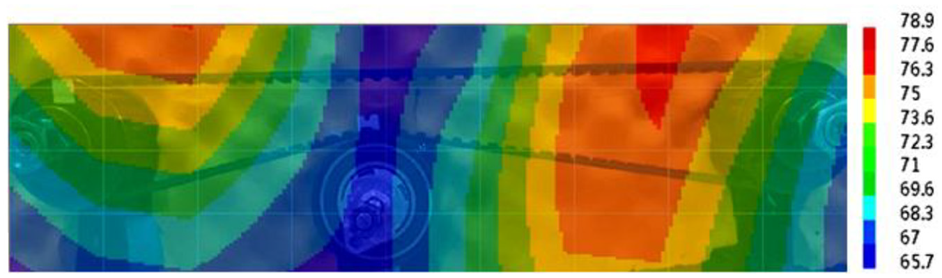
Noise distribution of three-pulley system at a speed of 1700 r/min.
Figure 8 shows the noise distribution situation of two-pulley system at a speed of 1200 r/min, as can be seen from the picture, the noise sources are mainly distributed in the middle section of the belt, which is a linear noise source. That means the noise mainly consists of vibration noise, resonance noise is the main noise source, and the noise amplitude is 83.8 dB. Figure 9 shows the noise distribution situation of three-pulley system at the same speed. The noise source is mainly distributed in the meshing point of the driving and driven pulleys, which is the point noise source. At the same time, there is also a small amount of noise concentration near the tensioner, which is the noise generated by the tensioner during operation. The noise amplitude is 77.2 dB. From the two pictures, it is seen that after the tensioner is applied, the resonance noise of the two-pulley system disappears and the noise amplitude decreases. The experimental results are identical with the theoretical analysis results.
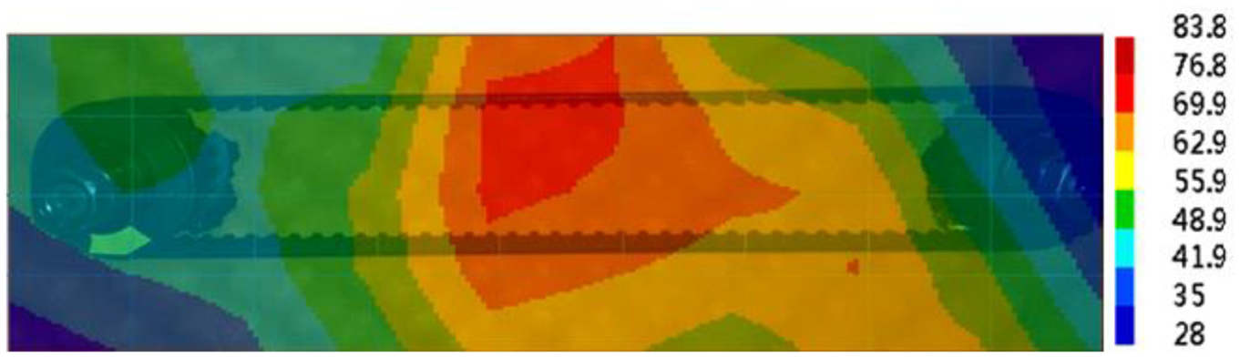
Noise distribution of two-pulley system at a speed of 1200 r/min.
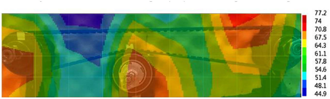
Noise distribution of three-pulley system at a speed of 1200 r/min.
Figures 10 and 11 show the frequency domain curves of both systems at speed of 1200 r/min. From these pictures, it is seen that the peak values of both systems are generated at their meshing frequency f = 400 Hz and its multiple frequency. At this time, the meshing frequency f is coupled with the natural frequency ωsn1. The two-pulley system generates resonance and emits sharp resonance noise, so the noise source is concentrated in the middle span of the belt. While the meshing frequency f is not coupled with the fixed frequency ωsn2 of the three-pulley system, and the noise is still dominated by the meshing impact noise, so the noise source is mainly concentrated on the meshing point.
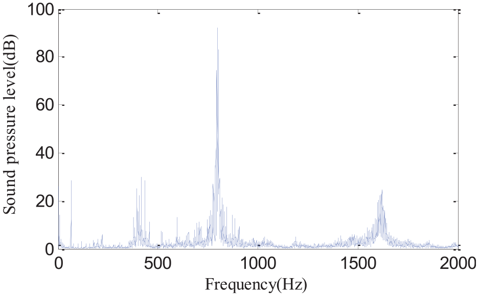
Frequency domain curves of two-pulley system at a speed of 1200 r/min.
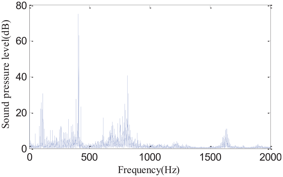
Frequency domain curves of three-pulley system at a speed of 1200 r/min.
Figure 12 shows the noise distribution situation of two-pulley system at a speed of 1550 r/min; it can be seen that the noise source is mainly distributed at the meshing point of the driving and driven pulleys, which is the point noise source. The noise mainly consists of meshing impact noise. The noise amplitude is 76.9 dB. Figure 13 shows the noise distribution situation of three-pulley system at the same speed. The noise source is mainly distributed in the middle of the belt, which is the linear noise source. The noise amplitude is 84.5 dB. From the two pictures, it can be seen that vibration noise is much higher that meshing impact noise.
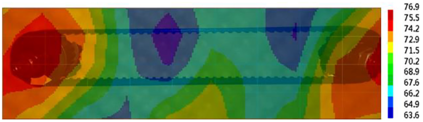
Noise source distribution of two-pulley system at a speed of 1550 r/min.
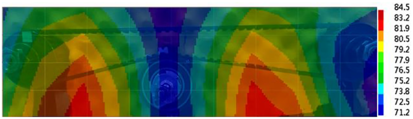
Noise source distribution of three-pulley system at a speed of 1550 r/min.
Figures 14 and 15 show the frequency domain curves of both systems at a speed of 1550 r/min. From these pictures, it is seen that the peak values of both systems are generated at the meshing frequency f = 550 Hz and its multiple frequency. Meshing frequency f is not coupled with the natural frequency ωsn1 of the two-pulley system. At this time, the noise source is mainly meshing impact noise, so the noise source is mainly distributed at the meshing point of the driving and driven pulleys. The meshing frequency f is coupled with the fixed frequency ωsn2 of the three-pulley system. At this time, the three-pulley drive system resonates and produces sharp resonance noise. Therefore, the noise source is mainly concentrated in the middle span of the belt. The experimental results are identical with the theoretical analysis results.
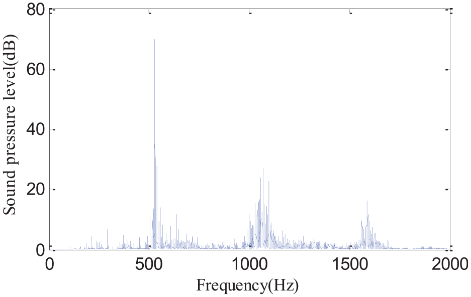
Frequency domain curves of two-pulley system at a speed of 1550 r/min.
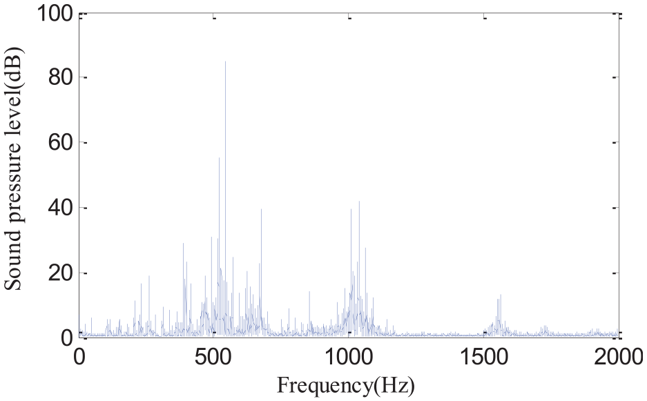
Frequency domain curves of three-pulley system at a speed of 1550 r/min.
Figure 16 shows the change in noise amplitude with the speed of both systems. In order to obtain the obvious influence rule of tensioner on the impact noise and resonance noise of the synchronous belt, the noise amplitude of both systems at a speed of 1000–2000 rpm is analyzed.
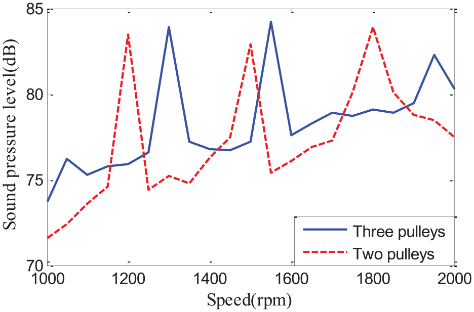
The change in noise amplitude with the speed of both system.
It can be seen that, when the speed is 1000 r/min, the noise amplitude of the two-pulley system is 71.9 dB, and that of the three-pulley system is 74.1 dB. When the speed is 2000 r/min, the noise amplitude of the two-pulley drive system is 76.5 dB, and that of the three-pulleys drive system is 79.3 dB. In the non-resonant region, the noise amplitude increases with the increase in speed, and the noise amplitude of three-pulley system is about 3 dB, which is higher than that of two-pulley system. In the resonance area, two-pulley system occurs at a speed of 1200, 1500 and 1800 r/min, while three pulleys occur at a speed of 1300, 1550 and 1950 r/min. The resonance of the two system is different in speed. This is because the natural frequency of two-pulley system is ωsn1 = 65 Hz, and that of three pulleys is ωsn2 = 108 Hz. As long as the natural frequency ωsn and the meshing frequency f are coupled, the resonance occurs.
Conclusion
The experimental apparatus of three pulleys and one belt system was designed and compared experimentally with two-pulley system with respect to noise. From the results of these comparisons, the following conclusions were obtained:
The application of tensioner in three-pulley and one belt system reduces the belt span; thus, the natural frequency of the belt increases and the speed of resonance noise changes.
In the case of 1700 r/min, the noise distribution of both systems is mainly distributed in the meshing point of the driving and driven pulleys, which is the point noise source. That means the noise of both system mainly consists of meshing impact noise, while the noise amplitude of three-pulley is about 3 dB higher than that of two pulleys.
In the case of 1200 r/min, the noise distribution of both systems is different. The noise of two-pulley system mainly distributed in the middle of the belt, which is a linear noise source. That means the noise mainly consists of vibration noise. While the noise of three-pulley system is mainly distributed in the meshing point of the driving and driven pulleys, which is the point noise source. That means the noise mainly consists of meshing impact noise. That is to say vibration noise can be avoided by applying a tensioner.
The noise amplitude of both systems at a speed of 1000–2000 r/min is analyzed. The meshing impact noise of three-pulley system is 3 dB, which is higher than that of two-pulley system. In the resonance area, two-pulley system occurs at a speed of 1200, 1500 and 1800 r/min, while three pulleys occur at a speed of 1300, 1550 and 1950 r/min, which means the occurrence of resonance noise can be changed by applying the tensioner.
Footnotes
Acknowledgements
The authors thank Jilin Provincial Development and Reform Commission (2019C040-1) and Changchun Science and Technology Bureau (18DY031) for their supports in this study.
Declaration of conflicting interests
The author(s) declared no potential conflicts of interest with respect to the research, authorship, and/or publication of this article.
Funding
The author(s) received no financial support for the research, authorship, and/or publication of this article.