
Abstract
With the application of digital information technology and communication technology, industrial intelligence and integration also began to develop rapidly, and the importance of the research on bus communication in industrial control communication also increased. As the first international bus standard, PROFIBUS has been widely used in the field of industrial control; in recent years, it was mainly used to connect devices to the control layer and convert data through token transmission. Based on the understanding of the transmission mechanism of PROFIBUS fieldbus protocol, this article carries out a simulation study on its communication performance. Through analysis of the data link layer, changing the target token cycle time (high and low priority) and random setting each site message number, as well as the number of master station and slave station, how the main token latency and packet loss rate and efficiency of bus affect the change of performance parameters was observed. For multiple communication systems, the relationship between the address value on the main token ring and transport performance is found by experiments on the site address value on the main token ring and the target token cycle time value. Finally, the scheduling algorithm is applied to the communication scheduling of PROFIBUS fieldbus. The results confirm that the scheduling algorithm has better transmission efficiency than the traditional MAC media access protocol under the condition that the load rate does not exceed 100%, which makes up for the shortcomings of the original PROFIBUS bus system and makes the communication performance better.
Introduction
The distributed control system is gradually formed in the field of industrial control. From the initial development to the present, distributed control system has experienced five stages of development: start-up, maturity, openness, integration, and synthesis. 1 With the continuous expansion of industrial control system, the importance of system integration and the improvement of communication transmission efficiency is increasing. By by digital communication technologies, it can realize the convenient real-time observation of the field signal. At the same time, the application of fieldbus enables the smart devices to be directly added to the field devices, which greatly improves the convenience of equipment installation. Based on the fieldbus system, the field equipment can be connected together in two transmission lines, and the users can independently design and choose the modules for installation according to the requirements.
PROFIBUS media access method is a deterministic media access control method. The media access method is a simplified token protocol. The protocol specifies that the node which holds the token has the right to transmit the message. In the control system configuration, the determined master stations together constitute the token ring network, and the token information is transmitted in two directions on the token ring network. Each site can detect messages sent by other sites during each transmission without conflicts, which is more suitable for real-time application environments. PROFIBUS is widely applied in the control field, including power, process control, environmental engineering, processing, and other industries. 2 Systematically in this article surrounding the main communication transmission process simulation transmission experiment, around the fieldbus communication message transmission relationship between the process parameters were analyzed, and through the packet loss rate, transmission efficiency, token waiting time real-time performance indexes provide the theoretical basis for the optimization improvement of system “was changed into” In this article, the communication transmission simulation experiments was carried out, and some important parameters affecting the message transmission,such as packet loss rate, transmission efficiency, token waiting time, were analyzed to provide the theoretical basis for the optimization improvement of system. The real-time communication simulation process designed for the data link layer provides the data and the theory of experience; it provides a certain theoretical basis for the practical engineering application of PROFIBUS field bus the field of industrial control. The conclusion of this article can be used by the practical engineering applicator or operator in the configuration and parameter setting of the bus control system.
PROFIBUS communication protocol
According to the number of master stations, PROFIBUS fieldbus control system can be divided into a single-master station communication system and multi-master station communication system. Token ring refers to a kind of transmission binding between master stations in a multi-master station system. The primary station on the ring carries out token transmission according to the address value of the primary station, while the primary station holding the token can carry out data transmission. In a single-master station and multi-slave station system, there is no token transmission, and data transmission is conducted between the master and slave stations according to the question and answer mechanism.
Protocol introduction
PROFIBUS fieldbus is a simplified token bus that integrates the advantages of bus and ring bus. PROFIBUS is a bus in the physical layer, and a ring in the data link layer, that is, a token type. 3 This integration mode enables the physical layer, that is, the field equipment, to increase or decrease at any time for convenient operation. In data transmission, the bandwidth is not limited.
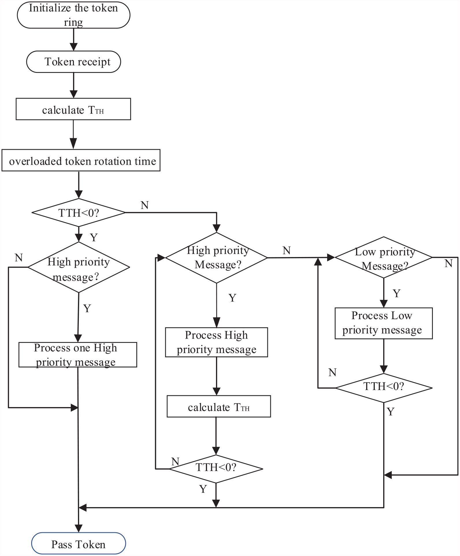
The bus system adopts mixed-media access to achieve controlled media (MAC) access. 3 The PROFIBUS protocol in German standards stipulates that the information transmitted by each station is divided into two categories: high priority and low priority (including periodic information, aperiodic information, and management information). MAC is a simplified TT protocol for PROFIBUS fieldbus. Fieldbus nodes are divided into master and slave stations. 4 Only the master station node can receive the token, and all the master stations constitute a ring network to connect the master stations on the bus. The master station on the token ring network transfers tokens according to the size of the address value.
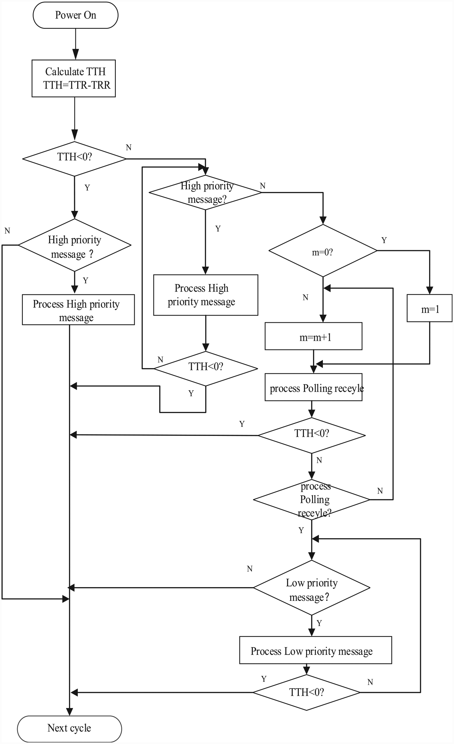
A significant feature of PROFIBUS’s simplified token protocol is that it does not limit bandwidth, that is, it does not guarantee the allocation of fixed time for transmission information. 5 When the token is initialized, each master station on the token ring is assigned an address, and the next state of the token ring depends on the address value of the primary station. According to the size of the set target token cycle time value, the token carries out the polling transfer operation between each primary station according to the link table of the primary station. The master station holding the token can transmit the master and slave station information. Messages transmitted are classified according to their high and low priority, and messages of the same priority are processed on a first-in-first-out basis. The MAC media transmission mechanism can briefly describe the node with the smallest address of the primary station and create a token after power on, which is passed from a primary station to the next station. 6 The token receiver has the right to transmit the message within the specified token holding time. The node with the token will transmit the token to the next station in the link table of the primary station after transmitting the message.
There are three main parameters in the PROFIBUS performance analysis. The first is the target token cycle time
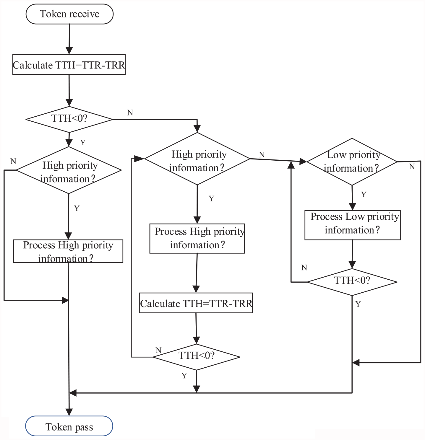
PROFIBUS media access flowchart.
Experimental parameters
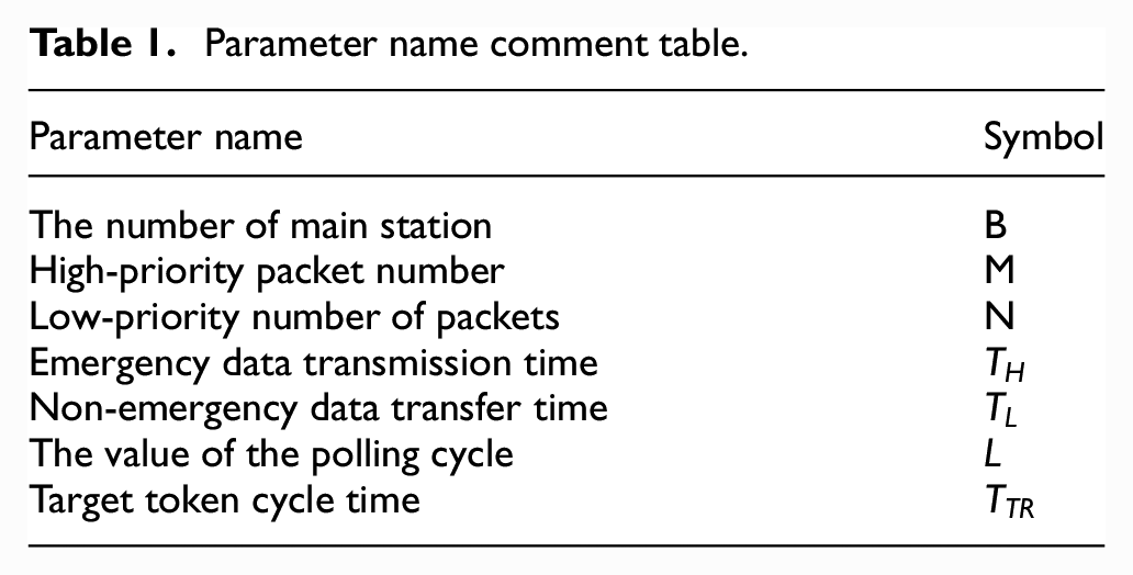
At the time of programming, the parameter names are defined as in Table 1.
Parameter name comment table.
Communication performance evaluation index
Target token cycle time
Node waiting time
Packet loss rate
Note:
Bus transmission efficiency
where
Single-master and multiple-slave communication model
A typical PROFIBUS DP system with a single-master station is mainly controlled by a programmable logic controller or a single host (central controller). According to the token-type transmission mechanism of PROFIBUS bus, since tokens are only transmitted between master stations when the system works, there is no token transmission in the single-master station system, and only the master-slave transmission mechanism is studied. During the cycle time of a single target token, the master station USES the network to send a query frame to the slave station, and the slave station answers. In the communication process, the transmission efficiency is determined according to the number of messages on the node and the transmission mechanism. Different loads and different target token cycle time Settings have a certain impact on transmission performance.
The construction of simulation model
Based on the VS2010, communication simulation process is divided into three parts: data acquisition, data transmission and data result processing. In the actual system, the transmitted data is mainly sent to the site from the controller of the upper level, and the number of messages received by the site or the detector can detect the data in real time. 7 There is some uncertainty in the field data.
In order to better match the actual bus communication in the simulation process, random functions are used in the data input module to generate random data in each polling calculation. Performance is characterized by the message length of each station with no memory and random arrival. Here, the random function is selected and the seed number is set to perform the random simulation, controlling the random number to meet the probabilistic events in the specific region and ensuring sufficient randomness.
The core protocol transmission mechanism code is as follows
for (int i = 0;i; i < N;i ++)
{
if(sum <= T) {
sum = sum + v1[i]*t;
if(sum <= T)
v2.push_back(v1[i]*t);
else v2.push_back(T— sum—1(i)
}
else
v2.push_back(t);//
}
Experimental analysis
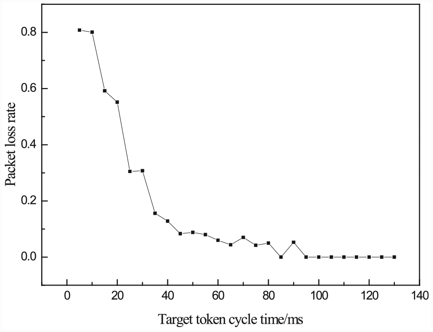
From the experimental simulation, input/output data and the simulation of the actual number of message transmission to calculate the packet loss rate,the average packet loss rate in 20 polling cycles for the single-node, according to the type (3-3). The diagram was shown as Figure 3.
With the increase of the target token cycle time, the packet loss rate of node transmission presents a decreasing trend in a large range. According to the different polling tasks of each node in actual field engineering, the efficiency of node message transmission will have a non-linear change. Within the allowable range of data error, according to the variation range of Figure 4 curve, it can be concluded that the packet loss rate of bus communication is inversely related to the size of the target token cycle time. With the increase of the target token cycle time, the number of packets that can be transmitted by each station increases, and the packet loss rate decreases accordingly. However, if the target token cycle time is too large, the transmission efficiency may decrease. Therefore, setting the target token cycle time correctly is the key problem in the circular transmission.
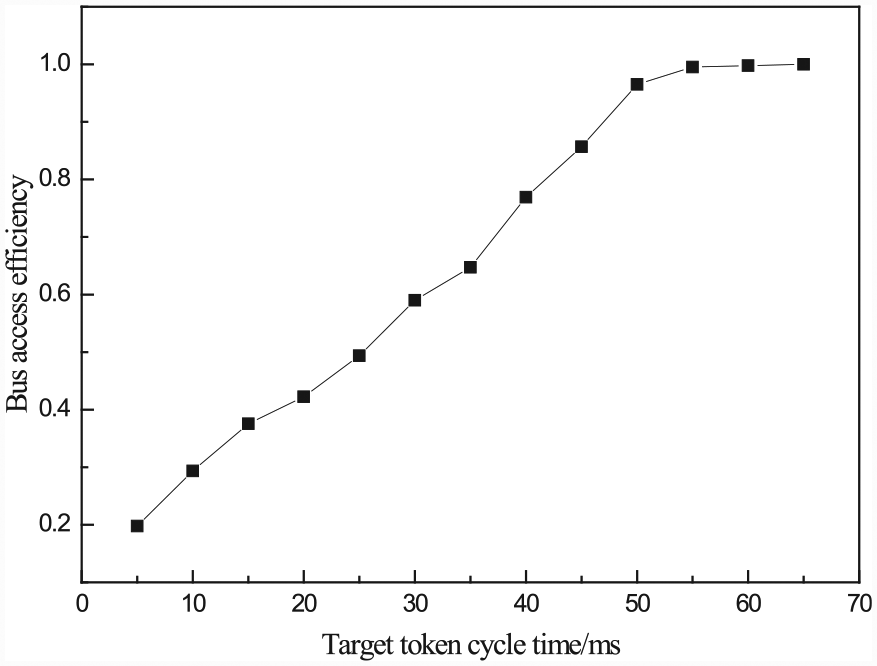
As can be seen from Figure 4, the bus access efficiency increases with the increase of the target token cycle time. Within a certain range, the two are in a positive linear relationship. As the target token cycle time increases, the token wait time for each node and the data transferred amount for each node increase. When the target token cycle time is large enough to complete the full transmission of periodic data and non-periodic data of each node, all messages of the node can be transmitted, but in this case the waiting time of the node is long and the communication timeliness is low.
As can be seen from Figure 5, as the number of slave stations increases, the load data increases, or the packet cycle becomes longer, the packet loss rate increases gradually in a large range during single-cycle polling. This is also a phenomenon of increasing message transmission delay, because in practical engineering applications, reasonable load should be carried, so that the transmission efficiency and packet loss rate can be within a reasonable range.
Multi-master fashion
In PROFIBUS bus control system, each node carries out data transmission and command transmission through the bus as shown in Figure 2. In order to ensure the reliability and timeliness of transmission, the communication between sender task generation and receiver task acceptance and application task is time-constrained. Different conditions were applied to the message to be transmitted conditions in the process of the whole transmission delay, in a polling total time delay is called measurement period, 8 also some scholars abroad as end to end communication time delay, 9 specifically refers to the master-slave site a switching cycle, data transmission, and control cycle is mainly produced by information delay, packet queuing delay, data transmission delay, send delay composition as shown in Figure 6.10–12
Information delay: the time for the sending task node to generate the application task and add the task to the transmission queue is mainly affected by the performance of the sending end.
Message queuing delay: after a message arrives on the queue, it waits for the arrival of the token and is processed. This delay is mainly affected by the information transmission mechanism and load size.
Data transmission delay: the time taken from the sender to the receiver to transmit the message, which is mainly affected by the communication rate and the length of message frames, that is, the single message transmission cycle.
Transmission delay: the time consumed by data processing and forwarding, mainly refers to the time occupied by message decoding and reassembly.
PROFIBUS single-master station information transmission process diagram.
The relationship between bus access efficiency and target token cycle time.
Graph of average packet loss rate and target cycle time.
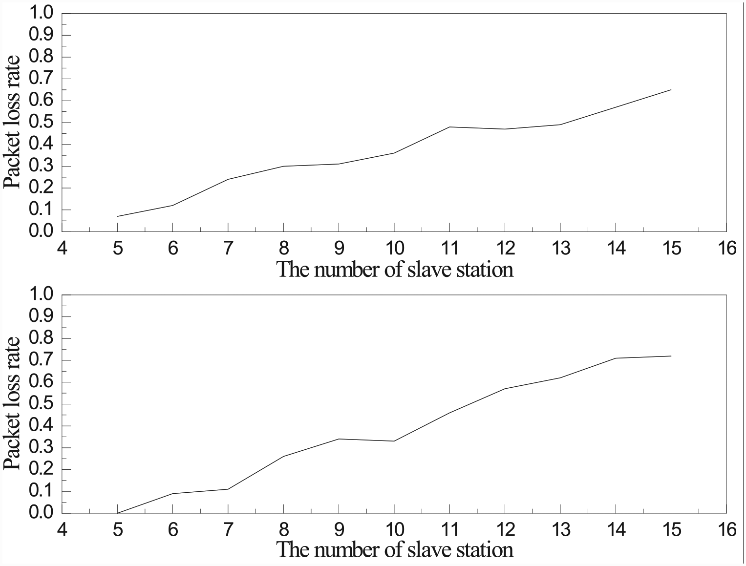
The relationship between load rate and packet loss rate.
Flowchart of data transfer logic of multi-master station system.
Slave communication model
Experimental analysis
Experiment 1: B = 15, TH = 0.5 ms, TL = 1 ms, L = 10. The arrival amount of high-priority message flow is randomly distributed in [0,2]. The arrival amount of low-priority message flow is randomly distributed in [0,10]. Run the program, write down the token waiting time of a node, and sort out the results as shown in Table 2.
Run output value.
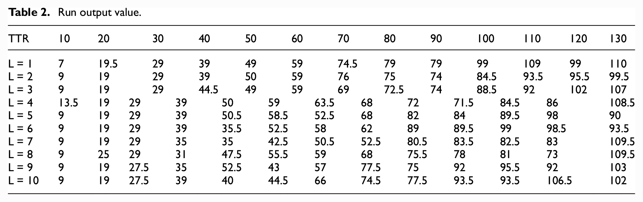
According to the above results, the cyclic relationship between node token waiting time and target token is drawn, as shown in Figure 7 below.
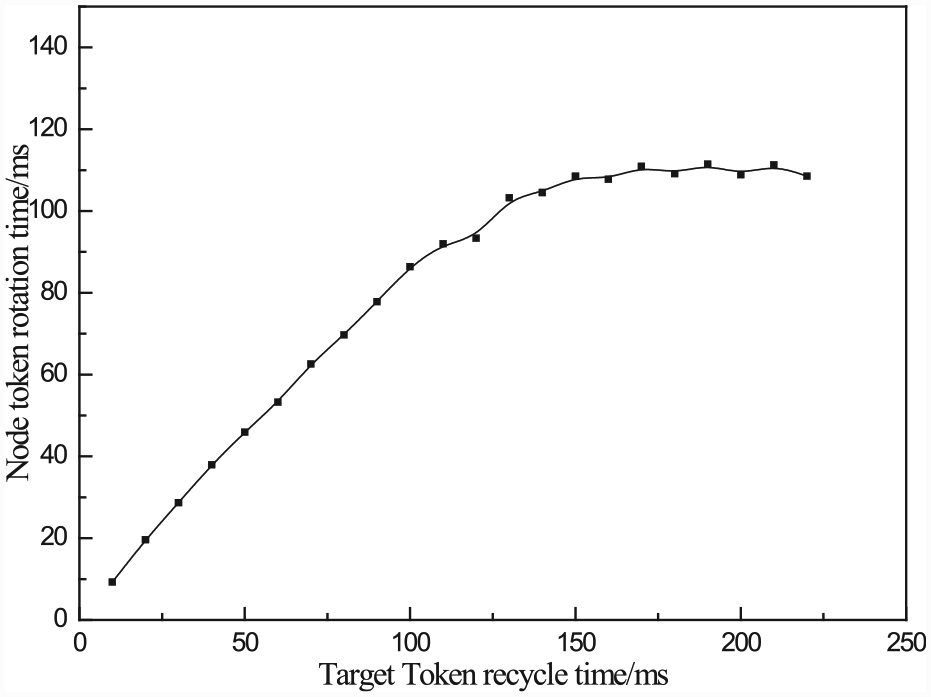
Diagram of token cycle time versus token wait time.
As can be seen from Figure 7, in the case of fixed address value, with the increase of the target token cycle time, the waiting time of single-node token gradually increases. When the target token rotation time increases to a certain extent, the waiting time of node token remains unchanged within a small range.
Experiment 2: B = 15, TH = 0.5 ms, TL = 1 ms L = 10. The arrival amount of high-priority message flow is randomly distributed in [0,2], while the arrival amount of low-priority message is set at a large value. The running program analyzes the experimental results and draws them as shown in Figure 8.
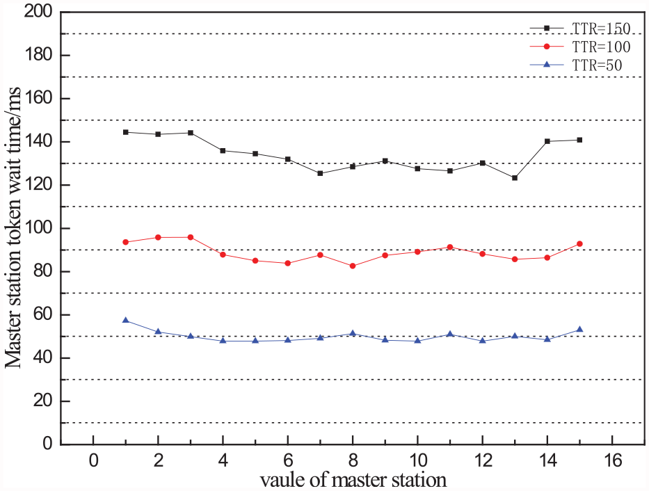
Diagram of the relationship between the primary site address value and token wait time.
Figure 8 shows the relationship between the primary site address value and the waiting time of tokens. When the target token cycle time is the same, the waiting time of each primary site token is different.
In order to observe the rule more intuitively, experiments were carried out to calculate the average waiting time of each node token, which is represented in Figure 9.
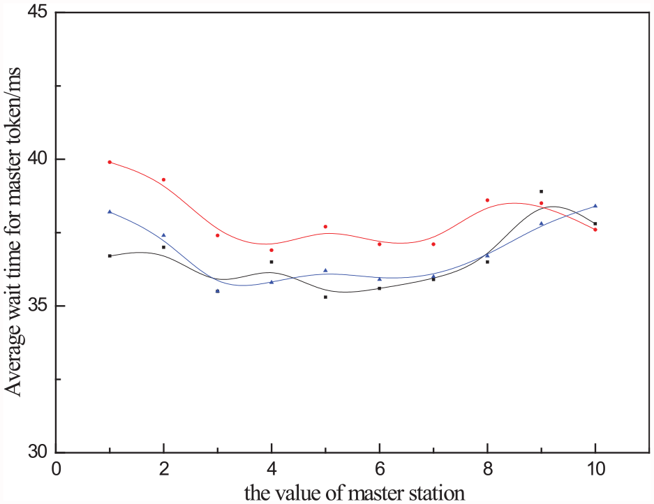
The relationship between the average wait time of the master station token and the master station address value.
As can be seen from Figure 9, the token ring network’s intermediate site token wait time is shorter with the same load rate.
PROFIBUS communication performance optimization
PROFIBUS fieldbus is a typical real-time system.13–15 As for industrial network communication, real-time mechanism does not mean only high speed. It means that messages can be transmitted before their deadline, which is reflected in the boundedness of periodic information transmission. It can be seen from the simulation model in the previous section that the station message priority can only be high or low. High-priority message refers to those more particularly high real-time performance of safety management related message, in the practical engineering application, the quantity is small low-priority message is much and no class distinctions, Whether it can be transmission or not is entirely determined by the time the master station holds the token completely.16,17For complex multi-master station systems, the control performance of different controllers is different and the target token cycle time set by manufacturers is also different. When constructing a multi-master station for configuration, it becomes more difficult to set the target token cycle time. If it is so small, only high-priority messages can be transmitted, while low-priority messages cannot be sent or even lost, which affects the real-time performance of system communication. If it is so large, the overall transmission efficiency of the system will be lower.11,18 The simulation results in section 3 also verify this point. Faced with the above problems, it is necessary to improve the scheduling method of priority of PROFIBUS communication system information, so as to improve the real-time performance of PROFIBUS fieldbus.
Communication simulation based on scheduling algorithm
This article combines the earliest information scheduling algorithm (EDF scheduling algorithm) to improve the communication and transmission process of PROFIBUS fieldbus.
EDF scheduling algorithm rules
EDF scheduling algorithm is also known as the earliest deadline information scheduling algorithm. 11 It is an algorithm to determine the priority order according to the deadline of the transmission task. The deadline is the maximum time from which a message can be effectively executed.19–21 Absolute deadline is the difference between the time a message is sent and the maximum time it can be effectively responded to. In a single queue, the message transmission sequence is sorted by the response deadline time of each arrival message. In each transmission, the message with the earliest deadline date is allowed to work first to ensure the real-time performance of bus transmission to the greatest extent. 22
In the EDF scheduling algorithm, the priority definition assignment of message transmission is defined as

where
PROFIBUS simulation model based on EDF algorithm
In order to ensure the real-time performance of PROFIBUS communication, messages in PROFIBUS control system are classified according to the real-time performance.23,24 During transmission, messages transmitted by PROFI BUS are divided into the following three types:
Strong high-priority message: It mainly refers to high-priority message under MAC mechanism. It refers to the system to ensure the safe operation of information security instructions. It is characterized by strong real-time performance and no delay is allowed. Once the delay occurs, the system will be harmed greatly.
High-priority message: It mainly refers to the message with earlier message deadline date and shorter message transmission cycle. It is characterized by strong real-time performance, small allowable delay range, and significant impact on system communication performance.
Low-priority message: It mainly refers to messages such as information management and command report, which mainly refers to messages that arrive late in the deadline. The characteristic is that there is no real-time delay is allowed, and the delay will not affect the communication performance of the system.
Experimental analysis
In the simulation dealing with two-dimensional array simulation high and low-priority message arrived, the first column of the array represents the message transmission time and the second column represents an array of the message transmission deadline queue. On the basis of the second column in the array, relative deadline decided the size of the message queue within the message priority sorting. Because EDF scheduling algorithm is mainly used to improve the low-priority message efficiency, a low-priority message queue should be considered as shown in Figure 10. The arrival message data conforms to the form of one-dimensional array. M stands for the high-priority message queue, while N stands for the low-priority message queue. The data distribution is shown in Table 3.
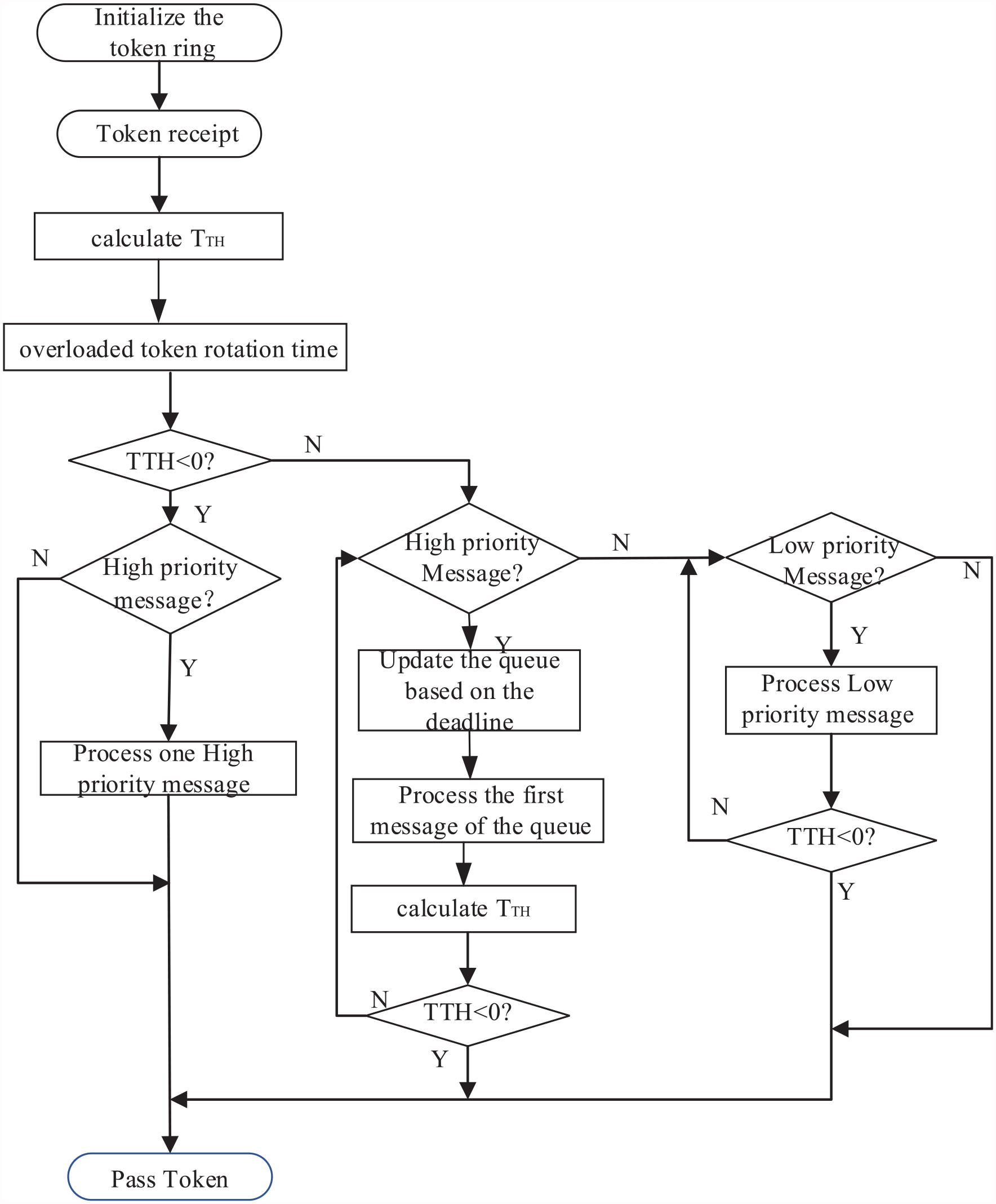
Flowchart of data transfer mechanism of PROFIBUS bus based on EDF scheduling algorithm.
PROFIBUS token ring single-cycle data transmission simulation data table.
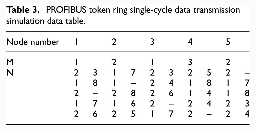
The number of master stations is 5, the first column of values in N represents the cycle of message transmission of each node, and the second column of values in N represents the deadline of low-priority queues at each station in milliseconds. The “-” symbol indicates that the corresponding message has no deadline date, that is, the point is considered as non-real-time message information, and the transmission time is allowed to be much later than the message information with an absolute deadline date. In practical engineering applications, the message transmission cycle is always less than the deadline date. If the message transmission cycle is greater than the absolute cut-off date, the message transmission error will occur and the transmission cannot be completed. The static scheduling algorithm under MAC is to carry out data response according to the frame command of random response. In simulation, the scheduling order of data transmission is simulated with the randomly generated message sequence. In the EDF scheduling algorithm, the transmission rule is determined according to the size of the deadline, and the transmission with a small absolute deadline is the first.
Based on the EDF scheduling algorithm, when the target token cycle time = 20, the real-time performance and transmission efficiency are calculated after polling for 10 cycles. The bus transmission efficiency based on the two scheduling algorithms is plotted in Figure 11.
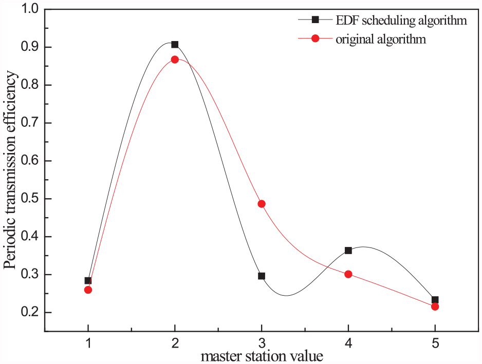
Comparison diagram of transmission efficiency of two different scheduling algorithms.
According to the simulation results and the random packet transmission cycle (about 40 ms) combined with the target token cycle time (20 ms) ratio, it can be concluded that the simulation results under the load factor is equal to about 200%, the two curves in the figure of the contrast trend can be seen that under the condition of the load factor is bigger, the transmission efficiency of the two basic consistent.
In order to better analyze the advantages and disadvantages of the EDF scheduling algorithm and the traditional scheduling algorithm, the load rate was changed for several experiments to observe the success rate of message transmission. In order to visually see the performance, the comparison results were plotted in Figure 12.
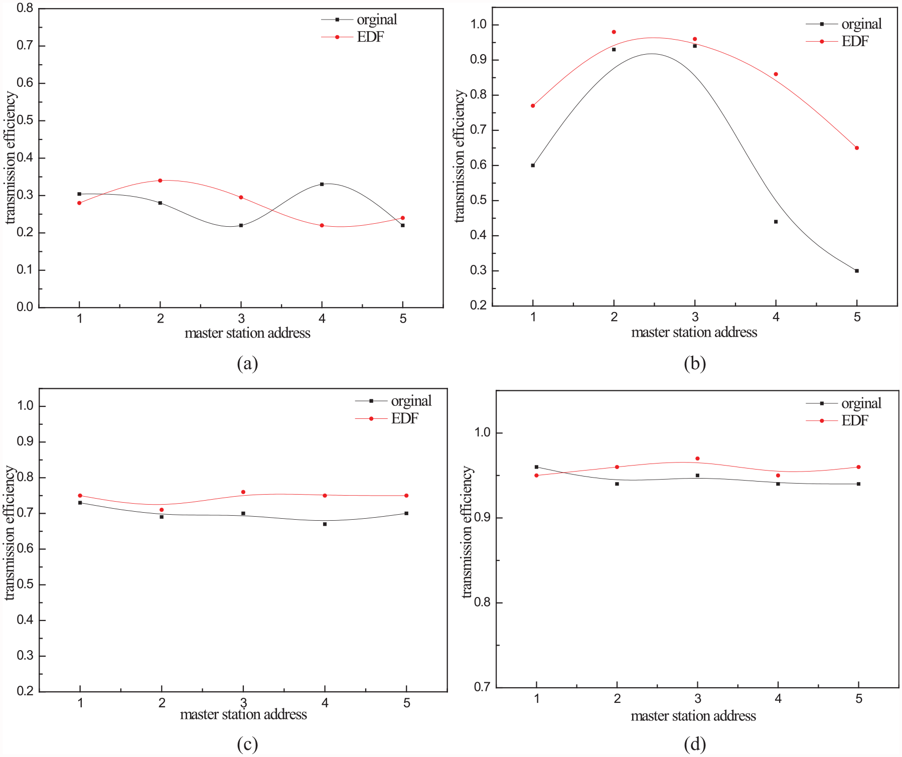
Comparison diagram of transmission efficiency of two different scheduling algorithms (a) TTR = 30, load factor = 130% (b) TTR = 45, load factor = 90% (c) TTR = 55, load factor = 72% (d) TTR = 65, load factor = 50%.
As it can be seen from Figure 12, when the load rate is small, it is reflected in the target token cycle time setting; that is, the target token cycle time setting is relatively large, which is large enough to complete all message transmission, and the bus transmission efficiency of EDF scheduling algorithm is basically consistent with the original scheduling algorithm, as shown in Figure 12 (d). When the load is moderate, that is, the target token cycle time can complete partial low-priority message transmission, the EDF scheduling algorithm has a better transmission rate than the original scheduling algorithm, as shown in Figures 12 (b) and (c). When the load rate is large, the target token cycle time is small and only a few low-priority messages can be transmitted, as shown in Figure 12 (a). At this point, the transmission efficiency of the two is similar, but the EDF scheduling algorithm can ensure the transmission of messages with strong real-time performance, so that the success rate of message transmission is improved to some extent.
Conclusion
In the field bus industrial control system, there is an important bridge between the management layer and the application layer. As a field bus with broad application background, the communication performance of PROFIBUS is the core evaluation index when it is applied.
The communication mechanism of bus is the most basic research objective of the bus. This article studies the communication performance of PROFIBUS fieldbus from both vertical and horizontal perspectives. The research model used intelligent programming software to analyze its transmission mechanism to get rid of the hardware redundancy of the traditional devices. The single-master slave station and multi-master slave station were modeled and the indexes were analyzed. The experimental results provide theoretical support for engineering practice.
Footnotes
Declaration of conflicting interests
The author(s) declared no potential conflicts of interest with respect to the research, authorship, and/or publication of this article.
Funding
The author(s) received no financial support for the research, authorship, and/or publication of this article.