
Abstract
The voltage sag problem in a power grid can be solved by a voltage regulator. In this study, the voltage regulator based on thyristor was used to compensate the single-phase and three-phase voltage of voltage sag fault, so as to recover the normal level of voltage. The simulation analysis was carried out on MATLAB. The results showed that voltage sag faults mainly affected the amplitude of voltage, but not the frequency of voltage. After voltage regulation, the single-phase and three-phase voltage waveforms in the fault period had a certain recovery, but the voltage regulator had a certain hysteresis effect.
Keywords
Introduction
The problem of power quality 1 can be summed up as the problem of voltage, current, and frequency which will make the user unable to use electricity normally or cause the electrical equipment to fail. Generally speaking, the duration of power quality problems is relatively short, and the impact will not be obvious to ordinary users. However, for some industries that require high power stability, even a short period of power quality problems may cause huge losses. Voltage sag 2 is one of the power quality problems with high frequency. Although the voltage sag does not change the frequency of alternating current (AC), it will reduce the voltage of AC. Once the voltage is lower than the rated voltage of the equipment, the equipment will stop working, resulting in a huge loss in production. In order to reduce the influence of voltage sag on a power grid, a voltage-regulating device is essential. The voltage regulator based on thyristor 3 can effectively solve the problem of static voltage and power quality. Zad et al. 4 proposed a direct voltage sensitivity analysis method based on network topology and independent of network operation point. By optimizing the reactive power of distributed generator sets, the system voltage could return to the allowable range. The optimal solution was obtained by implementing particle swarm optimization algorithm. The simulation results showed that the proposed algorithm could keep the system voltage within the allowable range. Yalçın 5 proposed a power flow model based on thyristor-controlled series compensator and tested it on IEEE 57 bus test system. The result showed that this method was fast, effective, and reliable. Alabduljabbar et al. 6 discussed a design and implementation of thyristor-controlled reactor based on static VAR compensator (SVC) system, in order to improve the voltage regulation ability and avoid voltage instability. They used Power Systems Computer-Aided Design (PSCAD)/Electromagnetic Transients including DC (EMTDC) software to simulate electric power system on remote areas of the kingdom of Saudi Arabia, and the results showed that in the similar case of installing network in extremely weak local distribution, the method was effective. The thyristor voltage-regulating system used in this study can regulate the voltage in single-phase, two-phase and three-phase AC. Single-phase AC means that there is only one winding in the AC generator, two-phase AC means that there are two orthogonal windings in the generator, and three-phase AC means that there are three windings in the generator. Since the 21st century, the two-phase electricity has been completely replaced by three-phase electricity, which is basically no longer used in the industry. Therefore, the AC voltage regulation in this study mainly focused on single-phase and three-phase electricity. In this study, the voltage-regulating function of the thyristor voltage-regulating system in single-phase and three-phase AC was simulated and analyzed using MATLAB software. Then, the actual test of the thyristor voltage-regulating system was carried out in the self-built single-phase and three-phase AC circuit models, and it was compared with another chopping-control voltage-regulating system.
Thyristor single-phase AC voltage–regulating circuit
As shown in Figure 1, the single-phase AC voltage–regulating circuit is mainly composed of a thyristor and two loaded electronic components, of which VT1 and VT2 are two thyristors. In practical applications, the load can be related to electrical appliances or inductors for transformers. Thyristor, also known as Silicon Controlled Rectifier (SCR), plays an important role in AC voltage–regulating circuit. It is divided into anode, gate, and cathode by P-N-P-N four-layer semiconductor. The characteristic of thyristor is that when positive voltage is applied to both anode and gate, the thyristor is in the conduction state as long as the positive voltage is not stopped after the conduction. In addition, the positive pulse voltage received by the gate must at least make the anode current meet the minimum standard. 7
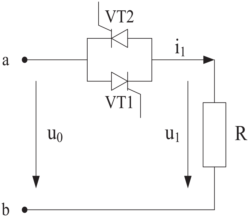
Single-phase AC voltage–regulating circuit.
In Figure 1, a and b points are connected to the AC voltage,
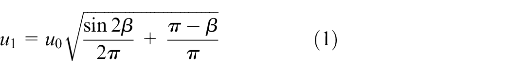
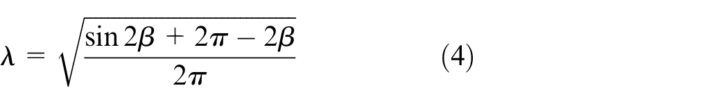
where
Thyristor three-phase AC voltage–regulating circuit
Three-phase AC voltage controller is shown in Figure 2. Starting from the zero crossing point of phase voltage, the trigger angles of thyristor VT1–VT6 differ by
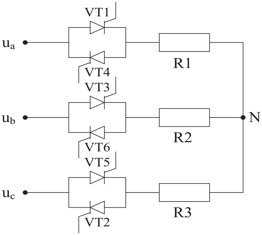
Three-phase AC voltage–regulating circuit.
Simulation experiment
Experiment setting
The experiment was carried out on the lab server, which was configured as Windows7 system, i7 processor, and 16 GB memory. Simulation software MATLAB was used. 11
In this study, MATLAB software was used to simulate the AC voltage–regulating system based on thyristor, and its main modeling is shown in Figure 3. The function of single-phase voltage module is to generate single-phase AC; the function of virtual three-phase system module is to convert single-phase AC into three-phase AC; the function of voltage detection module is to detect the voltage of single-phase AC generated by single-phase voltage module or three-phase AC generated by virtual three-phase system module, and the detection principle of this module is to decompose the input AC into DC component after abc-dq abc-dq transformation and low-pass filter and then calculating the voltage; the function of voltage comparison module is to compare the effective AC voltage obtained by voltage detection module with the preset AC voltage; and the function of trigger driver module is to send out pulse signal after receiving the corresponding signal, so as to activate the thyristor in the main circuit. There are two signals activated by the trigger driver module, which are the voltage deviation signal given by the voltage comparison module and the signal given by the zero crossing detection module. The function of the zero crossing detection module is to detect the voltage at both ends of the thyristor group in the main circuit module, so as to ensure the phase consistency when the thyristor compensates the sag voltage. The main circuit module is the core module of the whole AC voltage regulation system, and it is composed of six bidirectional thyristor groups. Its function is to turn on the thyristor immediately after receiving the pulse signal from the trigger drive module and to compensate the AC voltage through the series transformer.
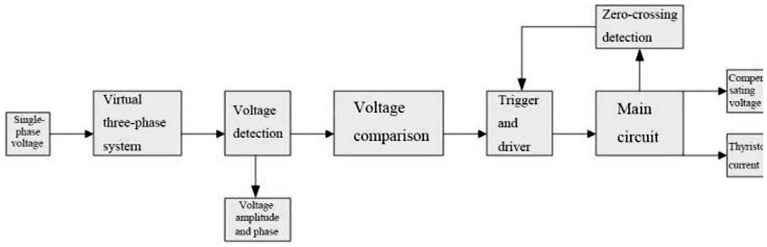
Simulation model of AC voltage–regulating system based on thyristor.
Simulation parameters
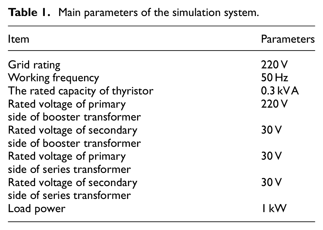
The main parameter settings of the AC voltage–regulating system in MATLAB simulation software are shown in Table 1. The rated working voltage of the circuit was set as 220 V, the AC working frequency as 50 Hz, the transformation ratios of the booster transformer and series transformer used for voltage compensation of the sag voltage in the main circuit were set as 22:3 and 1:1, respectively; the rated voltages of the primary and secondary side were as follows—booster transformer: 220 and 30 V and series transformer: 30 and 30 V. The load power on the working circuit was 1000 W. The voltage regulation range of thyristor was 0%–5%.
Main parameters of the simulation system.
Simulation program
The simulation system model was connected with single-phase AC with rated voltage of 220 V and connected with resistive load. Voltage sag was generated by single-phase AC within a certain period of time, and the voltage amplitude was set as decreasing from 311 to 280 V for a duration of 0.4 s. Both voltage waveform before adjustment and voltage waveform after adjustment were tested. The experiment was repeated for three times.
The simulation system model was connected with a 220-V rated three-phase AC and connected with the resistive load. The three-phase AC was set to generate a symmetrical voltage sag within a certain period of time, and the voltage amplitude was set as decreasing from 311 to 280 V for a duration of 0.4 s. Both voltage waveform before adjustment and voltage waveform after adjustment were tested. The experiment was repeated for three times.
Model experiment
In addition to the above simulation experiments, a small single- and three-phase AC voltage regulation experimental circuit model was also built. The model was composed of single- and three-phase generators, voltage regulation devices, lights as loads, and wires. The single-phase and three-phase generators could output single-phase or three-phase AC according to the demand, and the maximum voltage they could provide was 310 V; the voltage adjusting device could adjust the output voltage of the generator, which was used to simulate the short-term voltage mutation in the experiment; the light, as the load in the experiment circuit, had a working frequency of 50 Hz, a working power of 100 W, and a working voltage of 200 V.
In the thyristor voltage-regulating experiment, the thyristor AC voltage–regulating system was installed between the load light and the connecting circuit of the generator. The effective working voltage of the load light, 200 V, was input in the thyristor AC voltage–regulating system, and then the generator was started to detect the voltage and current at both ends of the load light. After the thyristor voltage-regulating system stabilized, the voltage according to the set effective working voltage, the voltage sag within a certain period of time was set using the voltage adjusting device: the voltage reduced by 2.5% within 0.4 s. The voltage waveform before and after the adjustment was detected. The experiment of the generator outputting single-phase AC was repeated for three times, and the experiment of outputting three-phase AC was also repeated for three times.
In order to understand the effect of the thyristor on the AC voltage regulation, it was compared with the chopping AC voltage regulation circuit (pulse width modulation (PWM)). PWM realizes the adjustment of alternating voltage based on the duty ratio of regulating switch (i.e. the conduction time of a switch in a switch cycle). In the comparative experiment taking PWM as the thyristor, the PWM voltage regulation system was installed between the load light and generator. In the PWM voltage regulation system, the effective working voltage of the load light, 200 V, was input, then the generator was started, and the voltage and current at both ends of the load light were detected. After the PWM voltage regulation system stabilized the voltage according to the set effective working voltage, the voltage sag within a certain period of time was set using the voltage adjusting device: the voltage reduced by 2.5% within 0.4 s. The voltage waveform before and after the adjustment was detected. The experiment of the generator outputting single-phase AC was repeated for three times, and the experiment of outputting three-phase AC was also repeated for three times.
Simulation results
Single-phase AC voltage adjustment results
Limited by the length of paper, only one experiment of voltage waveform was displayed. As shown in Figure 4, after voltage sag fault was generated by single-phase AC, the amplitude of single-phase alternating voltage between 0.1 and 0.5 s decreased obviously, from 311 to 280 V. Comparing the waveform frequency before and after voltage sag, it was found that there was no change. That is to say, fault only changed the voltage amplitude of voltage sag, but had no effect on the frequency.
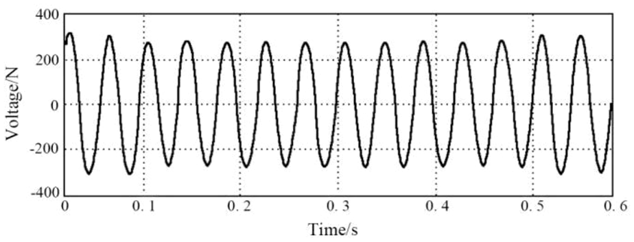
Detection waveform before single-phase AC voltage regulation.
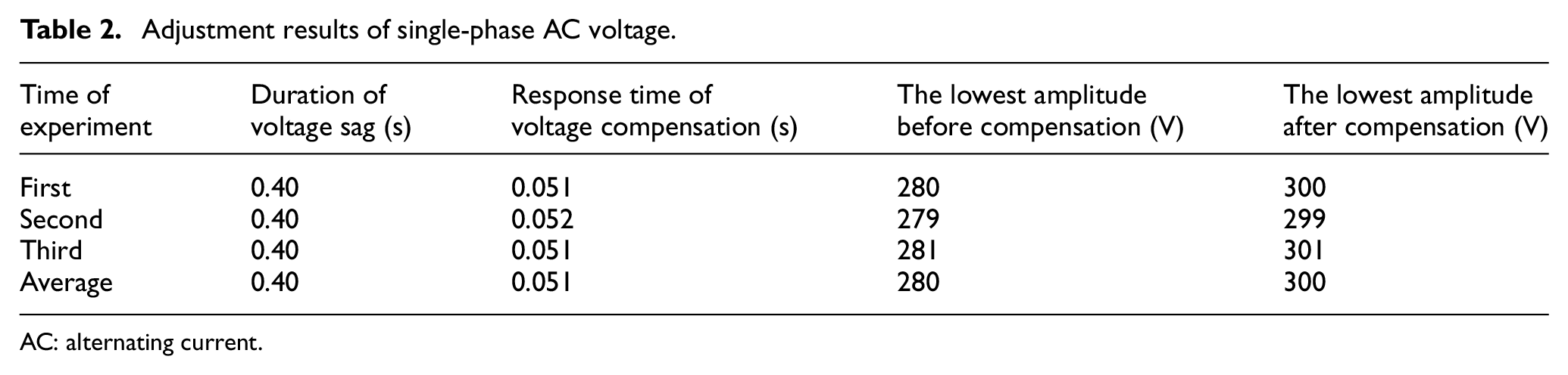
Limited by the length of paper, only one experiment of voltage waveform was displayed. As shown in Figure 5, compared with the waveform before voltage regulation in Figure 5, the voltage sag between 0.1 and 0.5 s after voltage regulation was compensated to a large extent and returned to the level before the fault. The changes of voltage amplitude in Figure 6 showed that the thyristor had a compensation effect on voltage sag. However, the compensation of thyristor voltage regulator for voltage sag was not perfect. It was seen from the changes of single-phase voltage amplitude in Figure 6 that the starting time of voltage sag fault was 0.1 s, in which the amplitude of single-phase AC voltage between 0.1 and 0.15 s did not immediately return to the original 311 V, but between 280 and 311 V, and then reached 311 V after about 0.15 s; at 0.5 s, the voltage sag fault ended, but the amplitude of single-phase AC voltage did not maintain the previous normal level. The amplitude increased to 320 V between 0.5 and 0.55 s and returned to the normal level after 0.55 s. Table 2 shows the results of three experiments of single-phase AC voltage regulation, in which the duration of voltage sag was a preset parameter, so it was 0.4 s; the response time of voltage compensation referred to the time from the moment of voltage sag to returning to normal level, and the average response time of three experiments was 0.051 s; the average minimum amplitude of voltage before compensation in the three experiments was 280 V, and the average minimum amplitude of voltage after compensation was 300 V.
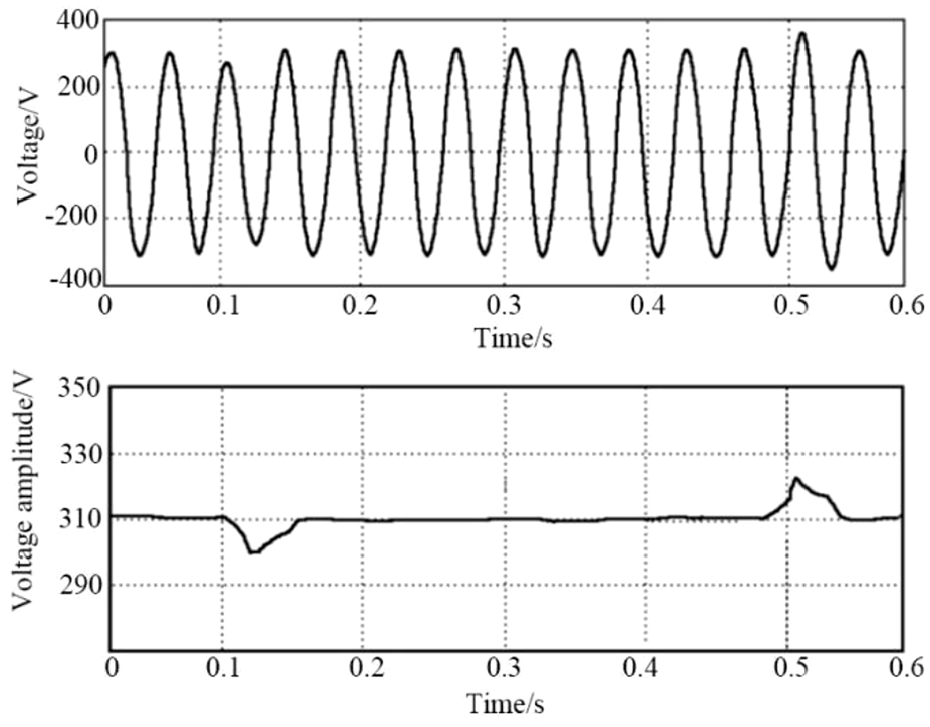
Detection waveform after single-phase AC voltage regulation.
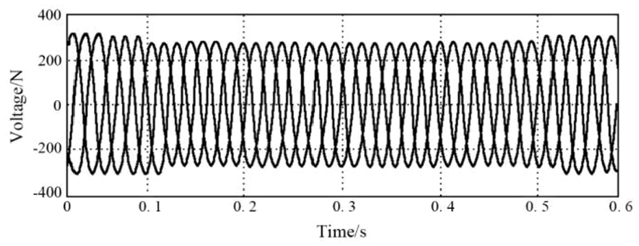
Detection waveform before three-phase AC voltage regulation.
Adjustment results of single-phase AC voltage.
AC: alternating current.
Three-phase AC voltage adjustment results
Limited by the length of paper, only one experiment of voltage waveform was displayed. As shown in Figure 6, the phase difference between the voltages of each phase in the three-phase AC voltage was
As shown in Figure 7, compared with the waveform before voltage regulation in Figure 6, the voltage sag between 0.1 and 0.5 s of waveform after voltage regulation was compensated to a large extent and basically returned to the level before the fault. Moreover, as the voltage sag was set as symmetrical in this experiment, the change of voltage amplitude only showed one of them. The change of voltage amplitude showed that thyristor had compensation effect on the three-phase voltage sag. However, the amplitude of the three-phase AC voltage between 0.1 and 0.18 s at the beginning of the voltage sag fault did not immediately return to the original 311 V, but between 280 and 311 V, and reached 311 V after 0.18 s. At 0.5 s, the voltage sag fault ended, but the amplitude of three-phase AC voltage did not maintain the previous normal level. The amplitude increased to 320 V between 0.5 and 0.59 s and returned to the normal level after 0.59 s. Table 3 shows the results of three experiments of single-phase AC voltage regulation, in which the voltage sag duration was the set value, so it was 0.4 s; the average voltage compensation response time of three experiments was 0.081 s; the minimum amplitude of the average voltage before compensation was 280 V; and the minimum amplitude of the average voltage after compensation was 300 V.
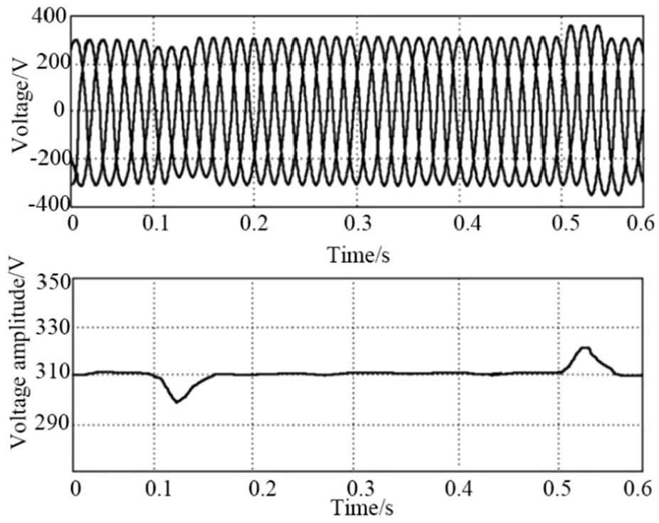
Detection waveform after three-phase AC voltage regulation.
Adjustment results of three-phase AC voltage.
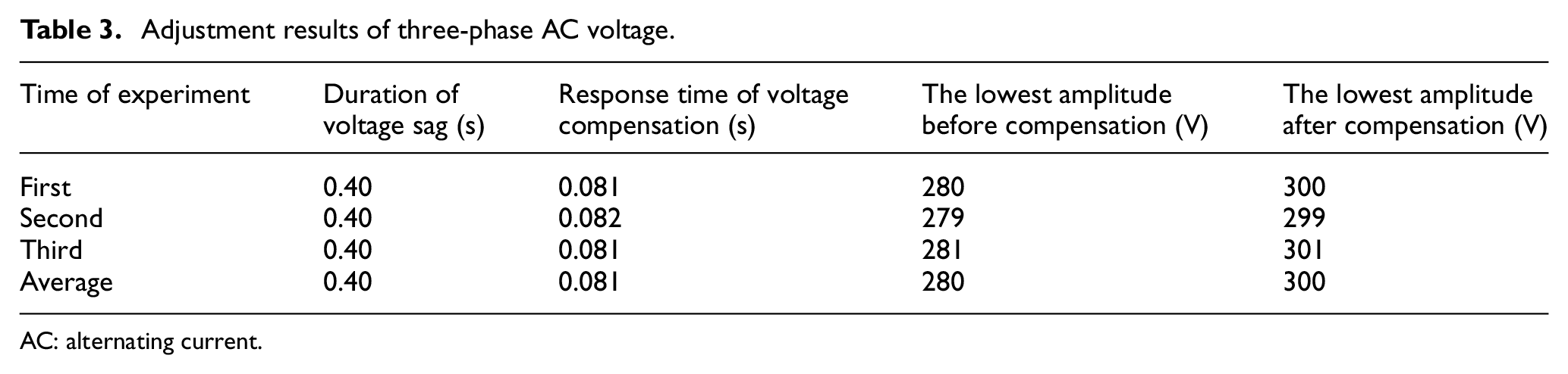
AC: alternating current.
Model experiment results
In the single-phase and three-phase AC model experiments, the change trend of voltage waveform detected at both ends of the load light under the two AC voltage regulation methods was basically consistent with the simulation experiment. The average results of the three experiments are shown in Table 4. In the single-phase AC thyristor voltage regulation experiment, the duration of voltage sag was 0.40 s, the compensation response time was 0.51 s, and the voltage before and after compensation was 195 and 200 V, respectively. In the three-phase AC thyristor voltage regulation experiment, the duration of voltage sag was 0.40 s, the compensation response time was 0.81 s, the voltage before and after compensation was 195 and 200 V, respectively. In the single-phase AC PWM voltage regulation experiment, the duration of voltage sag was 0.40 s, the compensation response time was 0.72 s, and the voltage before and after compensation was 195 and 199 V, respectively. In the single-phase AC PWM voltage regulation experiment, the duration of voltage sag was 0.40 s, the compensation response time was 0.91 s, and the voltage before and after compensation was 195 and 199 V, respectively. It was seen from the comparison in Table 4 that the response time of the thyristor after detecting the voltage sag was significantly shorter than that of PWM, that is, the thyristor could make compensation for the voltage sag faster so that the voltage could be kept stable as much as possible. Moreover, the compensation of the thyristor for the sag voltage was more sufficient, and the voltage after PWM compensation has not yet fully recovered to the original voltage.
Average results of single and three-phase AC model experiments under two AC voltage regulation methods.
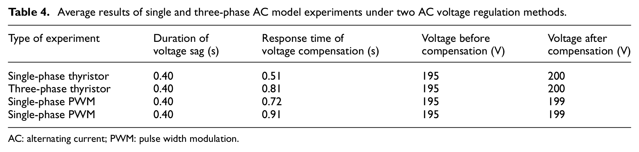
AC: alternating current; PWM: pulse width modulation.
As mentioned above, under the two AC voltage regulation methods, the change trend of the voltage waveform was very similar to the result in the simulation experiment. But differing from the smooth voltage curve in the simulation experiment, the actual voltage curve detected in the model experiment was not a smooth curve, but had noise and harmonic distortion. After Fourier transform of the voltage curve, it was found that the fifth and seventh harmonics contained high harmonic components, as shown in Table 5. It is seen from Table 5 that the fifth harmonic component was smaller than the seventh harmonic component after AC voltage regulation with thyristor, and the fifth harmonic component was larger than the seventh harmonic component after AC voltage regulation with PWM. Moreover, in terms of total harmonic distortion, the single-phase AC and three-phase AC which adopted thyristor for voltage adjustment had smaller total harmonic distortion, that is, using thyristor for voltage regulation could make AC voltage distortion smaller.
Average results of harmonic in single and three-phase AC model experiments under two AC voltage regulation methods.
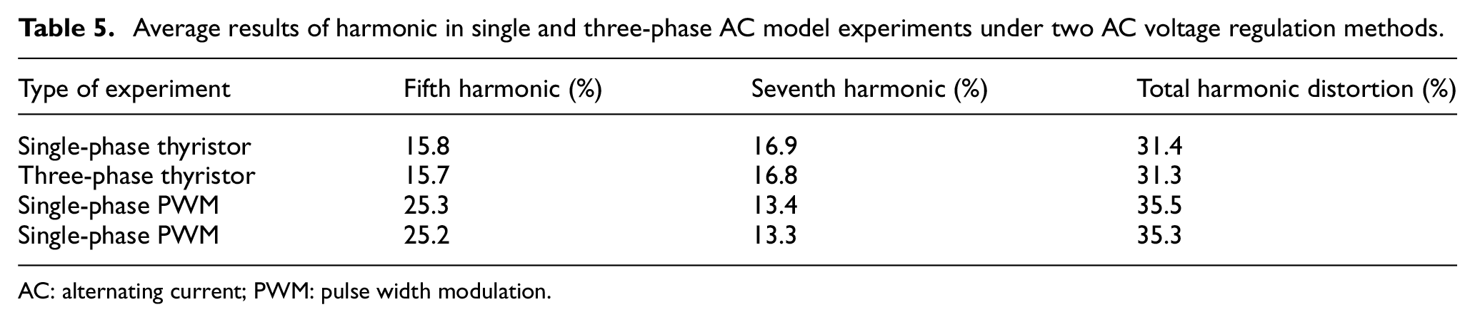
AC: alternating current; PWM: pulse width modulation.
Discussion
In modern daily life, electric power has become an indispensable part. The stable supply of electric power is closely related to the quality of life and work. At the same time, the improvement of production level makes the power demand more and more, which makes the scale of power grid increase gradually, and the probability of power grid system failure also increases, among which voltage sag is one of them. Voltage sag 12 is a short-term or long-term phenomenon of power supply voltage reduction caused by grid circuit fault. For general electrical appliances, short-term or long-term voltage sags have little or no obvious impact, but for instruments with very sensitive working voltage, a short-term voltage sag may cause damage to the instrument. Therefore, it is very important to reduce the influence of voltage sag on power supply stability. 13
In this study, the thyristor was used to regulate the AC voltage to reduce the impact of voltage sag on the power grid. After that, the method was tested on MATLAB software with single-phase and three-phase AC voltage as the subjects. The simulation results of single-phase AC voltage and three-phase AC voltage showed that the thyristor could effectively compensate the AC voltage of voltage sag, but there was a certain degree of delay when compensating the two types of AC voltage, that is, when the voltage sag occurs, although the AC voltage–regulating circuit detected it, the thyristor did not immediately compensate the voltage, and there was a delay. Finally, the voltage was compensated to be stable as a whole, but there was still sag in a short time. The reasons for the above phenomena are as follows: (1) in order to avoid the distortion and harmonics when the thyristor compensated the voltage, the voltage zero crossing detection technology was used to control the conduction of the thyristor, and the information of the zero crossing detection needed some time to be fed back to the thyristor, so it was inevitable that there was a certain degree of lag and (2) in actual application, the thyristor will adjust in real time according to the voltage deviation. The opening and closing of the whole different thyristor group will cause a short circuit in the process of switching the circuit. In this study, the bypass transition switching was used to avoid the short circuit phenomenon, and this process needed some time to meet the zero crossing detection, resulting in a certain lag in the actual voltage compensation.
The comparison of the results of single-phase and three-phase AC voltage regulation found that the lowest amplitude before and after voltage compensation was basically the same when the fault time of voltage sag was the same, which showed that the compensation effect of thyristor to single-phase and three-phase AC voltage was not much different, but compared with the compensation response time of both to voltage sag, it was found that the response time of thyristor to the single-phase AC voltage was shorter. The reason may be that when the thyristor adjusted the three-phase voltage, it compensated each phase voltage separately; the different phase of the three-phase voltage made the time point of the zero crossing detection of the thyristor different, and the compensation response time of the whole increased after the superposition of them.
Later, in the model comparison experiment between the thyristor voltage-regulating system and the chopping voltage-regulating system, the experimental results showed that the change trend of voltage waveform in the fault of voltage sag was close to that in the simulation experiment. Under the two voltage-regulating systems, the voltage-regulating system based on the thyristor had faster response and more sufficient compensation to the voltage sag. The innovation of the voltage-regulating system based on thyristor adopted in this study compared with the chopping voltage-regulating system is that the thyristor is used for voltage regulation. Thyristor which is a contactless switch plays the role of tap switch in the whole voltage-regulating device, while the switch which plays the role of tap switch in the chopping voltage-regulating system is a solid switch with touch spot. Thus, the thyristor-based voltage-regulating system can respond to the voltage fault faster, and the tap changing is more frequent and fast.
Conclusion
This study briefly introduced the working principle of thyristor single-phase voltage-regulating circuit and thyristor three-phase voltage-regulating circuit and then built a simulation model of the AC voltage–regulating system based on the thyristor on MATLAB simulation software and conducted voltage-regulating simulation for single-phase and three-phase AC voltages with voltage sag fault. The results showed that (1) the amplitude of single-phase and three-phase AC voltages decreased from 311 to 280 V within 0.1–0.5 s of the voltage sag fault, but the frequency did not change and (2) when compensating the single-phase and two-phase voltage with using thyristor, the compensation effect was almost the same, but the compensation response time for power sag was shorter, the average response time of the single-phase voltage was 0.051 s, and that of the three-phase voltage was 0.081 s. In this study, the thyristor was used to compensate the voltage sag in the power grid, and the compensation effect of this method on the single-phase and three-phase voltage was tested in the MATLAB simulation experiment, which provides an effective reference for the voltage compensation technology. The shortcoming of this study is that AC which is processed by voltage regulation has harmonic in the practical application because of the non-linear characteristic of different devices, though thyristor can play a good role in the simulation experiment. Therefore, the future research direction is to reduce the response time when the thyristor compensates the three-phase voltage as much as possible and reduce the influence of harmonic on AC.
Footnotes
Declaration of conflicting interests
The author(s) declared no potential conflicts of interest with respect to the research, authorship, and/or publication of this article.
Funding
The author(s) received no financial support for the research, authorship, and/or publication of this article.