
Abstract
At present, open-loop synchronous control for hydraulic systems widely using synchronous valves has low synchronous accuracy due to weak anti-bias capacity, and is hard to adjust synchronization velocity, so it could not meet the requirements of accurate synchronization under severe conditions. In this paper, a load-sensing synchronous control is developed to obtain accurate synchronization in open-loop control, which is made up of a load-sensing unit and a synchronous valve. In the load-sensing loop, a load-sensing pump supplies pressure and flow required by the system through pressure closed-loop control, and a load-sensing valve could improve the capability of anti-offset loads by pressure compensation. The synchronous valve is between the load-sensing pump and load-sensing valve, to achieve equal distribution of flow supplied by the pump, which could improve the divider accuracy of the load-sensing system. A test system within load-sensing synchronous control is established, and then comparison experiments under different partial loads are carried out. The experimental results show that, compared with the traditional synchronous valve control, the load-sensing synchronous control has the advantages of higher synchronous precision, higher energy efficiency and also the ability of velocity regulation. Load-sensing synchronous control has the potential of high precision synchronization control in server environments.
Introduction
Synchronization drive1,2 refers to two or more actuators driving a load at the same speed. Compared with mechanical and electrical synchronous drive, hydraulic synchronous drive3,4 has the advantages of large output force, compact structure and suitable for high-power applications. It is widely used in aerospace drive devices 5 and construction machineries, 6 in which double-cylinder synchronous drive is the main form.
There are two kinds of control forms for synchronization drive: closed-loop control and open-loop control. Some closed-loop control methods in hydraulic systems are developed, such as backstepping control,7–9 robust adaptive control,10–12 unknown dynamics estimator control,13,14 and achieve very high control precision by feedback and dynamics estimation. However, closed-loop control for hydraulic system is very complex and costly, at least including servo valves or proportional valves, controller, various sensors, and is not suitable for severe environment (e.g. mine) due to its complexity. The open-loop control for hydraulic synchronization mainly uses throttling valves, 15 synchronous valves16,17 and synchronous motors, 18 and is very simple and reliable, so it is suitable to very poor working condition. However, compared with closed-loop control, the accuracy in open-loop synchronization control is low. For example, synchronous deviation using throttling valves, synchronous valves and synchronous motors is generally more than 10%, 5% and 1%, respectively. Although using synchronous motors could obtain relatively high accuracy, synchronous motors are expensive, 19 and synchronous valves are wildly applied to hydraulic synchronization because of low cost. Moreover, the above synchronous systems in open-loop control use a constant pressure oil source, which would lead to large heat and low efficiency due to the overflow loss and pressure loss, and the synchronous velocity is hardly adjusted in process. Overall, existing open-loop synchronous control has some serious drawbacks, such as low accuracy, low efficiency, and the difficulty of velocity regulation.
In order to overcome above shortcomings of open-loop synchronous control, we propose a new synchronous control scheme, load-sensing synchronous control (LSSC) and explain its structure and principle in detail, and then establish a test system to test its synchronous performances, and the comparison experimental results verify the new control scheme.
System design and principle of LSSC
The hydraulic principle diagram of LSSC system is shown in Figure 1, where two cylinders are driven synchronously. The LSSC system consists of a LS pump, a LS valve, a synchronous valve. The LS pump supplies pressure and flow according to load demand by pressure closed-loop control, which could improve the system efficiency;20,21 the LS valve is used to regulate the velocity of actuators by adjusting its opening. It is important to emphasize that its two sections’ opening should remain the same, and there is a pressure compensator in LS valve,22,23 which could enhance the capability of anti-offset load of actuators; the synchronous valve has the function of flow equalization and is connected in series between the LS pump and LS valve to equally distribute the flow supplied by the pump. The synchronous valve establishes the dynamic relationship between two load-sensing branches, which can improve the synchronization accuracy.
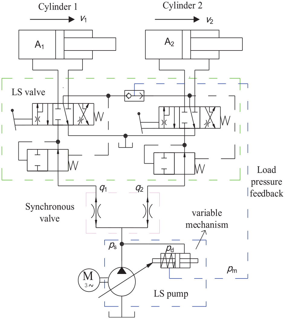
Hydraulic principle diagram of system under LSSC.
This control scheme integrates the advantages of synchronous valve control (SVC) and load-sensitive control, and has following advantages: strong anti-bias ability under open-loop control, high synchronization accuracy, high efficiency and the capacity of velocity regulation. So LSSC especially adapts to the harsh conditions where closed-loop control could not be available.
System molding under steady state
This section will describe the pressure and flow rate of the system and the speed of actuators under steady state. There is a pressure balance equation of LS pump at steady state, that is

where
The flow rate of LS pump is

where
If ignoring the system leakage, the pump output flow is divided by the synchronous valve, and there is a flow balance equation in the LSSC system, that is
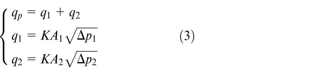
where
The velocity of two actuators is given by
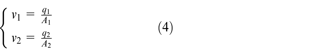
where
Test system
In order to verify the synchronous characteristics of LSSC, a test system is established. Figure 2 shows its hydraulic principle diagram, and Figure 3 is the test rig. The test system includes a driving unit and a loading unit, where two driving cylinders in LSSC drive two loading cylinders, and the cylinder stroke is measured by draw-wire encoders. The loading pump supplies oil for the loading unit, and the back pressure of loading cylinders is controlled by two proportional relief valves (PRV), and setting different overflow pressures could realize offset loads. The maximum pressure difference is set to 4 MPa, corresponding to load difference of 61544 N, which is a heavy partial load for a cylinder with 140 mm diameter.
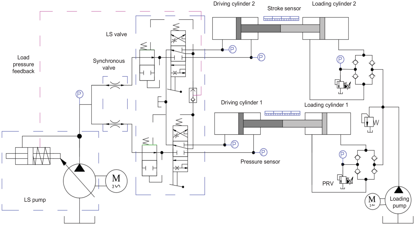
Hydraulic principle diagram of test system under LSSC.
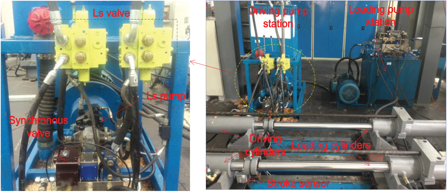
Test rig of LSSC.
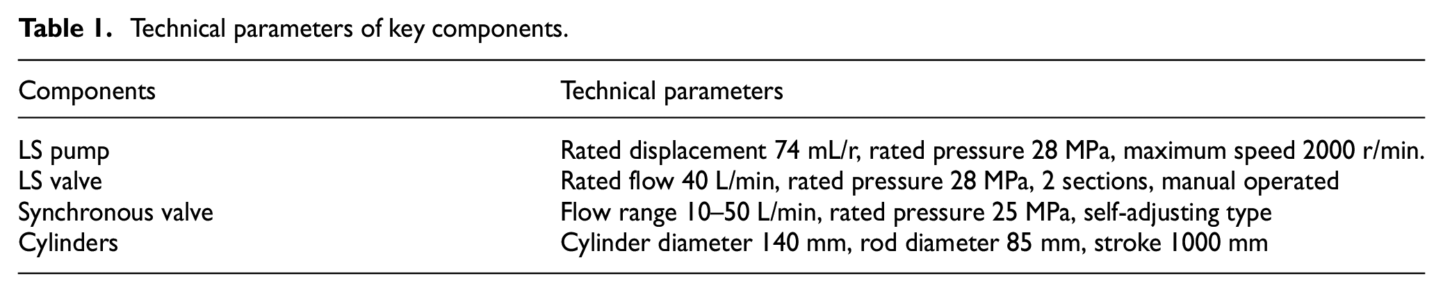
The parameters of main hydraulic elements are listed in Table 1. The rated pressure is 25 MPa, and rated flow rate is 100 L/min, the cylinder stroke is 1000 mm. The test system in LSSC could switch to SVC by retaining synchronous valve and the removing the LS valves and replacing the LS pump by a fixed pump. To verify the synchronization characteristics of LSSC, we make a detail comparison between LSSC and SVC.
Technical parameters of key components.
Experiments and analysis
Synchronous performances under partial loads
First, synchronous driving in LSSC and SVC under different partial loads is carried out. Experimental results under the partial loads of 2 and 4 MPa are shown in Figures 4 and 5, respectively. The comparison of synchronous errors under LSSC and SVC is listed in Table 2, where synchronous deviation e is expressed as follows
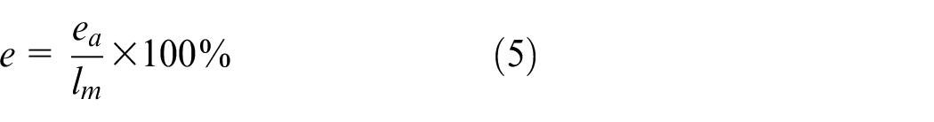
where
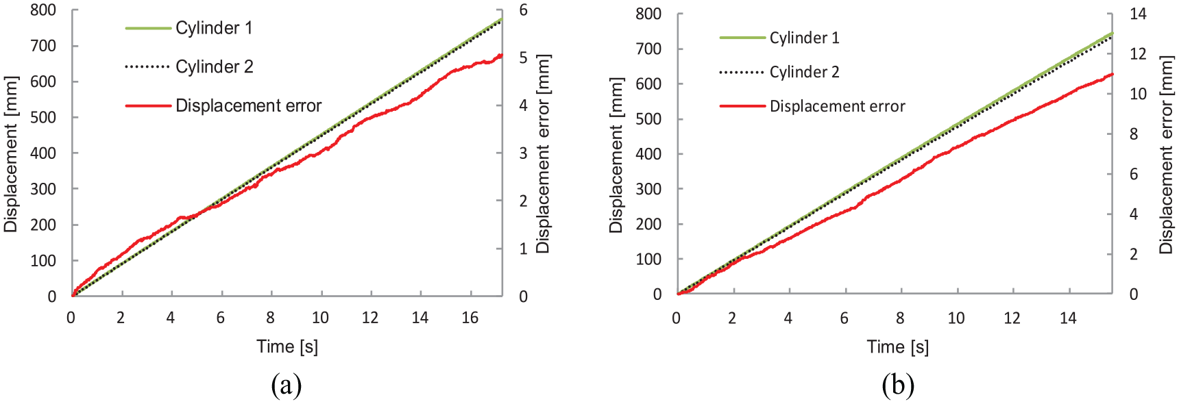
Synchronous displacement and error under the offset load of 2 MPa: (a) under LSSC; (b) under SVC.
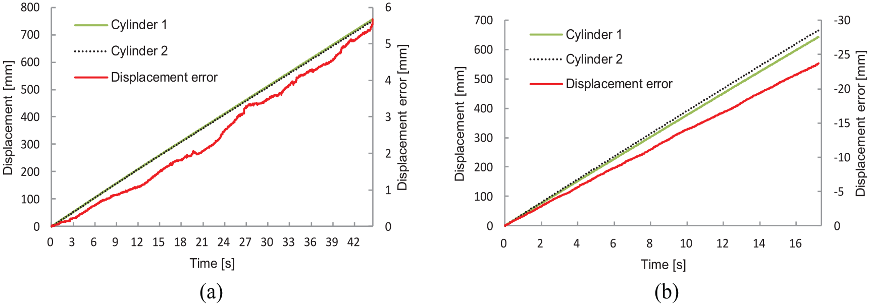
Synchronous displacement and error under the offset load of 4 MPa: (a) under LSSC; (b) under SVC.
Synchronous error in LSSC and SVC under different offset loads.
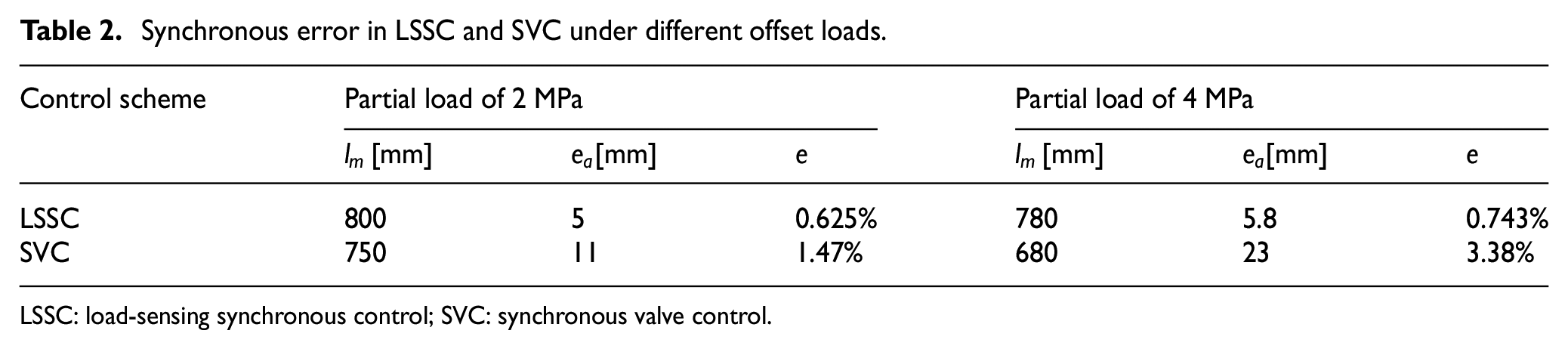
LSSC: load-sensing synchronous control; SVC: synchronous valve control.
Experimental results show that, for both LSSC and SVC, larger offset load will lead larger synchronous deviation; compared with SVC, LSSC has higher synchronous accuracy under partial loads, and its deviation is less than 1%, because LSSC has stronger ability to resist partial loads due to the pressure compensation function of LS valves.
System performance
Next, the system efficiency comparison between LSSC and SVC is made. The test is carried out under the same working conditions with the same load and the same velocity. Figures 6 and 7 show the system flow and pressures at the pushing stage and pulling stage under the offset load of 4 MPa, and the synchronous velocity is set to 20 mm/s and 30 mm/s at pushing stage and pulling stage, respectively. Table 3 and Table 4 show the system flow and pressures under LSSC and SVC at pushing stage and pulling stage, respectively.
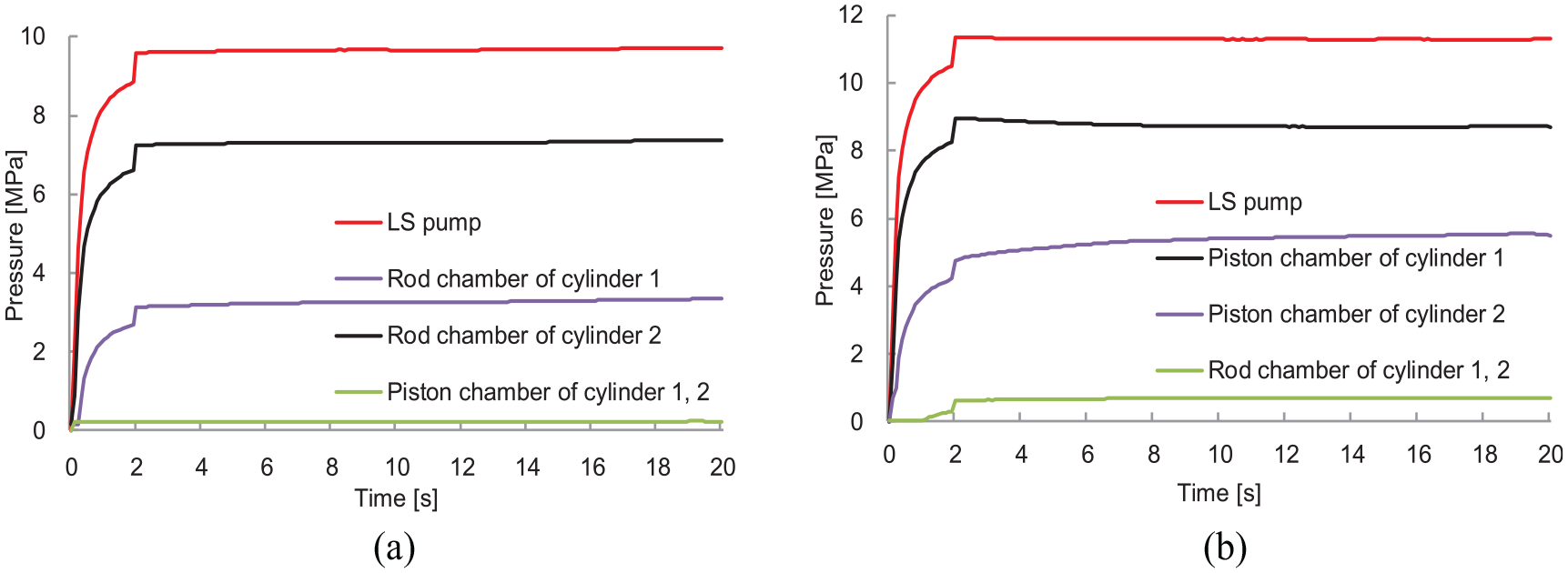
System pressures under LSSC and SVC at pushing stage: (a) under LSSC; (b) under SVC.
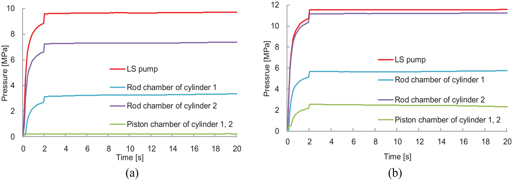
System pressures under LSSC and SVC at pulling stage: (a) under LSSC; (b) under SVC.
System flow and pressures under LSSC and SVC at pushing stage.
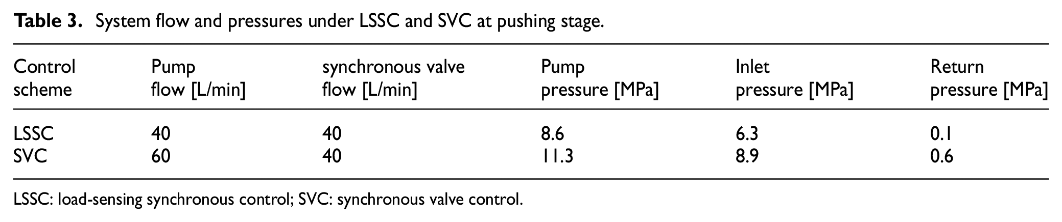
LSSC: load-sensing synchronous control; SVC: synchronous valve control.
System flow and pressures under LSSC and SVC at pulling stage.
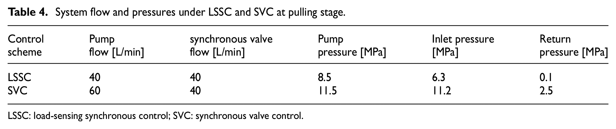
LSSC: load-sensing synchronous control; SVC: synchronous valve control.
Test results indicate that compared with the SVC system, the LSSC system is characteristic of high efficiency. Reasons are following. First, the control scheme of SVC uses a fixed pump to supply oil, the pump pressure is set by a relief valve and cannot vary with loads, and the pump outputs a large amount of flow much more than the system demands, which results in a great deal of overflow loss. However, the control scheme of LSSC could realize system pressures and flow consistent with the load demand by load-sensing technology, which avoids overflow loss and excessive pressure loss. Second, when the driving cylinder returns back, under the SVC scheme the synchronous valve is in the flow collecting state and results in large fluid resistance and return pressure, but under the LSSC scheme the synchronous valve is still in the flow dividing state, and the return oil of driving cylinder passes through the LS valve to tank with very little back pressure. Therefore, at the pulling stage, the return pressure under LSSC is much smaller than that under SVC, which can further reduce energy lose.
In order to test the efficiency of the system more directly, we have carried out the temperature rise experiment. Normally, the temperature rise could directly reflect the efficiency level of a hydraulic system, and the lower the temperature rise, the higher the system efficiency. Figure 8 shows the oil temperature rise of system in LSSC and SVC under the same working conditions. Within 35 minutes, the oil temperature under SVC rose from 32°C to 55°C, a total of 22°C. However, the oil temperature under LSSC only rose 3°C within the same time. Therefore, the result further proves that the synchronous system in SVC is with high heating and low efficiency, and the synchronous system in LSSC has the advantage of higher efficiency with less heating.
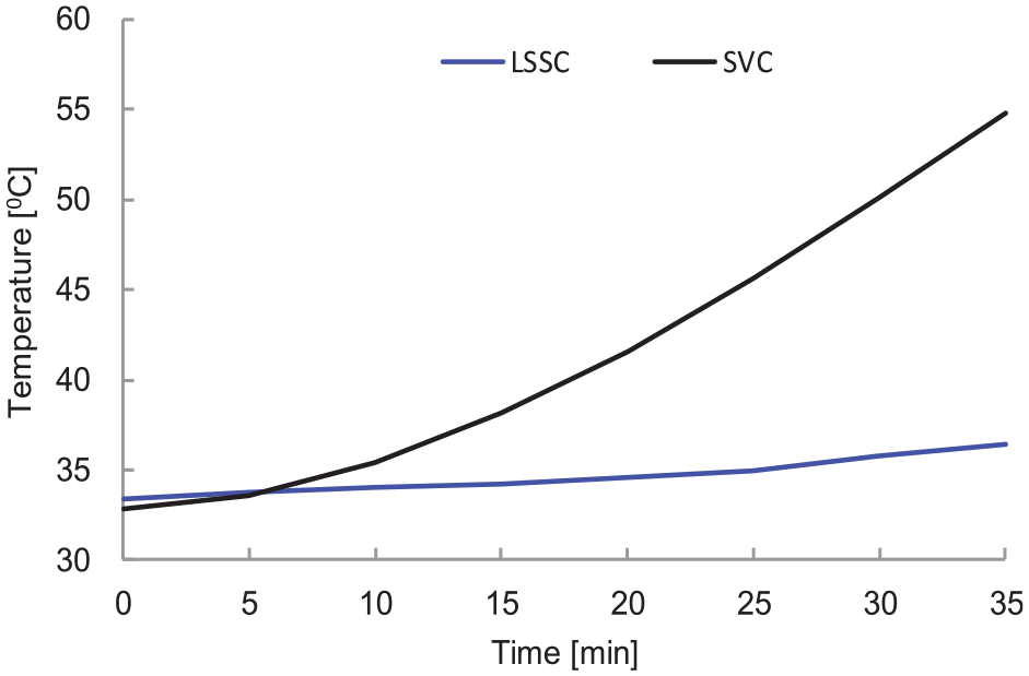
Temperature rise of system under LSSC and SVC.
Synchronous performances in variable velocity
Finally, the variable velocity synchronous experiment under LSSC is carried out by adjusting opening of LS valves. Figure 9 shows variable velocity synchronization under the offset load of 4 MPa. Experimental results indicate that using LSSC could achieve variable velocity synchronization of multi-actuators; the synchronous accuracy is still high, but is lower than that in constant velocity situation, that is because the synchronous valve cannot adjust dynamically with the flow rate in time. The variable velocity function will enhance the stability of synchronous motion.
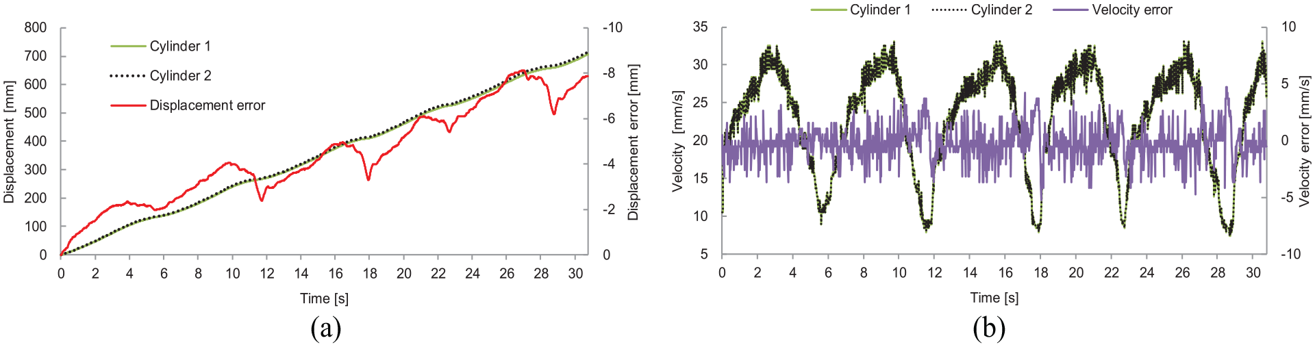
Variable velocity synchronization under LSSC: (a) displacement and synchronous error; (b) velocity and synchronous error.
Conclusion
To obtain high-precision synchronization in open-loop control, a new synchronization scheme LSSC is proposed, which integrates the advantages of SVC and load-sensitive control. Comparative experimental results indicate that compared with traditional SVC scheme, the new scheme has the following advantages:
LSSC scheme has the advantage of higher synchronization accuracy with stronger capability of anti-bias loads.
LSSC scheme has the advantage of higher efficiency with less heating, because LSSC can realize the system pressure and flow meet the load demand by load-sensing control in LS pump, which will avoid overflow loss and reduce pressure loss.
LSSC scheme has the function of variable velocity synchronization, and the actuators velocity could be regulated by adjusting the opening of LS valve, and the function will enhance the stability of synchronous motion.
Footnotes
Declaration of conflicting interests
The author(s) declared no potential conflicts of interest with respect to the research, authorship, and/or publication of this article.
Funding
The author(s) disclosed receipt of the following financial support for the research, authorship, and/or publication of this article: This work is supported by a Project Funded by the Priority Academic Program Development of Jiangsu Higher Education Institutions and the Fundamental Research Funds for the Central Universities (2019XKQYMS37). Many thanks also go to the editors and reviewers for their helpful comments.