
Abstract
In present research work, an attempt has been made on the development of titanium carbide–reinforced magnesium-based surface composites through friction stir processing technique. Particularly, attempt has been made to observe the influence of input processing conditions, namely tools-pin geometry, travel speed, and rotational speed for the mechanical importance (surface hardness and elastic modulus) of the developed composites. Further, the, incurred modifications in the metallurgical characteristics and corrosion behaviour of the developed composites have also been analysed through microscopic and scanning electron microscopy, and immersion fluid test, respectively. It has been found that the quality characteristics of the composites have been greatly influenced by the selected range of input variables. As noticed, the grain size of the magnesium alloy has been significantly reduced from 22.42 to 6.6 µm. Furthermore, the maximum level of the micro-hardness (180 HV0.3) of the processed composite with square-shaped tool-pin geometry. Moreover, the degradation rate of the processed composite is found to be 45% lesser than the unprocessed magnesium alloy.
Introduction
Friction stir processing (FSP), originally derived from well-known friction stir welding (FSW), is a novel processing route proposed by Mishra et al. 1 in late 20th century for imparting desirable modifications in the metallurgical characteristics of the materials which can result in better mechanical, corrosion, thermal, electrical, and wear properties.2–4 Being a solid-state processing method, FSP includes no melting of materials during FSP that effectively avoids the formation of porous holes, pin holes, and thermal cracks. Along with this, FSP also helps to eliminate the dilution rate of the work-materials and improves the microstructure and properties of the base metal, significantly. 5 This method develops highly localized heat, as a result of a friction developed between a rotating tool, non-consumable, and the stationary work surface for creating deformation, plastically, beneath the tool. 6
The FSP can be implemented on a conventional FSW machine via a non-consumable rotating tool with a pin/shoulder of required cross-section. During FSP, the tool rotates at high speed and plunges into the workpiece under axial force until the shoulder contacts the surface of the workpiece leading to friction (Figure 1). 5 In stir-zone, plastic modifications have produced metallurgical wonders, for instance, disruptive build-up, retrieval, and finally dynamic recrystallization. 7 Furthermore, the stir-zone houses subordinate phases, such as fillers and reinforcements, that have been decisively supplemented to form composite.2,3
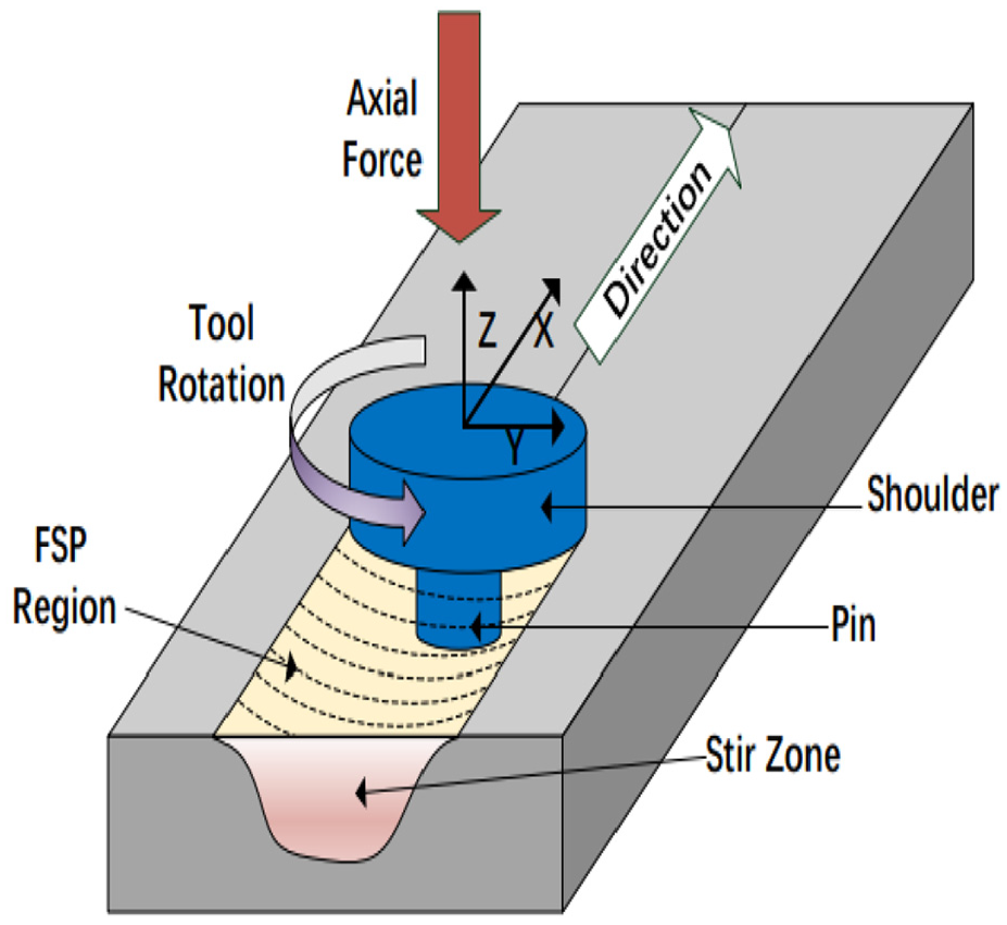
Schematic representation of FSP. 5
The material under goes thermo-mechanical action, and heat-affected zone was developed in FSP process, similar to FSW process. 8 Due to FSP, the grains of materials were recrystallized, and homogeneous fine equiaxed grains were formed. 9 The amount of high-angle grain boundaries in the processing region is increased after FSP 10 and promotes plasticity of the base metal. 11 Typically, onion-ring patterns can be seen in stir-zone owing to the flow of the plastic material layer from the front of the tool. 12 It has also been reported by the researchers that the process variables such as rotation speed of the tool, feed rate of the tool, tool-pin geometry, tilting angle, and penetration depth are found as the most significant parameters of FSP which usually affects the mechanical and metallurgical transformations happening in the processes zone.13–15
Primarily, the use of FSP is mainly explored for the surface treatments of aluminium-based alloys, with no noticeable challenge in the use of type of reinforcement.16–19 Indeed, magnesium (Mg) alloys have vast engineering submissions, especially for aerospace, 20 automobile, 21 and biomedical 22 as of their high strength/weight ratio, damping abilities, electrical/thermal conductance, and ease of recyclability. 23 However, Mg alloys are suffering from various drawbacks which majorly include ductility and, indeed, it has the tendency of enhancement through FSP through recrystallization, grain refinement, and introduction of the reinforcements.18–20 Moreover, the different types of alloys processed through FSP has shown enhanced levels of the mechanical, 21 tribological, 22 corrosion resistance, 23 and biocompatible properties. 24 It has been observed in the literature that, the suitability of a broad variety of filling media including titanium carbide (TiC), alumina (Al2O3), silicon carbide (SiC), boron carbide (B4C), tungsten carbide (WC), fly ash, and different types of Mg composites could be fabricated.25,26 Table 1 shows the practical implications of the FSP-based Mg composites.
Illustration of FSP-based Mg composites for practical utility.
FSP: friction stir processing; MWCNTs: multi-walled carbon nanotubes.
It has been found that the tool-pin geometry has a great scope for producing desirable changes in the characteristics of the work material.35,36 Therefore, different types of tool-pin geometries contributes in different prospective in order to improve the quality of the friction stir processed (FSPed) composite and pure specimens. The tensile strength of the microstructural transition regions in as-FSPed samples was found to be equivalent/lower than as-received parental material. The mechanical features of the processed material decreased by increasing the distance from the FSPed zones. 36 Furthermore, the key observations made in the literature are (1) the percentage of reinforcement considered also has a strong influence on the mechanical properties of the composite surface, 37 increasing the transverse speed has increased the grain size, 38 and after the incorporation of nano-sized ceramic fillers in Mg alloy, the mechanical performance of the alloy has been enhanced. 39 However, there is a huge scope for the in-depth investigation of the FSPed Mg composites to study the influence process factors. 40
From the available literature, it has been observed that no research study available on the synthesis of nano-TiC-reinforced Mg-Y-Zr-RE alloy. In this study, an attempt has been made to develop WE43/TiC composites using nano-sized TiC reinforcement and to study the influence of tool-pin geometries (cylindrical, square, and triangular), travel speeds, and rotational speeds on the micro-hardness and elastic modulus of the as-fabricated composites. Metallurgical and corrosion properties of the FSPed WE43/TiC samples have also been investigated to establish the process parametric measurable performances’ correlations.
Materials and methods
Materials and FSP
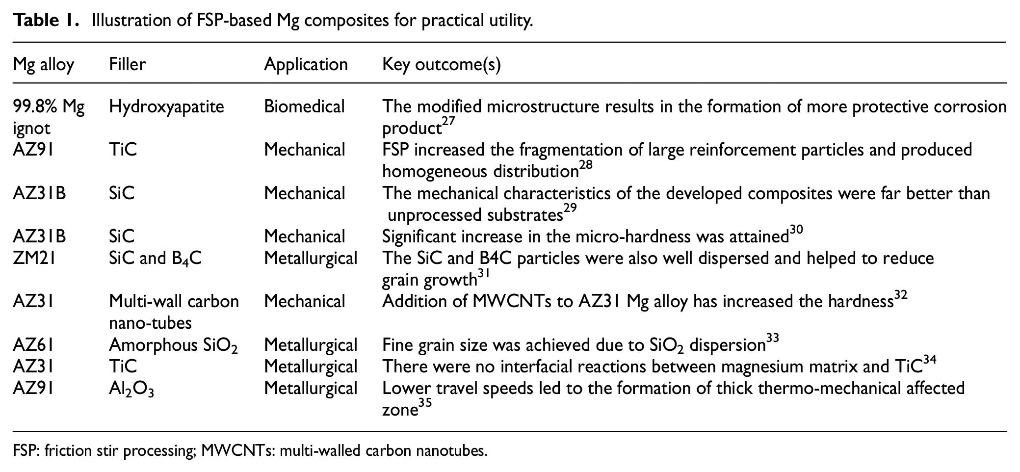
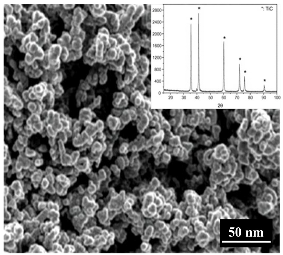
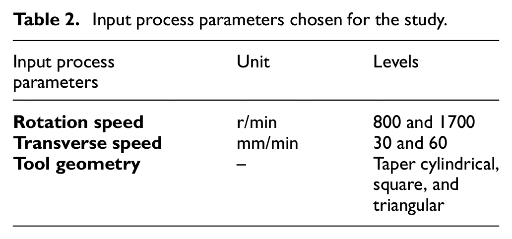
WE43 Mg alloy (Mg-Y-Zr-RE) was used as a substrate for FSP. Table 1 shows the elemental composition of WE43 Mg alloy. The specimens of 100 mm × 50 mm × 6 mm size were cut from the rolled sheet for FSP process. For surface processing, nano-sized silicon carbide (TiC) of particle size <5 nm, procured from Intelligent Materials Private Limited, Dera-Bassi (India), has been used as the reinforcements, as can be seen in Figure 2, and X-ray powder diffraction (XRD) pattern of nano-sized TiC powder confirms the purity level. Figure 3 shows the in-house developed FSP process by modifying the vertical milling machine. Before FSP, the holes of dimension Φ1.5 mm and depth 2 mm were drilled on the WE43 substrate at an interval of 8 mm along the line of processing as can be seen in Figure 4. The nano-sized SiC powder was filled into these holes. After filling powder in the holes, in order to prevent sputtering or ejection of filler reinforcements, the holes were covered with a friction tool without a pin. After that, FSP was carried out on the covered surface plate specimens using different geometries such as taper cylindrical, square, and triangular with shoulder diameter of 20 mm. Hardened H13-tool steel (hardened to 65 HRC) was chosen as tool material. Table 2 present the input process parameters chosen for the research study. The pin dimensions were taken as ϕ-5 mm/h-4 mm for taper cylindrical. For triangular and square tools, the dimension of side is 5 mm × 5 mm, as can be seen in Figure 3 for better illustration. The tool tilt angle was kept 2° and set constant. The processing of the as-rolled plates has been carried out at different process parameters such as rotational speed (800 and 1700 r/min), transverse speeds (30 and 60 mm/min), and tool geometries (taper cylindrical, square, and triangular). The effect on process parameters on the mechanical properties (nano-hardness and elastic modulus) and microstructure was investigated.
Morphology and XRD pattern of nano-sized TiC powder.
Experimental setup of in-house modified vertical milling machine.
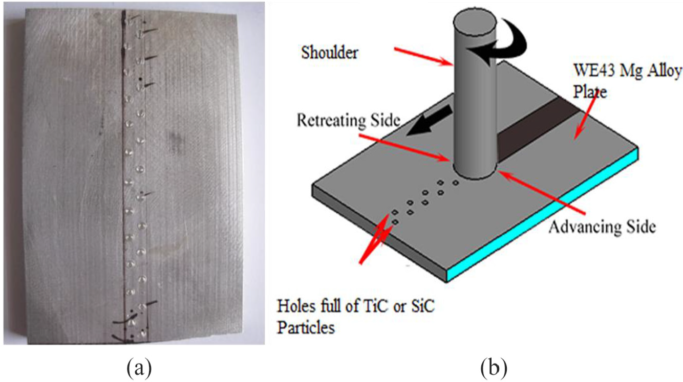
(a) Drilled hole (1.5 mm × 2 mm) of WE43 plate surface filled with nano-sized SiC powders and (b) schematic representation of surface possessing of WE43 Mg alloy using FSP process.
Input process parameters chosen for the study.
Characterization of microstructure and phase composition
For microstructure investigations, the samples were cut from the FSP zone in the size of 15 mm × 15 mm by low-speed diamond cutter and cleaned with ethanol. Then, the specimens were well polished using graded series in sequence (400, 800, 1500, and 2000) of emery paper, and then refined using diamond paste of 0.1 μm and, thereby, etched with 2% Nital solution. After that microstructure analysis has been performed with the help of optical microscopy and electron microscopy (field emission scanning electron microscopy (FE-SEM); JSM-7600F; JEOL, USA).
The elemental composition of WE-43 Mg alloy before and after FSP process was investigated by energy dispersive spectroscopy (EDS) coupled with FE-SEM. The detailed microstructure examination and grain size investigation was carried out electron backscatter diffraction (EBSD) map. The backscatter electron (BSE) detector was equipped with FE-SEM. The data of EBSD results were analysed by Orientation Imaging Microscopy, OIM analysis technique.
Mechanical properties
The modulus of elasticity as well as hardness of WE43/SiC composites were observed with the help of nano-indenter (Hyistron TI-950, Bruker’s, Minneapolis, USA) by employing Oliver–Pharr approach at 1000 μN. The observed nano-hardness of specimens was confirmed by testing the micro-hardness of specimens. The micro-hardness of the specimens was measured with Vickers micro hardness (HMV-G21ST, Japan) at an indentation load of 300 gm with dwell time of 15 s. Before indentation, the samples were polished using graded series in sequence (400, 800, 1500, and 2000) of emery paper and then polished with up to 0.1 μm diamond paste and napped cloth, as per the procedure reported in previous studies.41–44
Corrosion resistance
The corrosive potential of WE43 alloy prior and after FSP process was analysed in 3.5% wt. of NaCl solution using dynamic potential–based polarization sampling in an electrochemical system (Gamry Instruments, Warminster, USA). The WE43 alloy samples were treated as test electrode; graphite rode as counter electrode, and saturated carmol electrode (SCE) as reference electrode. The corrosion characteristics were measured using Tafel exploration method, as presented in previous studies following ASTM-G31-72 rule.44–50 In order to check the degradation rate, the samples were dipped in NaCl solution for 24, 48, and 72 h, respectively. Upon predetermining the time period, samples have been taken out of the solution and were weighed. Finally, the lost weight upon releasing Mg2+ in NaCl solution has been assumed as degradation rate.
Results and discussion
Microstructure evaluation
Figure 5 shows the scanning electron micrograph and EDS spectrum of unprocessed and FSPed WE43 alloy substrates. Unprocessed WE43 alloy exhibit plane morphology, only finishing marks can be seen, as shown in Figure 5(a) and (b). At higher magnification (2000×), grain boundaries WE43 Mg alloy can be seen, which confirm that surface is unprocessed, as can be seen in Figure 5(b). The associated EDS spectrum of WE43 alloy confirmed the presence of Mg, Y, Zr, and Nd elements, which confirmed the base elements of WE43 alloy. Figure 5(c) and (d) shows the morphology of nano-TiC-reinforced WE43 alloy. From the FE-SEM micrograph, it can be clearly seen that nano-TiC is uniformly distributed in the matrix of WE43 alloy after FSP process, but mostly nano-TiC were also observed in the nano range. The associated EDS spectrum of FSPed WE43 alloy confirmed the presence of Ti, C, O along with Mg, Y, Zr, and Nd elements. The peaks of Ti, C, and O elements confirmed and conferred the reinforcement and distribution of nano-TiC in the matrix of WE43 alloy. Furthermore, the transformation in the grain size of composites has also been determined through electron back scattered diffraction imaging (Figure 6). It has been established that FSP of WE43 alloy has significantly reduced the grain size of the selected alloy. The average grain size of the FSPed WE43 alloy has been recorded as 22.42 µm, whereas, the grain size after FSP of the same has reduced significantly to 6.6 µm, with square tool-pin geometry. This noticeable reduction in the grain size of the WE43 with FSP has a strong influence on the resulting mechanical properties of the alloy and, thereby, composites. This means that FSP technique is not only suitable for changing the chemical composition of the substrate, through reinforcement, but also to incur better surface morphology that can enable the substrates to sustain demanding engineering applications.
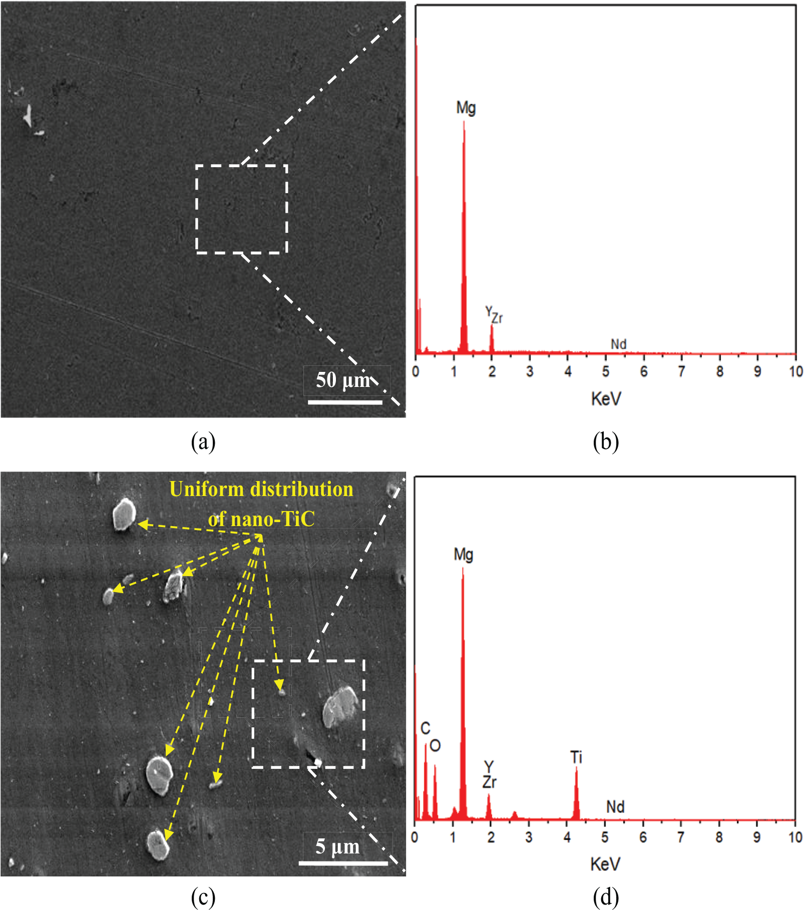
Morphology and associated EDS spectrum of with and without TiC-reinforced WE-43 composite after friction stir processing ((a) and (b)) unprocessed WE-43 and ((c) and (d)) TiC-reinforced WE-43.
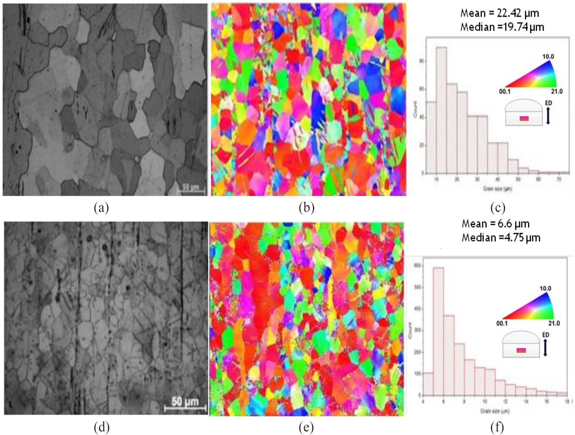
Microstructure, electron backscatter diffraction image, and grain size of WE43 alloy before ((a)–(c)) and after friction stir processing ((d)–(f)).
Effect of tool-pin geometry on surface morphology
The effect of tool-pin geometry on the distribution of nano-TiC was investigated. Figure 7 shows the SEM images of the processed WE43/TiC composites prepared with different type of tool-pin geometry. On comparing the micrographs, it has been noticed that with square pin geometry, highly uniform distribution of the nano-TiC particles has been obtained on the surface of WE43. Moreover, clusters of TiC particles have been formed on the modified surface. The distribution of the TiC particles has also been seen in case of triangular and cylindrical tool-pin geometries; however, the distribution of TiC is significantly less when compared with the cylindrical and triangular tool-pin geometries. This is because with square tool-pin geometry, very less TiC particles have been repelled by the tool out of the processing zone; hence, resulting in better distribution. With triangular pin geometry, few TiC clusters are visible on the processed zone which is sufficiently embedded in the WE43 alloy. Whereas, in case of the taper tool-pin geometry, no cluster formation has been seen.
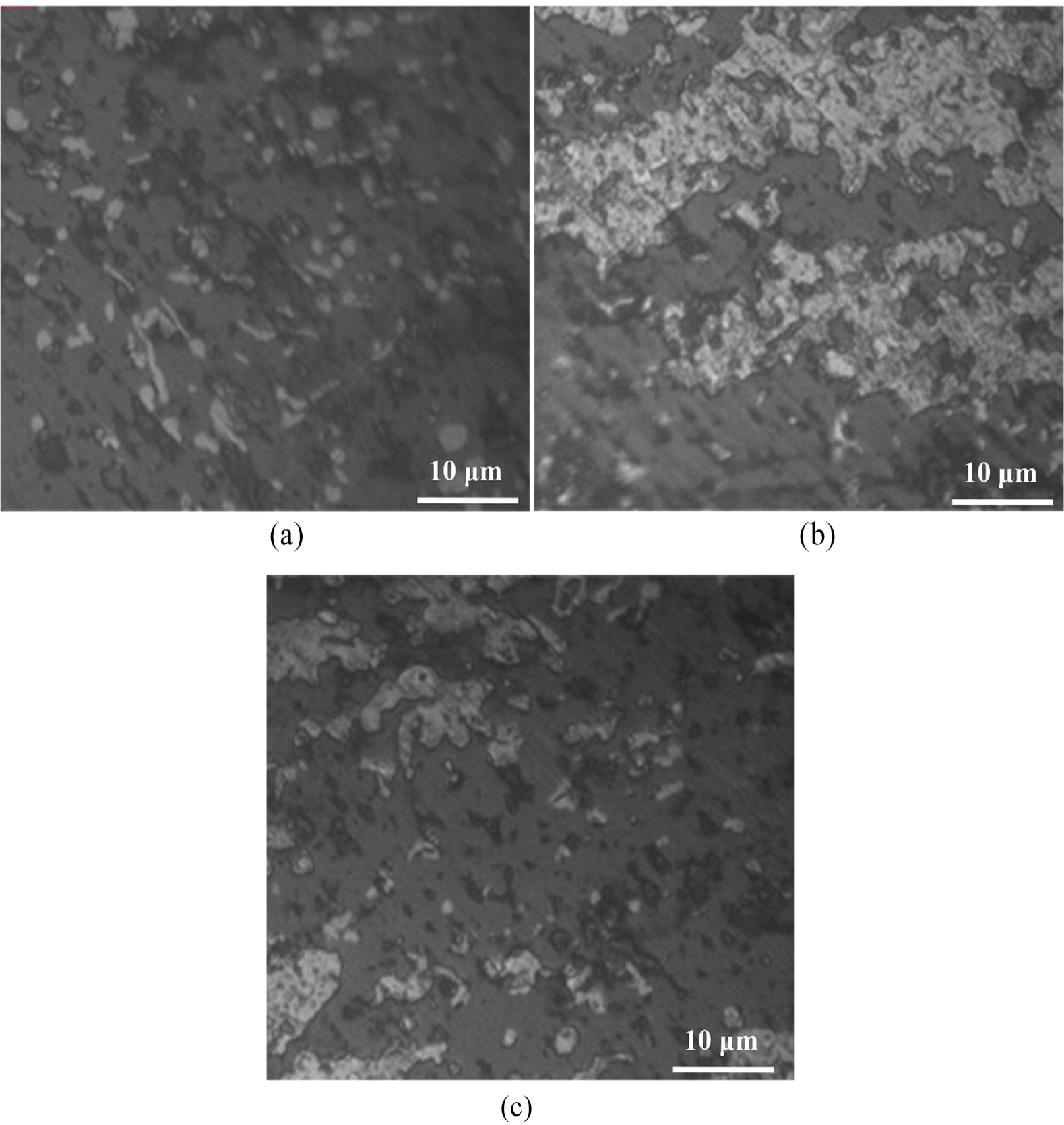
SEM images for WE43/TiC composites processed with taper cylindrical (a), square (b), and triangular (c) tool-pin geometries.
Mechanical properties
Micro-hardness and elastic modulus of the WE43/TiC composites was measured by nano-indentation graph. Figure 8 shows the load versus depth of indentation plot for WE43 alloy before and after FSP. It can be seen that the depth of penetration is less in WE43/TiC composites as compared with unprocessed WE43 composites, which confirmed that the micro-hardness of WE43/TiC composites is more than the unprocessed WE43 composites. Due to FSP process, the size of grain particles reduced, and the strength of composite increased, which resist the penetration. Hence, the observation also confirmed that the WE43/TiC composites possessed high elastic modulus than unprocessed WE43 alloy. The micro-hardness of the WE43/nano-TiC composites, processed through FSP method, has been recorded.
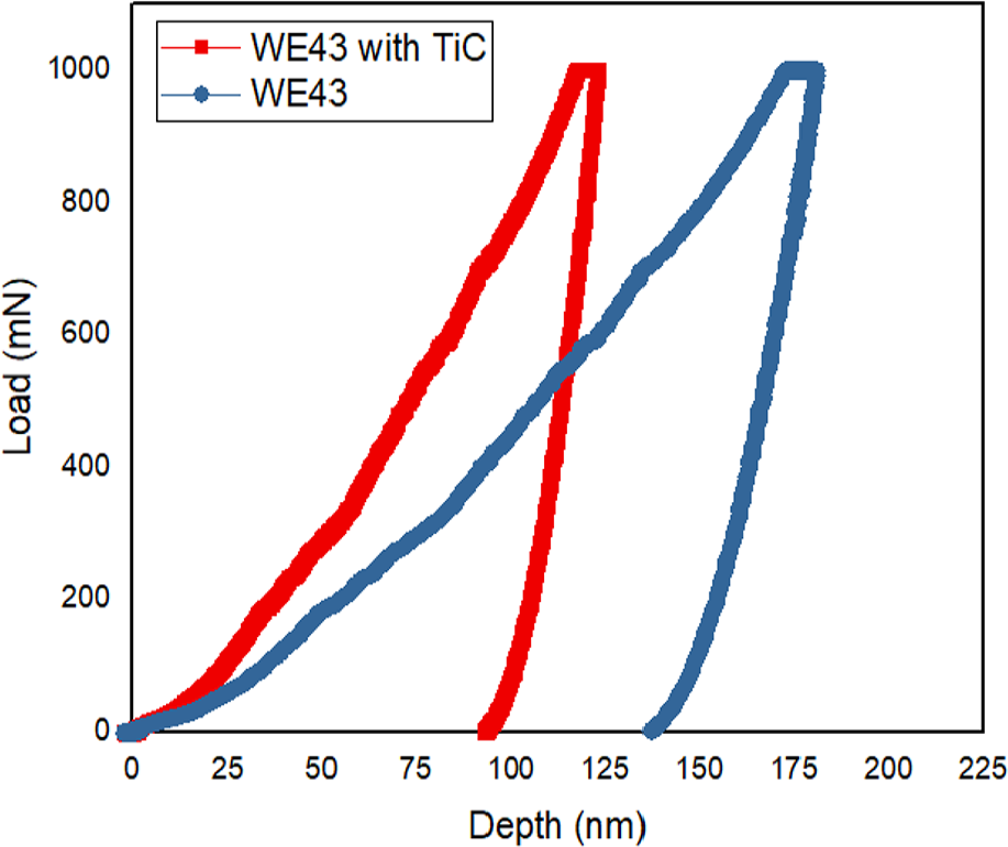
Load versus depth of indentation plot for WE43 alloy before and after friction stir processing.
Figure 9 shows the indented micrographs of unprocessed WE43 alloy and WE43/TiC composite. It has been found that the micro-hardness of the unprocessed WE43 alloy and WE43/TiC composite was 87 HV0.3 and 180 HV0.3, respectively.
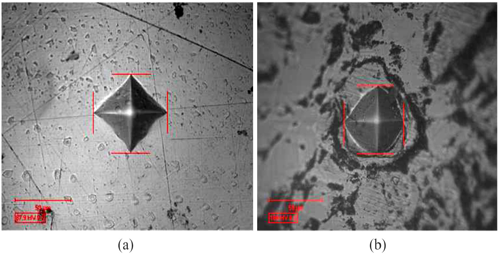
Micro-hardness of WE43 alloy before (a) and after friction stir processing (b).
Noticeably, the depth of indenter penetration has been affected by the presence of the reinforcement that has effectively contributed to the enhancement of the micro-hardness. Figure 10 shows the line plots for micro-hardness of the WE43/TiC composites prepared with different tool geometries. From this figure, it has been found that the maximum hardness of the prepared composites was obtained with square shape of the tool-pin geometry (185 HV0.3).
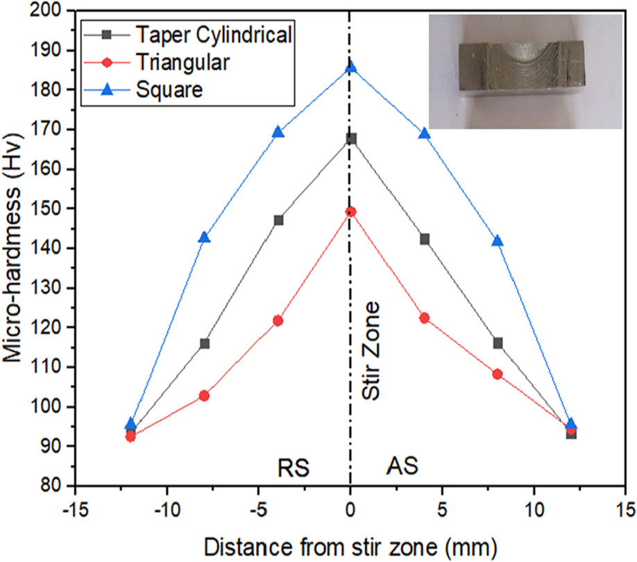
Line plots for micro-hardness of WE43/TiC composites using different tool geometries.
However, the triangular geometry of the tool also resulted in a comparatively similar value of the micro-hardness, ranging about 167 HV0.3. In case of taper tool-pin geometry, the obtained hardness value was observed as 146.5 HV0.3. As observed, the tool-pin geometry has an important role in the surface processing of the WE43 substrate and, therefore, in the mixing of the reinforcement. It has been found that in case of square tool-pin geometry, the FSP tool caused high material temperature in the processing zone and a thicker nugget, when compared to the taper tool-pin geometry. The thicker nuggets are the results of higher processing/recrystlization force. Similarly, cylindrical tool-pin geometry also resulted in thicker nuggets and a broader processing zone area. Indeed, the cylindrical and triangular tool pins obtained equal processed area and resulted in better surface processing and mixing of nano-TiC particles. However, in case of square pin geometry, it has been found that the processed zone was greater than triangular and cylindrical pin geometry. At 5 mm distance away from the centre of the processed zone, average of 170 HV0.3 hardness was produced, whereas in case of taper cylindrical and triangular pin geometry, the average hardness at 4 mm distance from weld line is 141.85 and 121.58 HV0.3, respectively. However, at 12 mm from the processed zone, the average micro-hardness of the processed WE43/TiC composites prepared with taper cylindrical, triangular, and square pin geometry is approximately 93.55 HV0.3. This is because, the measurement zone is away from the processed zone and the observed value of micro-hardness is equal to base materials. Overall, the best micro-hardness of the composites was obtained with square pin geometry. Figure 11 shows the influence of input parameters on micro-hardness and elastic modulus of the WE43/TiC composites. From Figure 11(a), it has been found that by increasing rotational speed from 800 to 1700 r/min, the micro-hardness and elastic modulus of the prepared specimens has increased. Generally, the rotational speed is related to the frictional force induced by the rotating tool in the work surface. Therefore, when the rotational speed was higher, large amount of heat has been produced. Owing to this, the thermal gradient developed by the processing surface was higher, which resulted in the higher heat transfer rate and therefore, has resulted in the small grain structure. Similarly, from Figure 11(b), it can be seen that the travel speed of the tool geometry is inversely proportional to the micro-hardness and elastic modulus. Basically, the travel speed in the FSP is the feed rate at which the tool passes over the work surface. As regards to the result obtained in this study, it has been found that the travel speed of the FSP tool has a great importance when concerned with the processing time spent by the tool-pin geometry on the work surface. The higher level of travel speed of the FSP tool has interrupted the complete processing of the work surface that did not produce the quality surface, as sufficient energy for the successful surface treatment has not accumulated. Thus, it influenced the obtained micro-hardness and elastic modulus of the work surface. Noticeably, at the travel speed of 30 mm/min, the obtained value of the micro-hardness is higher than the same produced at 60 mm/min. Similarly, in case of elastic modulus, it has been found that the value obtained at 30 mm/min is higher than the same produced at 60 mm/min. When it comes to tool-pin geometry, from Figure 11(c), it has been found that the highest level of micro-hardness has been obtained with square geometry, higher than triangular and cylindrical tool-pin geometry. The reason behind the resulted trends has been well discussed, previously. As regards to the elastic modulus of the processed composites, it has been found that the values obtained with square tool-pin geometry is higher than the elastic modulus obtained with triangular and cylindrical tool-pin geometries, respectively. Overall, for desirable results, tool-pin geometry, rotational speed, and transverse speed should be kept as square, 1700 r/min, and 30 mm/min, respectively.
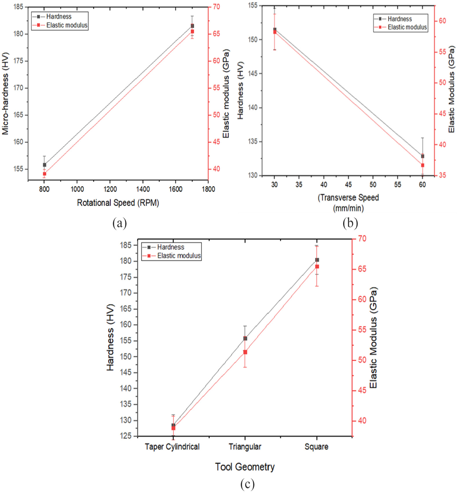
Effect of (a) rotational speed, (b) transverse speed, and (c) tool geometry on hardness and elastic modulus.
Effect of FSP on corrosion characteristics
The corrosion characteristics, resulting in the degradation of the WE43 alloy and WE43/TiC composite has been assessed with extrapolation method (Tafel) and immersion test. Figure 12(a) highlights the obtained corrosion results. It can be seen from the figure that the WE43/TiC composite possessed lesser resistance to the corrosion when compared with WE43 alloy. It can be noticed that the composite specimen sustained a higher magnitude of the current density and electric potential. Generally, the deterioration rate of the WE43/TiC composites is greater than that of unprocessed WE43, suggesting that the corrosion resistance of the alloys has been improved after the addition of the SiC particles. Figure 12(c) and (d) shows the SEM micrograph of the WE/TiC composite specimen after corrosion degradation. The corrosion has occurred in WE43 composite due to presence of α-Mg phases and release of Mg2+. On the contrary, the corrosion resistance was less in WE-43/TiC composite due to the presence of nano-TiC particles. This might be caused by the clustering of the TiC particles in the composites. Figure 12(b) shows the degradation rate versus immersion time plot for the prepared WE43/TiC composite in NaCl environment. It can be seen from the plot that the degradation rate of WE43/TiC composite, in comparison of the WE43 alloy, is reportedly about 43% lower after the immersion time of 60 days. Furthermore, it has been noticed that the difference in the rate of degradation of WE43 alloy and its composite is marginal after 7 and 14 days of immersion.
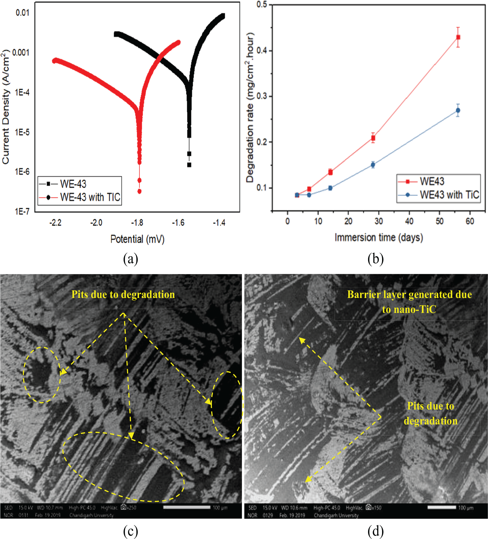
(a) Tafel curve, (b) degradation rate, ((c) and (d)) corroded morphology of WE43 composite in NaCl before and after nano-TiC reinforcement by friction stir processing.
Conclusion
In the current research work, the microstructure, mechanical properties, and corrosion resistance of the WE43/TiC composites processed through FSP has been studied, and the following conclusions have been drawn:
The grain size of the processed composites has drastically reduced and, therefore, enhanced the mechanical characteristics of the composites. It has been found that the grain size of the WE43 alloy has been significantly reduced from 22.42 to 6.6 µm after FSP process.
It has been noticed that the corrosion characteristics of the composite phase are severely influenced due to the introduction of TiC phase. The degradation rate of the processed WE43/TiC surface composite is found to be 45% higher than the unprocessed WE43 alloy.
The micrographic analysis indicated that the distribution and formation of clusters of the nano-TiC reinforcements in the WE-43 matrix was uniform with square tool-pin geometry.
However, in case of cylindrical and triangular tool-pin geometry repelled, the TiC reinforcements was found to be distributed in an entirely non-cluster and slightly-cluster manner, respectively.
It has been found that the tool-pin geometry has a strong influence of the micro-hardness and elastic modulus of the processed WE43/TiC composites. The square pin geometry has been found as the most effective to influence the formation of the composite phase and imparting required metallurgical changes.
Degradation rate of WE43/TiC composites was improved after reinforcement of nano-TiC by about 45% as compared to unprocessed WE43 alloy.
Footnotes
Acknowledgements
The authors would like to express their sincere gratitude to IKG Punjab Technical University, Jalandhar, India.
Declaration of conflicting interests
The author(s) declared no potential conflicts of interest with respect to the research, authorship, and/or publication of this article.
Funding
The author(s) disclosed receipt of the following financial support for the research, authorship, and/or publication of this article: This work has been supported by IKG Punjab Technical University, Jalandhar, India.