
Abstract
As one of the key technologies of high-temperature gas-cooled reactor, primary helium circulator–equipped active magnetic bearing provides driving force for primary helium cooling system. However, repetitive periodic vibration produced by rotor imbalance may introduce risks to primary helium circulator (even for high-temperature gas-cooled reactors). First, this article analyzes a periodic component extraction algorithm which is widely used in active magnetic bearing rotor unbalance control methods and points out the problem that the periodic component extraction algorithm occupies numerous computing resources which cannot satisfy the real-time request of active magnetic bearing control system. Then, a novel iterative learning control algorithm based on the iteration before last iteration of system information (iterative learning control-2) and a plug-in parallel control mechanism based on the existing control system are put forward, meanwhile, an integrated independent distributed active magnetic bearing control system is designed to solve the problem. Finally, both the simulation and experiment are carried out, respectively. The corresponding results show that the control method and control system proposed in this article have significant suppression effect on the repetitive periodic vibration of the active magnetic bearing system without degrading the real-time requirement and can provide important technical support for the safe and stable operation of the primary helium circulator in high-temperature gas-cooled reactor.
Keywords
Introduction
As a typical mechatronics system, active magnetic bearing(AMB) rotor system (AMBRS) of the primary helium circulator (PHC) provides technical conditions for the high clean helium circulation system in the primary loop of the high-temperature gas-cooled reactor (HTR). 1 However, the AMBRS has some problems such as mass imbalance, sensor runout, asymmetrical circuit, misalignment of geometric centers between the rotor and the stator,2–5 which would result in asymmetric magnetic forces produced by the AMB or the motor, and eventually lead to characteristic repetitive periodic rotor vibrations. Fortunately, the active control characteristics of AMB can provide favorable technical means for rotor vibration suppression of the PHC.6,7 However, the closed-loop feedback control system (CFCS), based on proportional–integral–derivative (PID) algorithm, cannot effectively control repetitive periodic vibration (RPV).
Until now, there are lots of research results on the AMB rotor unbalance control. From the literature research works,8–14 AMB rotor unbalance control methods were divided into unbalance compensation and automatic balance. The unbalance compensation is a method that can control the rotor spins around its geometric axis via compensating periodic signal, and the automatic balance is a method that can control the rotor spins around its inertia axis via ignoring periodic signal. The former is suitable for high-precision applications8,11 and the latter is suitable for high-speed applications.12,14
However, RPV is not only caused by the problems stated above, but also a large number of non-periodic disturbances existing in the operational process of AMB system. Therefore, most of unbalance control methods need to extract periodic components from the rotor displacement signal directly or indirectly. As mentioned in previous studies,11–15 the process of the periodic component extraction algorithm (PCEA) is basically divided into two steps: the first step is to calculate the coefficients of the frequencies to be extracted using the Fourier transform theory and the second step is to synthesize the periodic signals with respect to the frequencies using the inverse Fourier transform theory. This seems to be a very simple process but it takes numerous digital signal processing (DSP) computing resources in the AMB digital control system due to calling of the sine and cosine functions repeatedly. Obviously, this is a huge challenge to the real-time requirement of the control system. Therefore, if these algorithms are not processed in an efficient mode, PCEA based on Fourier transform theory is difficult to apply to the actual rotor unbalance control. Fortunately, iterative learning control (ILC) algorithm can deal with repetitive problems using the previous system information. 16 If ILC is applied to the AMB rotor unbalance control, then the control system may have sufficient time to complete the extraction of the rotor displacement periodic components through some ingenious mechanisms.
Actually, ILC has been widely and successfully applied in industrial fields with repetitive characteristics. Recently, lots of research works have been performed in the theory and application of ILC.17–21 From these research results, the structure of ILC algorithm is flexible, which provides convenience for selecting different previous system information according to different application needs.
In this article, the periodic vibration caused by the AMB rotor imbalance of the PHC is combined with ILC algorithm with the advantages in the aspect of repetitive periodic problems via using the previous system information. Iterative learning control-2 (ILC-2) is proposed for the AMB rotor unbalance control of the PHC. Furthermore, an integrated distributed parallel digital control system is designed for an AMB experiment system to verify the unbalance control method.
A novel ILC algorithm for the AMB rotor unbalance control
Problem formulation
Most research results on the AMB rotor unbalance control need to extract the periodic components of the signal, but unfortunately most of them only described the algorithm theory and did not analyze the existing problems from the perspective of digital control system.11–21 However, we found PCEA based on Fourier transform theory would occupy numerous computing resources, which ultimately cannot meet the real-time requirement of the control system.
Since the periodic vibrations of AMBRS have the same frequency or multi-frequency relationship with the period of rotor rotation (T). In other words, the frequencies of the periodic vibrations are integral multiples of the rotor rotational frequency. Certainly, the main component of the periodic vibrations is the synchronous vibration. Therefore, PCEA of displacement information is usually carried out based on T. Here, we assume that active magnetic bearing control system (AMBCS) can acquire N displacement signals within T, which is shown as

where
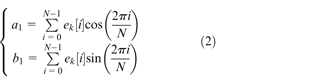


Unfortunately, the PCEA widely used in the AMB rotor unbalance control is performed at the end of the each rotation and cannot be performed in real-time. In addition, from the description of the algorithm as described in equations (2)–(5), a large number of sine and cosine functions need to be called in the process of solving the discrete Fourier transform. Although only a few low-frequency periodic components are needed to be extracted, this process would occupy numerous computing resources of DSP embedded system, 23 resulting in the failure to meet the real-time requirement of the control system. This is an important reason why many unbalance control algorithms cannot be effectively applied in the actual AMB system.
In the early stage of our research, the data loss rate of the control system was very serious, reaching about 20%, as the problem regarding PCEA that occupies numerous computing resources was not considered, which brought huge risks to the stable operation of the PHC. Therefore, how to solve the above problems is the key to the AMB rotor unbalance control.
Algorithm mechanism
ILC is a learning control method based on previous system information. It can effectively solve two problems in the AMB rotor unbalance control. One is that the learning mechanism can be used to suppress RPV disturbance produced by the rotor imbalance and the other one is that the control system can be given sufficient time to extract the periodic components using some ingenious mechanisms.
From the perspective of the ILC algorithm mechanism,16–24 the kth control input of the iterative learning controller can be described as
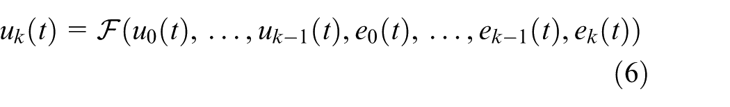
where
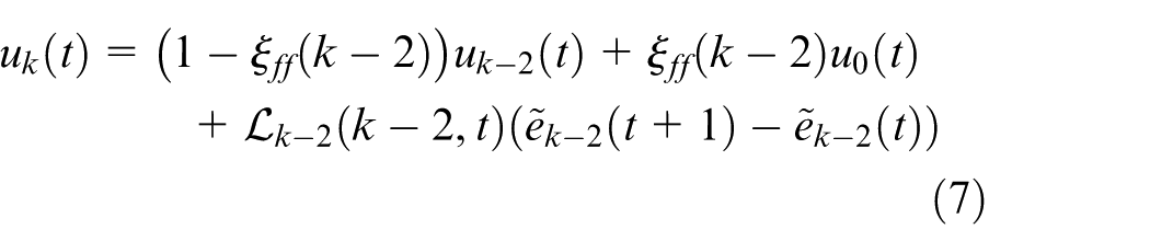
where
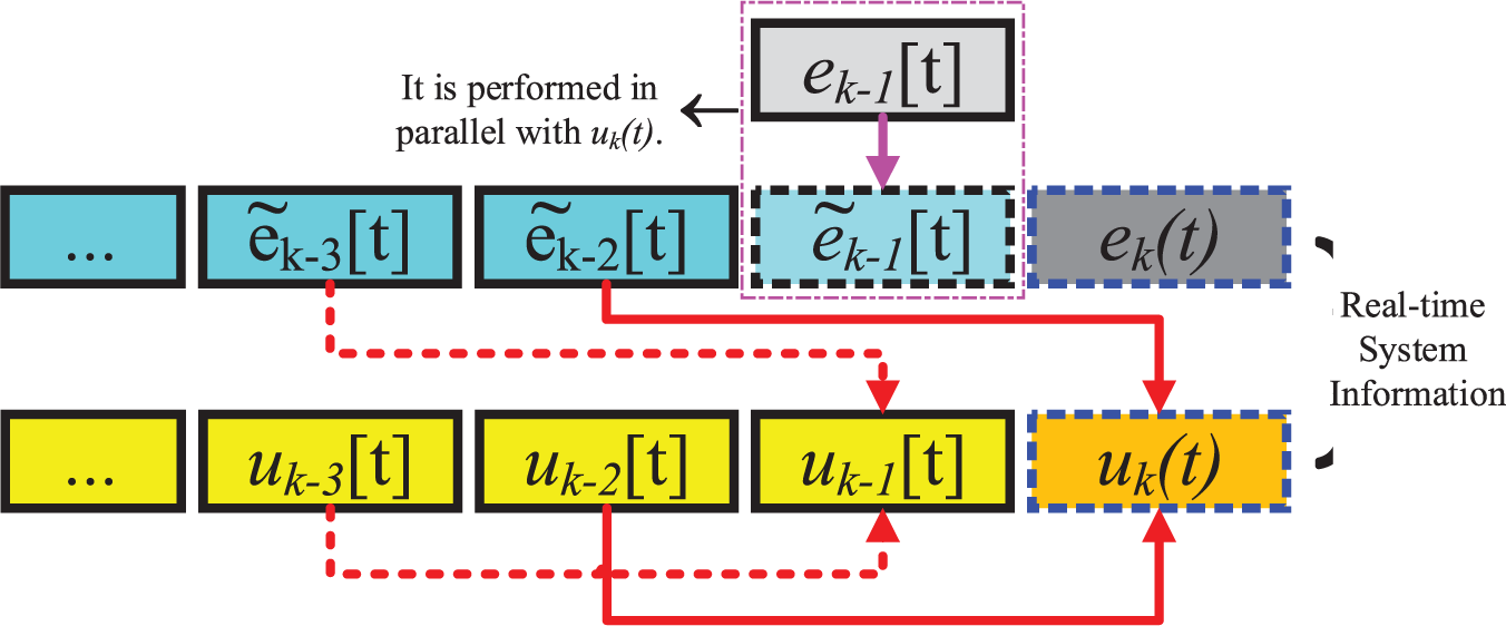
Mechanism diagram of ILC-2.
In Figure 1,
Algorithm analysis
Stability analysis
Here, the AMBRS with single degree of freedom (DOF) is taken as an example to analyze the convergence of the algorithm. The system model can be described as

where

Now, we need to assume that the system is reachable, that is, there exists a unique target control input sequence
The solution of the state equation of the discrete system is expressed in equation (8) and is described as 30
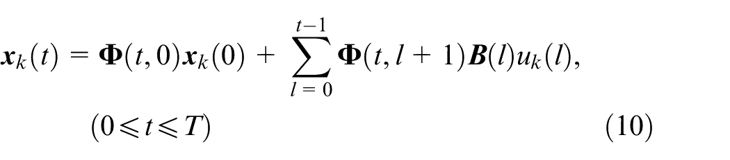
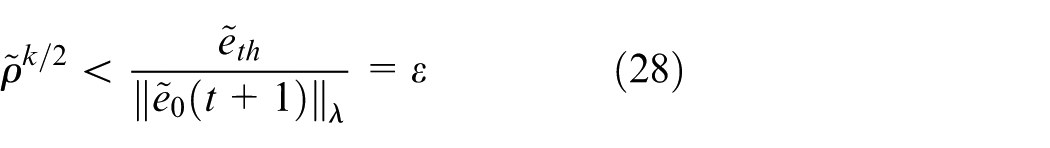
where
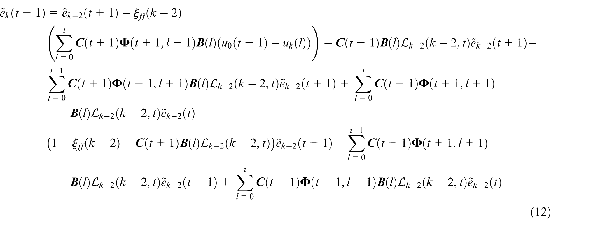
In this article, we analyze the convergence of the algorithm using the periodic component of the system control error. The analysis process is described as follows
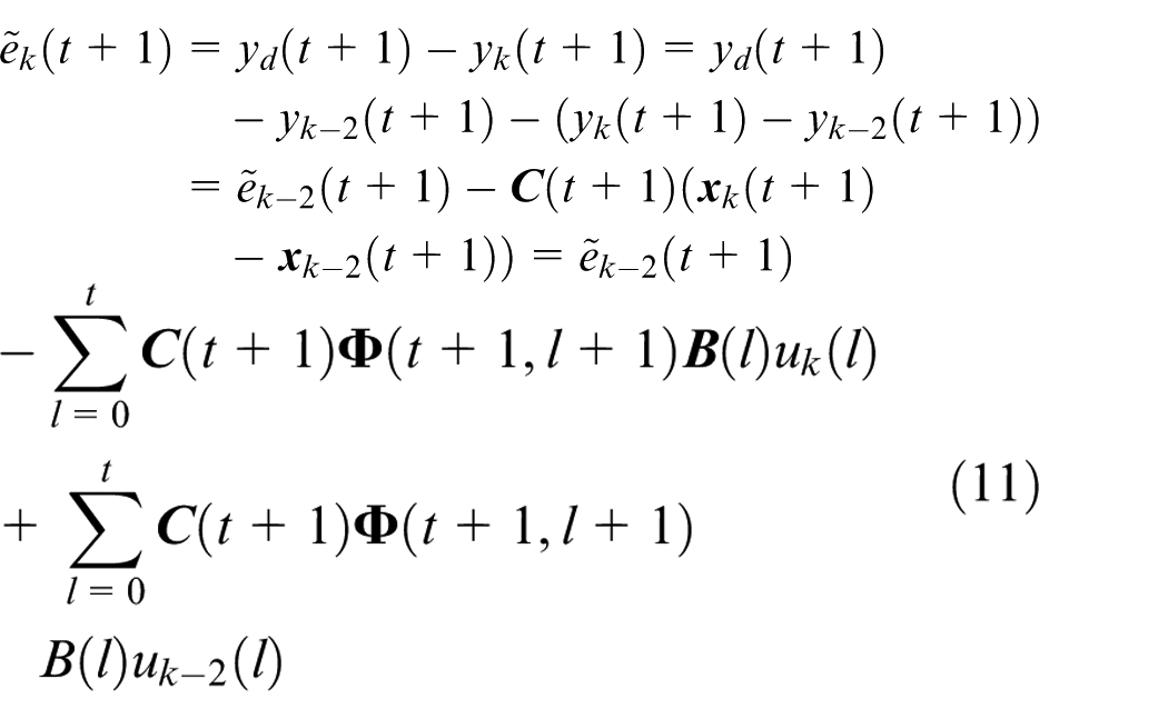
where
The norm of both sides of equation (12) satisfies the relation expressed in equation (13)
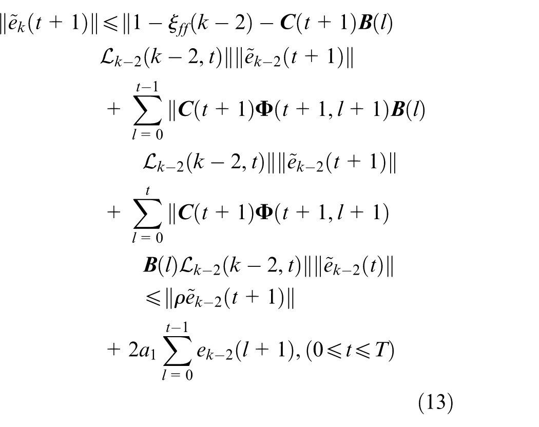
where we define
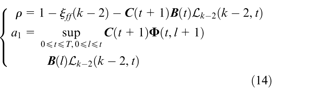
Multiplying both sides of equation (13) by
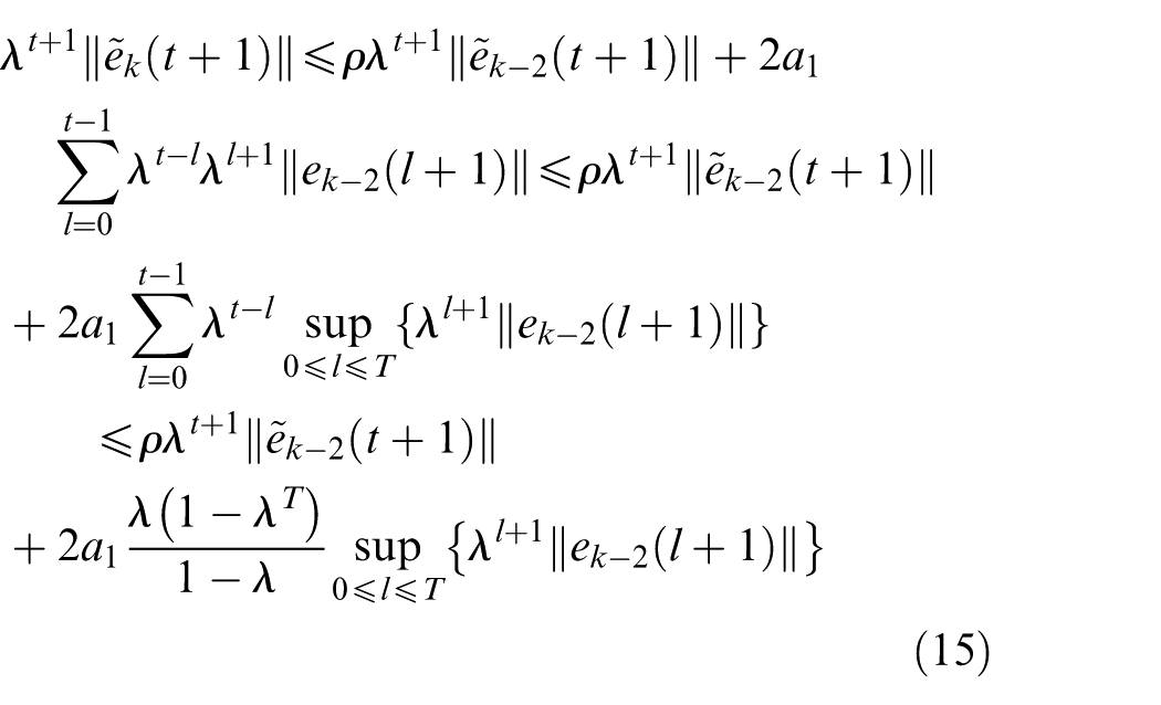
The supremum of equation (15) can be written as
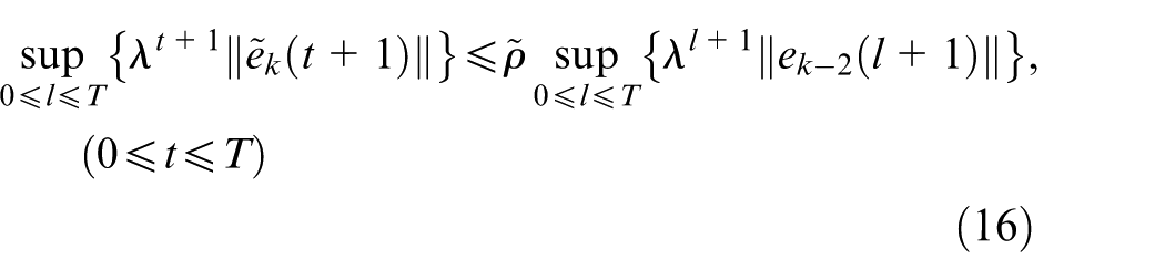
where

When the determined parameters are selected to meet
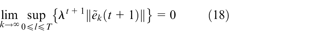
Since the process of ILC-2 is to successively search the target input sequence

To sum up, the convergence conditions for a single input single output (SISO) plant with the control algorithm expressed in equation (7), such as the AMB system with single DOF in PHC, can be summarized as follows

According to the above analysis process, consistent convergence conditions shown in equation (20) can be obtained as the ILC based on the last iteration of system information (ILC-1) with the same algorithm expressed in equation (7). And, our previous work has proved this conclusion.
Convergence rate analysis
From the above analysis, it can be known that the convergence conditions of ILC-1 and ILC-2 are consistent, but intuitively, the convergence speed of ILC-2 is slower than that of ILC-1. Obviously, a control algorithm with a very slow convergence rate has almost no application value in engineering. Therefore, the stability analysis is the essential requirement of the ILC algorithm, but the convergence rate analysis is also very important. Here, the spectral radius and iterations are introduced to evaluate the convergence rate of the ILC-1 and ILC-2 based on contracting mapping principle used in the above stability analysis.
Evaluation of convergence rate based on spectral radius
According to equation (16), the relationship of the system control errors based on ILC-2 of two successive iterations can be expressed as

Similarly, the relationships of the system control errors based on ILC-1 of two successive iterations can be expressed as


where

By comparing equations (21) and (24), it can be concluded that under the completely identical conditions that include the parameters and the initial state of the system, the convergence rate based on ILC-1 is faster than ILC-2.
2. Evaluation of convergence rate based on iterations
Practically, a threshold control strategy is generally adopted in the AMB rotor unbalance control, which means that the unbalance control is active only when the vibration amplitude exceeds a certain range. Therefore, it can be assumed that when the system has the same initial control error, which would converge within the threshold

Furthermore, according to equation (21), the following recurrence relations can be obtained (

Then, we get

where
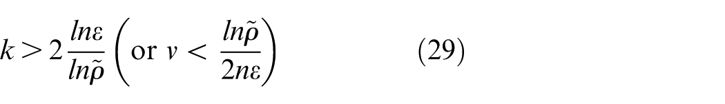
Similarly, the iterations or the convergence rate of ILC-1 needs to meet
From equations (29) and (30), we can get a conclusion that the evaluation of convergence rate based on iterations is consistent with spectral radius, which also fully conforms that the dependence of ILC algorithm on previous system information is gradually decreasing. Of course, this conclusion is also consistent with the ILC algorithm described in equation (7) and the convergence conditions described in equation (20).
Algorithm synthesis
To improve the convergence rate, ILC-2 expressed in equation (7) specifically adopts the setting methods with variable forgetting factor and variable learning gain. Here, we get


Here,
Furthermore, the variable forgetting factor and variable learning gain satisfy


This means that the system control input satisfy

The conclusion obtained above shows that the target control input sequence

ILC control system design for AMB rotor imbalance
AMB CFCS with single DOF
Although there exists a certain coupling in four radial DOFs of the mechanical rotor system, the AMBRS of the PHC is a typical rigid rotor with weak coupling. So, it can always be ignored in the actual control system design, which means that an independent distributed control strategy is adopted in four radial DOFs. Therefore, the AMB CFCS with single DOF is only needed to be discussed here, the block diagram is shown in Figure 2.
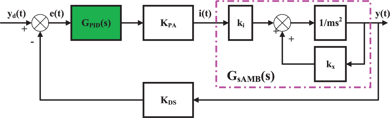
The block diagram of the AMB CFCS with single DOF.
In Figure 2,

Obviously, AMB is an unstable system, meanwhile, ILC-2 is an open loop control method that has no stabilizing effect on the system. Thus, the closed-loop feedback loop scheme must be used to achieve the system stability control. At present, PID control algorithms are always used in actual AMB system 6 and the PID control algorithm is described as follows
where

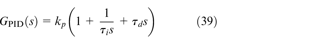
Parallel ILC mechanism based on CFCS
There are not only rotor imbalance, but also lots of reasons, such as circumstance noise, measurement error, which can produce vibration disturbances. To avoid the deterioration of ILC-2 performance by the non-periodic signals, it is also necessary to extract the periodic components according to equations (2)–(5). Therefore, a parallel ILC mechanism shown in Figure 3 is adopted to realize ILC-2 expressed in equation (7). Certainly, there are other combinations.31,32
The schematic diagram of a parallel control mechanism based on CFCS.
From Figure 3, the iterative learning controller (ILC-2) described in equations (7), (31), (32), and (33) for AMB rotor unbalance control is applied in parallel with PID controller. There are many advantages using this parallel control mechanism, such as the existing CFCS can be used to stabilize the AMB system and suppress the non-periodic vibration disturbances, which can make up for the deficiency of ILC-2. In addition, this parallel structure design does not need to change the original CFCS, which can reduce the cost of controller redesign and has practical engineering application significance in the optimization of AMB system.
Furthermore, the operating mechanism shown in Figure 3 can be described as:
First, the PID controller should continue to execute the PID algorithm in the time domain as before.
Second, the control system must calculate the control error
Third, when
In short, there are two reasons for the adoption of ILC-2. One reason is the real-time requirement of the ILC loop, which can avoid the problem of occupying the system computing resources due to the periodic component extraction. The other reason is that ILC-2 can ensure the convergence requirement with directly available system information
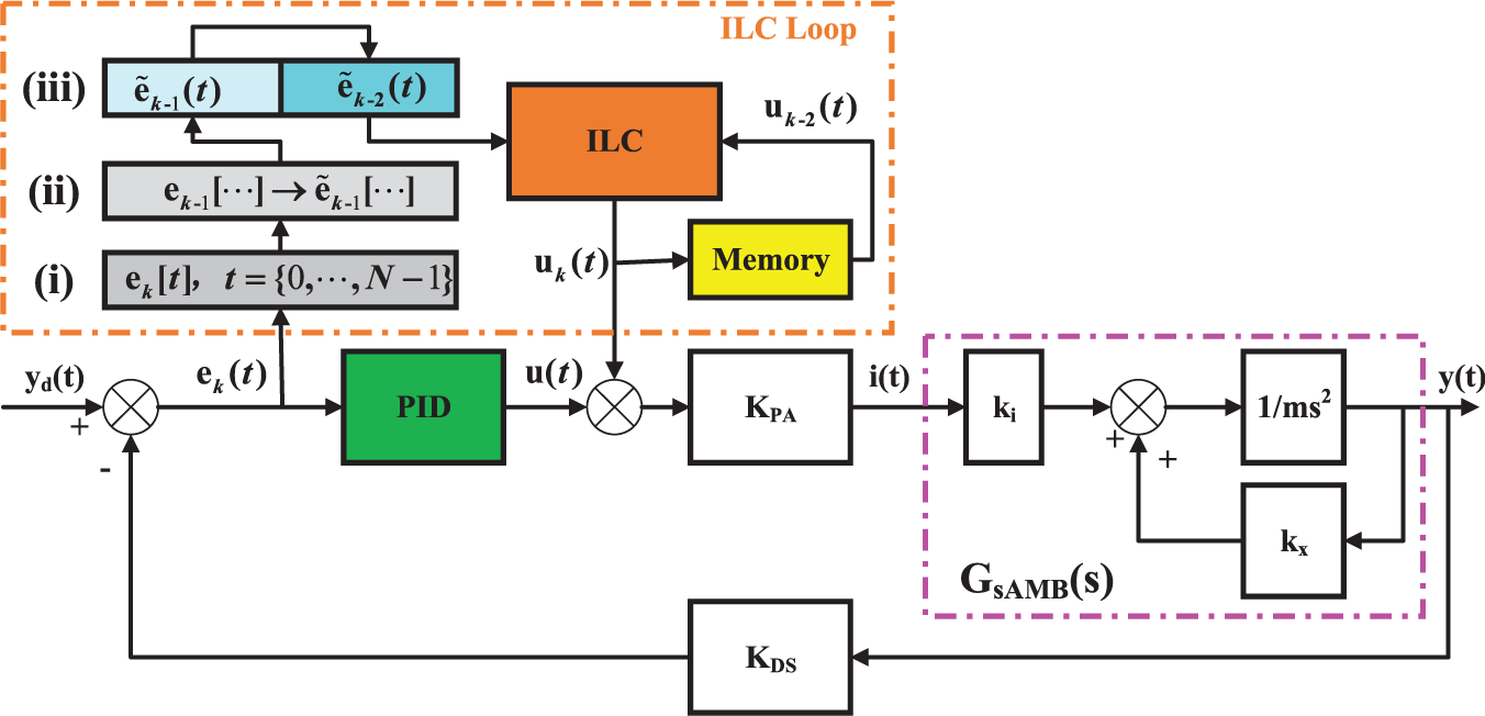
Rotor unbalance control system based on a parallel iterative learning mechanism
To keep consistent with the closed-loop feedback control strategy of the AMBRS in the PHC, this article adopts an integrated independent distributed parallel mechanism for four radial directions when designing the rotor unbalance control scheme. And the parallel control system is shown in Figure 4.
The integrated parallel control system for four radial directions in AMB of the PHC.
Therefore, it is necessary to upgrade the control system of the AMB test bench. The upgraded AMB test bench is shown in Figure 5, and is used to experimentally verify the control method proposed in this article.
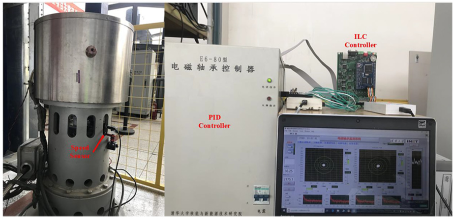
The upgraded AMB test bench.
The speed sensor in Figure 5 is used to detect the speed and phase of rotor rotation in real-time, and the real-time phase information is used to trigger each iteration. The AMB test bench adopts the self-developed digital control system, of which, ILC-2 controller and PID controller are all developed based on TMS320F28335. Meanwhile, control algorithms are developed on the Code Composer Studio 8.1.0 environment and flash_debug mode is adopted to observe parameters. In addition, NI USB 6215 with the frequency of 10 kHz is used to acquire the displacement signal of each control channel for real-time monitoring.
Experimental research on ILC method for rotor imbalance
In this article, experimental research works on the AMB rotor unbalance control method are divided into simulation and experiment. As the foundation of experiment research, simulation research can provide the basis for experiment directly. Therefore, this article adopts the real design parameters of the AMB test bench shown in Figure 5 to carry out the simulation research. Because the four radial directions are symmetric, this article just shows and analyzes simulation results for the AMB test bench with single DOF. The control parameters designed are shown in Table 1.
The control parameters designed for the AMB test bench with single DOF.
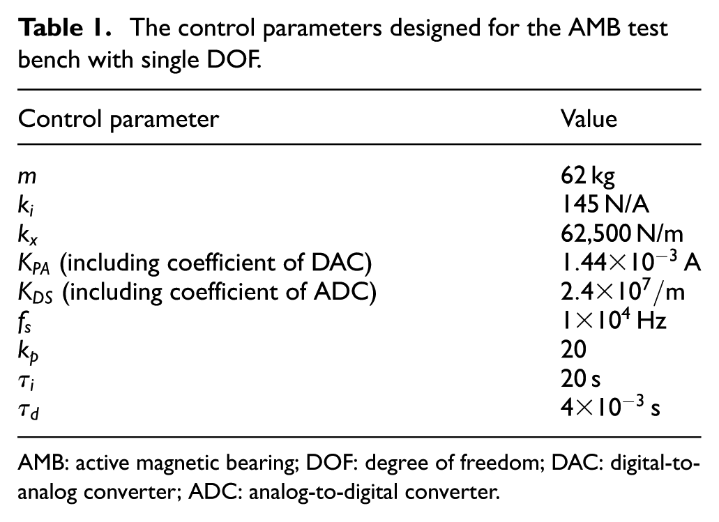
AMB: active magnetic bearing; DOF: degree of freedom; DAC: digital-to-analog converter; ADC: analog-to-digital converter.
The results of simulation
In the simulation, a sinusoidal signal and a random white noise signal are superimposed in the control loop, in which the sinusoidal signal is used to simulate the periodic vibration disturbance caused by the rotor imbalance, and the random white noise signal is used to simulate the random vibration disturbance. Then, three groups of simulation as shown in Table 2 are carried out for comparative analysis. The ILC parameters are set according to equations (31), (32), and (33), and
The groups of simulations.
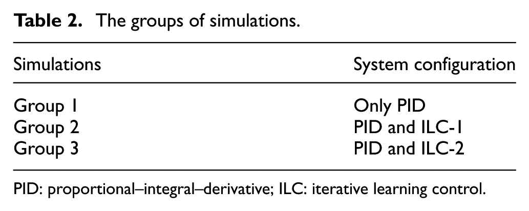
PID: proportional–integral–derivative; ILC: iterative learning control.
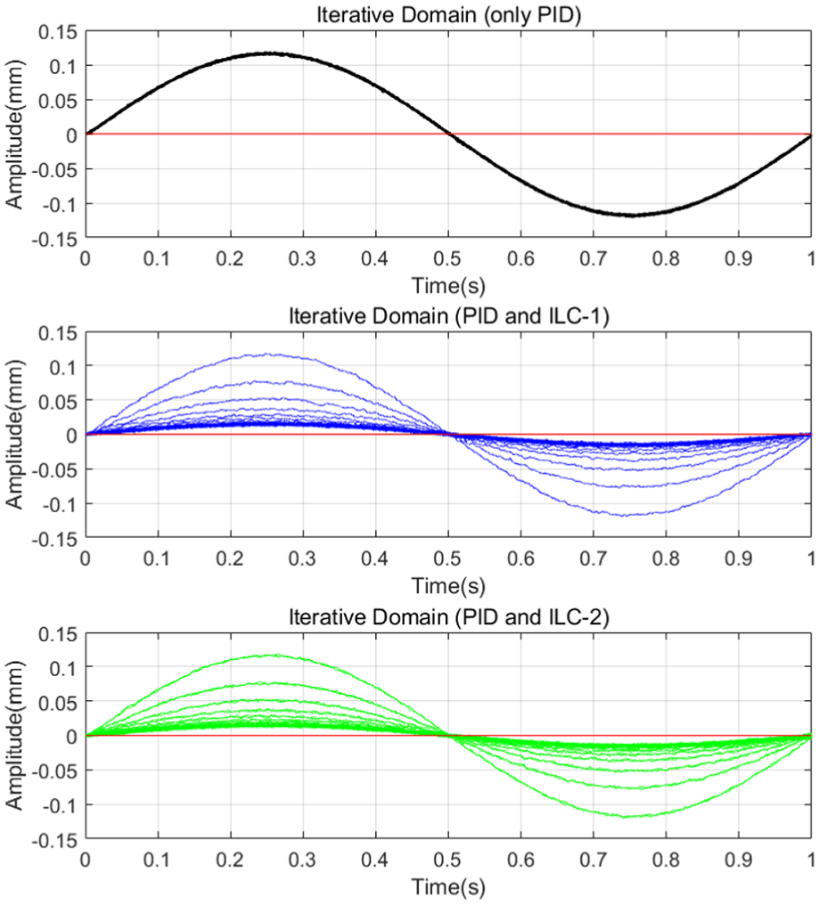
The curves of disturbances in iterative domain.
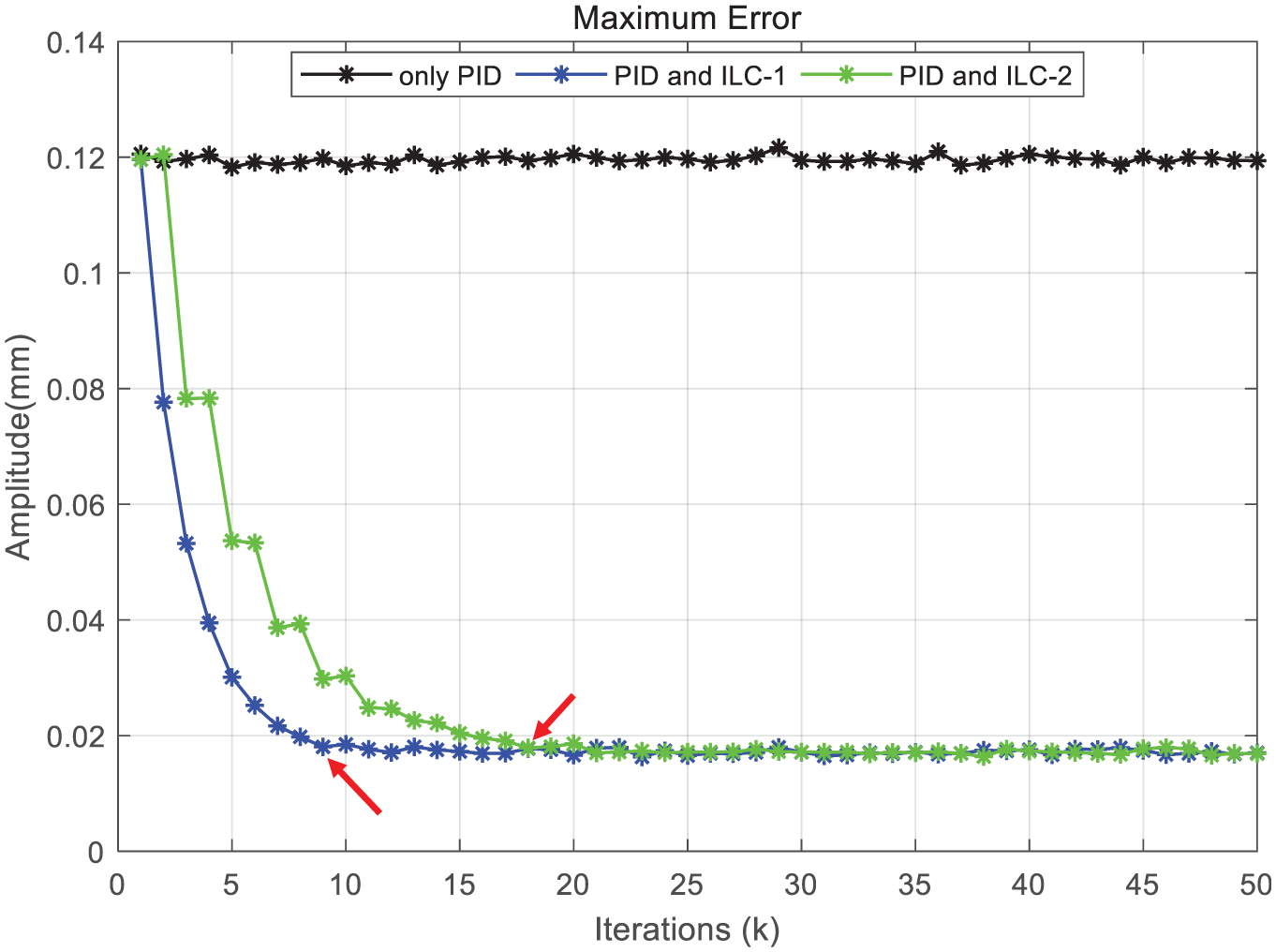
The maximum error curves of each iteration.
It can be seen from Figure 6 that the AMB CFCS based on PID alone cannot effectively suppress the repetitive periodic disturbance. This is because the PID algorithm is only based on the current system information and without learning from the previous system information, so it has little control effect on the repetitive periodic disturbance. Conversely, if the ILC loop is incorporated into the control system as shown in Figure 3, the repetitive periodic disturbance can be well suppressed, which indicates that ILC with the previous system information has a good control effect on repetitive disturbance. In addition, it can be further seen from Figure 7 that the control error converges to target value at the 9th iteration via ILC-1, while at the 18th iteration via ILC-2. Obviously, the relationship of iterations between ILC-1 and ILC-2 satisfies the theoretical calculation results of equations (29) and (30). Although the former is faster than the latter, the suppression effect of the two methods on repetitive periodic disturbance is consistent in the end.
The results of experiment
According to the results of simulation shown above, ILC-2 can satisfy the RPV of the AMB rotor. Although the convergence rate is slower, it is allowed in the AMB rotor unbalance control. Furthermore, the key is that ILC-2 can meet the real-time requirement of the control system, which is crucial to the system stable operation. To further verify the effectiveness of the control method proposed in this article, the experimental verification is carried out in the AMB test bench as shown in Figure 5. Considering that the PHC usually is operating at rated speed, thus the rotor unbalance control experimental researches are carried out at fixed speed at 4000 r/min
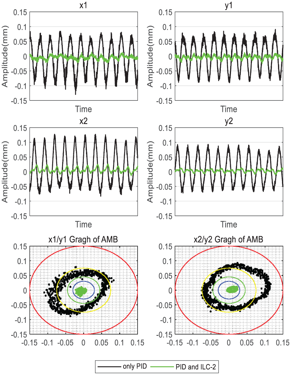
The comparison of disturbances in AMBRS between with and without ILC-2.
From the experimental results shown in Figure 8, The AMBRS have serious RPV disturbances in four radial directions only under the PID, which means that the PID controller has little control effect on the RPV disturbances. When the control method proposed in this article is adopted, the RPV disturbances are suppressed effectively, and the random disturbances are left finally which can conform to the feature that the ILC has no control effect on non-periodic disturbances. The axis loci shown in Figure 8 are circles or ellipses that indicates the rotor has obvious RPV disturbances. If the loci are too large, it may cause the collision between the rotor surface and the auxiliary bearing, which is not allowed in the AMB system. Therefore, the axis loci of the AMBRS need to be monitored in real-time when the PHC is operating. Certainly, the axis loci can be convergent to the safest range via ILC-2, which can provide basic guarantee for the safe and stable operation of the PHC in HTR.
Conclusion and discussion
Although ILC-2 proposed in this article is relatively slow in convergence rate, the results of the simulation and experiment show that it can effectively suppress the RPV disturbance produced by the AMB rotor imbalance. In addition, compared with ILC-1, ILC-2 can meet the real-time control requirement of the control system and provide a safety guarantee for the safe and stable operation of the AMB system. Meanwhile, compared with other unbalance control methods, ILC-2 does not need to detect the complex rotor imbalance as ILC can learn from previous system information. Obviously ILC-2 solves the problem that other AMB rotor unbalance control methods cannot meet the real-time requirement.
That is to say, the unbalance control problem of the AMB rotor imbalance in PHC is solved through the novel learning mechanism proposed in this article. Furthermore, the research results of this article can provide the theoretical and experimental basis for the safety and stability of the PHC and the HTR. Of course, it can be further extended to the other AMB application fields.
Footnotes
Declaration of conflicting interests
The author(s) declared no potential conflicts of interest with respect to the research, authorship, and/or publication of this article.
Funding
The author(s) disclosed receipt of the following financial support for the research, authorship, and/or publication of this article: This work is supported by National Science and Technology Major Project (No. 2019ZX06903019) of China.